Vivotek SC8131 User Manual
Stereo network camera
Hide thumbs
Also See for SC8131:
- Quick installation manual (4 pages) ,
- User manual (38 pages) ,
- Manual (63 pages)
Table of Contents
Advertisement
SC8131
User's Manual
1MP • Stereo Camera • 3D Tracking • People Counting
Stereo
Network Camera
Rev. 1.8
Advertisement
Table of Contents

Related Manuals for Vivotek SC8131


Summary of Contents for Vivotek SC8131
- Page 1 SC8131 Stereo Network Camera User’s Manual 1MP • Stereo Camera • 3D Tracking • People Counting Rev. 1.8...
- Page 2 Ready to Use ................................ 44 Accessing the Network Camera ........................... Using Web Browsers ............................45 Using RTSP Players ............................. 48 Using 3GPP-compatible Mobile Devices ......................49 Using VIVOTEK Recording Software ........................50 Stereo Tracker ............................... 1. Live View................................2. Report .................................
- Page 3 Security > Access List ..........................186 Applications > DI and DO ......................... 191 Package management ..........................192 (VADP, VIVOTEK Application Development Platform) ................192 Online Registration ........................... 194 Stereo Tracker - the Embedded VADP Module ..................196 Recording > Recording settings ......................197 Local storage >...
- Page 4 VIVOTEK Overview The VIVOTEK SC8131 is a stereo camera that provides precise tracking and people counting functionality. The dual-lens stereo camera design eliminates the defects of single-lens cameras in video analysis applications. Unlike single-lens applications that are easily affected by lighting changes or shadows, this camera enables stereo visions that accurately tracks the 3D positions of objects moving across the field of view.
- Page 5 ■ Rev. 1.5: • Corrected DI/DO pin related description. ■ Rev. 1.6: • Added the installation height FOV tables for SC8131-F2, -F4, and -F6. ■ Rev. 1.7: • Added description for Queue Analysis and service time counting. See page 79. •...
- Page 6 Network Camera and ensure proper operations. For creative and professional developers, the URL Commands of the Network Camera section serves as a helpful reference to customizing existing homepages or integrating with the current web server. Package Contents ■ SC8131 ■ Mounting plate ■ Screw pack ■ Software CD ■...
- Page 7 VIVOTEK Symbols and Statements in this Document INFORMATION: provides important messages or advices that might help prevent inconvenient or problem situations. NOTE: Notices provide guidance or advices that are related to the functional integrity of the machine. Tips: Tips are useful information that helps enhance or facilitate an installation, function, or process.
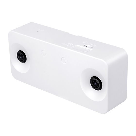
- Page 8 VIVOTEK Physical Description Front Panel LEDs Dual lenses Rear Panel Mounting hole DI/DO terminal block RJ45 port Retainer rivets 8 - User's Manual...
- Page 9 VIVOTEK Top View Release tab MicroSD card slot Reset USB for iBeacon The USB port output is 5V, 2.42W WARNING: Please do not remove the protective sheet before the installation is done. Dirty lens can seriously affect the accuracy of video analysis.
- Page 10 VIVOTEK Installation Heights SC8131(F2): 240~500 cm (7.9~16.4') SC8131(F4): 500~800 cm (16.4~26.2') SC8131(F6): 800~1000 cm (26.2~32.8') SC8131-F2 Zoom ratio FOV (Horizontal) HFOV HFOV HFOV HFOV HFOV HFOV HFOV HFOV HFOV Distance with next camera Height (H)* 140.1 254.8 242.1 229.4 216.6 203.9...
- Page 11 VIVOTEK SC8131-F4 Zoom ratio FOV (Horizontal / Vertical) HFOV VFOV HFOV VFOV HFOV VFOV HFOV VFOV HFOV VFOV Distance with next camera Height (H)* 225.0 274.9 177.8 261.2 168.9 247.4 160.0 233.7 151.1 220.0 142.2 249.9 299.9 193.9 284.9 184.2 269.9...
- Page 12 VIVOTEK SC8131-F6 Zoom ratio FOV (Horizontal / Vertical) HFOV VFOV HFOV VFOV HFOV VFOV HFOV VFOV HFOV VFOV Distance with next camera Height (H)* 147.6 295.3 209.9 280.5 199.4 265.8 188.9 251.0 178.4 236.2 167.9 164.1 311.7 221.5 296.1 210.4 280.5...
- Page 13 VIVOTEK Considerations Note the following when planning the camera installation: 1. The installation site must be adequately lighted for optimal accuracy with video analysis. 2. It is preferred that the camera is mounted directly above the objects to be counted. Use tools such as a spirit level to ensure the camera is installed level.
- Page 14 VIVOTEK 3. By building a 3D depth map from an overhanging position, the objects' height information can be acquired, and thus the drawbacks of 2D video counting can be eliminated. The silhouette of heads and shoulders and their relative depth information enable the camera to distinguish human activities from the background and other objects, such as shadows, shopping carts, and dogs.
- Page 15 VIVOTEK 5. Below are the configuration elements for operating the SC8131 3D camera: . Found physical characteristics of humans & starts tracking... Start point Detection line Detection area Object tracking line [45] H=181 Detected object Tracking end point The counting takes place when a moving object appears in the detection area and moves across the detection line.
- Page 16 VIVOTEK 6. For counting to work properly, you should avoid having the view covering a large portion of walls as shown below. 6-1. Keep camera away from wall or other obstacles to optimize the effectiveness of FOV. 6-2. Select a location that can cover a longer object trajectories for better tracking results.
- Page 17 VIVOTEK 8. An effective counting requires an object to be detected, and then moves across the detection line. Avoid setting the line too close to the edge of detection area. Not enough space to recognize objects..Detection line Detection area 9.
- Page 18 VIVOTEK 10. Always configure the coverage of the detection area in that the complete silhouette of objects can be contained. If only part of the moving object is covered, the counting will fail. The entire object needs to appear in the detection area for the camera to acquire its height information.
- Page 19 VIVOTEK Detection line Start point Object tracking line Detection area End point 12. If the camera needs to be installed unavoidably at a position higher than 3.6 meters, you can use the Zoom-in mode configuration. See the Stereo Tracker > Configuration page.
- Page 20 VIVOTEK 13. For Line Crossing and countng configuration, unnecessary objects should be avoided. A door, a floating curtain, and moving objects such as an escalator can cause mistakes with calculation. 14. If the VAST software is used for accumulating counting results, set the counting event notification option to the "real-time"...
- Page 21 VIVOTEK Patterned surface - Some other possible sources of interference may include: shadows on the wall, mirrored object image on the reflective surface. Check if the region exclusive setting should be applied when the Depth view video shows flickering white noises in some regions, or, object trajectories are likely to be trapped within these regions.
- Page 22 VIVOTEK Stitching Considerations The following applies when stitching multiple SC8131 cameras: 1. The Stitching configuration takes place on the Master camera. 1 Master camera with up to 6 Slave cameras can form a stitiching configuration. 2. All Master and Slave cameras in a Stitching configuration should be running the same firmware.
- Page 23 VIVOTEK 7. Once the Stitching configuration is done, the positioning order of peer cameras will be fixed, and you cannot change their Stitching order unless you unstitch them. Consider the following when stitching multiple cameras to form a large virtual floor plan: Height (cm)* Dist.
- Page 24 VIVOTEK Tilt Considerations 1. The camera should be mounted in a downward looking orientation. The tilt and yaw should be level so that it is looking straight down. In some cases, the camera may need to be installed to count the people passing the front of a store's entrance.
- Page 25 VIVOTEK Queue Analysis Considerations Design Purpose: Provides a count of people waiting in line and the duration of time of their wait, or the time being serviced. The collected count data can be used by managers to improve staff management, service, and store layout.
- Page 26 VIVOTEK There are counters that have different service positions and wait positions, such as the immigration check counters at the airports. As long as the camera's FOV can cover, you can draw different Service zones and Queue direction boxes at appropriate positions.
- Page 27 VIVOTEK Passer-by Counting Considerations Design Purpose: Provides a count of people who pass by near an entrance but without entering. The count can be used to evaluate how many people may have shown their interest but lack the motive to enter a store.
- Page 28 VIVOTEK A man walked through the passer-by area but through the flowpath: 1 passer-by count. 1 passer-by count Flowpath Passer-by area Extend to cover the around- The Passer-by Counting takes effect in both single camera or stitched cameras the-corner traffic configurations.
- Page 29 VIVOTEK General I/O Terminal Block This Network Camera provides a general I/O terminal block which is used to connect external input / output devices. The pin definitions are described below. The maximum DO+ 12V output load is 0.5A. DI/DO Diagram 1.
- Page 30 VIVOTEK Wet contact with external DC power source to supply a relay. Switch DC 0V External DC power External AC power with Protected Earth Relay External Device Dry contact and using camera’s DO+ to supply a relay. Switch External AC power...
- Page 31 VIVOTEK Hardware Reset Recessed Reset Button The reset button is used to reset the system or restore the factory default settings. Sometimes resetting the system can return the camera to normal operation. If the system problems remain after reset, restore the factory settings and install again.
- Page 32 VIVOTEK Install the Camera 1. Jot down the camera's MAC address for later reference. SC8131 0002D10766AD 2. Plan the installation features, e.g., position and installation height. Recommended Installation Height • Installation Height: 2.4M ~ 3.6M • Coverage area: 1.7M ~ 5.1M...
- Page 33 VIVOTEK Installation Option A: Using the Mounting Plate A1. Attach the alignment sticker to a preferred position. If preferred, drill a cabling hole. See below for the diameters of it. Ø15 RJ45 Ø15mm A2. Route an Ethernet cable through the cabling hole.
- Page 34 VIVOTEK A3. Drill mounting holes and hammer the included anchors into the mounting holes. Ø15 RJ45 A4. Secure the mounting plate to ceiling using the included screws. Ø15 RJ45 34 - User's Manual...
- Page 35 VIVOTEK A5. Connect the Ethernet cable to the camera. Ø15 RJ45 RJ45 A6. Align the camera with the bracket, and slide the camera to the right. The camera will then be securely mounted to the bracket. Note that the side with two LEDs is the top side, and should be aligned with the arrow mark on the mounting plate.
- Page 36 VIVOTEK To remove a camera, use a flat blade screwdriver. Press it down against the release tab from the top side and slide the camera to the left. 36 - User's Manual...
- Page 37 VIVOTEK Installation Option B: Using the Camera Stand The camera can also be mounted to standard camera stands, such as VIVOTEK's AM-131. User's Manual - 37...
- Page 38 VIVOTEK Installation Option C: Mounting to the Single Gang Box C1. You can also install the mounting bracket to a 4"x2" single gang box. C2. When installing the bracket, press the bracket toward the center of the box so that the bracket can rest firmly on the surface of the box.
- Page 39 VIVOTEK When the installation is done, remove the protective sheet. Use the Shepherd utility to find and access the camera. Open a web console with the camera. PoE switch Shepherd Browser The default user name and password is root / root.
- Page 40 VIVOTEK You can use the shortcut on the home page or open the Configuration > Application > Package management page to access the tracking and counting configuration utility. Please refer to page 51 for the configuration details about the embedded Stereo Tracking and Counting functionality.
- Page 41 VIVOTEK Internet connection via a router Before setting up the Network Camera over the Internet, make sure you have a router and follow the steps below. 1. Connect your Network Camera behind a router, the Internet environment is illustrated below.
- Page 42 For more information with network configuration options (such as that of streaming ports), please refer to Configuration > Network Settings. VIVOTEK also provides the automatic port forwarding feature as an NAT traversal function with the precondition that your router must support the UPnP port forwarding feature.
- Page 43 Software Installation 1. Install the Shepherd utility, which helps you locate and configure your Network Camera in the local network. If your camera comes without the CD, go to VIVOTEK’s website, and locate the utility in the Downloads > Software page.
- Page 44 VIVOTEK Ready to Use 1. A browser session with the Network Camera should prompt as shown below. 2. You should be able to see live video from your camera. You may also install the 32-channel recording software from the software CD in a deployment consisting of multiple cameras. For its installation details, please refer to its related documents.
- Page 45 3. The live video will be displayed in your web browser. 4. If it is the first time installing the VIVOTEK network camera, an information bar will prompt as shown below. Follow the instructions to install the required plug-in on your computer.
- Page 46 VIVOTEK ► By default, the Network Camera is not password-protected. To prevent unauthorized access, it is highly recommended to set a password for the Network Camera. For more information about how to enable password protection, please refer to Security on page 178.
- Page 47 Multiple web sessions can stress the camera. 2. If you are operating the latest VIVOTEK Rossini series cameras, the Java plug-ins that came with them may cause compatibility issues on the browser. Try remove the plug- ins.
- Page 48 VIVOTEK Using RTSP Players To view the video streaming media using RTSP players, you can use one of the following players that support RTSP streaming. Quick Time Player VLC media player VLC media player 1. Launch the RTSP player. mpegable Player 2.
- Page 49 VIVOTEK Using 3GPP-compatible Mobile Devices To view the streaming media through 3GPP-compatible mobile devices, make sure the Network Camera can be accessed over the Internet. For more information on how to set up the Network Camera over the Internet, please refer to Setup the Network Camera over the Internet on page To utilize this feature, please check the following settings on your Network Camera: 1.
- Page 50 Network Camera to the Channel list. For detailed information about how to use the recording software, please refer to the user’s manual of the software or download it from http://www.vivotek.com. 50 - User's Manual...
- Page 51 VIVOTEK Stereo Tracker NOTE: • For the design and configuration rules, please refer to page 13. • For a management session across a firewall or router (over the Internet), it is necessary to open a Websocket port 888 (or secure port 889) on your router using the NAT traversal method for transferring metadata for counting.
- Page 52 VIVOTEK • Display elements: Click on the display button at the lower right to select the count indicators. 1. Show exclusive area: displays the exclusive areas, if configured. 2. Show start stop map: displays the start and stop points of moving objects captured by the camera.
- Page 53 VIVOTEK Tips If you encounter the display problems with the Stereo Tracking window, try the following: 1. Try clear the browsing history. Sometimes, plug-ins from the previous browser sessions may still affect the current session. 2. Press the F12 key when you open the IE10/IE11 console window. Make sure you are not running the browser in the Compatibility mode.
- Page 54 VIVOTEK 2. Report The Report page displays an instant graph showing the activivities in a day's span. You can also export the collected data using the Export data pane below. Select the time span, UTC time (Coordinated Universal Time), file format, and interval. Note that polling the data from camera may take several minutes.
- Page 55 VIVOTEK The report page also supports the display of the Queue Analysis results. Select a pre- configured Queue Analysis rule. Select a day or spans of days. The accummulated results can be displayed in a chart. You can single-click to disable a display element. For example, you can choose to display the Average waiting duration.
- Page 56 VIVOTEK Export Data The Export data window allows you to manually export all analytics results. Up to 2,000 entries will be stored on the camera. Users can export the report using the XML, CSV, or JSON format with the granularity of 1, 5, 15, 30 minutes, or 1, 12, 24 hours.
- Page 57 VIVOTEK 3. Configurations To start configuring the tracking and counting rules, click on Configurations. The Camera settings window will appear. 3-1. Configuration - Camera settings The Camera settings page contains key parameters related to the physical characteristcs at your installation site. You need to carefully tune the parameters to acquire the best detection results.
- Page 58 VIVOTEK • Calibrate: Users can calibrate the installation height especially when installing the camera for the first time. The calibration function helps verify the correctness of the dual-lens depth map in the stereo vision. The correctness of such vision can be affected by incorrect intallation.
- Page 59 VIVOTEK • Depth noise filter level: An analytics mechanism filters out unreliable depth correlation data in cases where homogeneous surface or periodic pattern scene exist. Chances are it may be impossible to ignore these regions because objects may still pass through these regions.
- Page 60 VIVOTEK This is the view of the installation site. The white wall is unavoidable. Homogeneous and unavoidable area Shown below is the result when the Depth noise filter level is tuned up. White noises have disappeared. 60 - User's Manual...
- Page 61 VIVOTEK • When to consider decreasing Depth noise filter level? If camera installation height is higher, the effective area of a person moving in the depth map will be smaller. If camera installation is higher than 3.3 meters, it is recommended to revise the following settings to minimize the possibility of losing objects' tracks.
- Page 62 VIVOTEK • Stream type: The following display options are available: * Single Eye Rectified HD video (up to 1280x960) * Depth view video (320x208) See the Configuration > Camera Settings page. • Show Detect Area: Select to display the effective detection area currently enabled by your analytics rules.
- Page 63 VIVOTEK 3-2. Configuration - Stitch camera Video Stitching can be used to bring up to 7 SC8131s together to provide video analytics over a large and wide floor plan. Count lines can then be be applied individually or across the FOVs of multiple cameras to cover a wide area.
- Page 64 VIVOTEK 2. Enter the IP addresses of the cameras that will serve as the Slave cameras. Enter the credentials if they all use the same credentials. It is recommended that you configure a static IP for all Master and Slave cameras.
- Page 65 VIVOTEK 4. Before you click the Stitch button, make sure you have a co-worker to walk across the overlapped FOV between the cameras that will be stitched together. Note that he/she should walk across the overlapped FOVs by entering, leaving, and repeating the process for about 2 minutes.
- Page 66 VIVOTEK Stitching proceeds as a consecutive process. It can proceed wtih one Master and multiple slave cameras, and proceeds until all Slave camera are stitched. Master Slave #1 Slave #2 Slave #3 ..There is no time limits on the Stitching process. Starting from the first Slave camera,...
- Page 67 VIVOTEK The process can be stopped and reversed at any stage if any errors should occur. When Stitching is completed, the stitched, elongated image will be available on the live view. Proceed with configuring the analytics rules and other configurations.
- Page 68 VIVOTEK 3-3. Configuration - Analytics rules Click on Configurations > Analytics rules to open the Analytics configuration window. Click on the Add button to create a new rule. 3-3-1. Analytics rules - Counting (1st type) A Configuration window will prompt. Click on the Add new rule button to start the configuration.
- Page 69 VIVOTEK Note that there are 4 Analytics types: 1. Counting, 2. Zone detection, 3. Flowpath, 4. Queue Analysis. The configurable parameters are different for these 4 types. • Direction: Select Counting paramters as In, Out, or In & Out. If not selected, e.g., selecting the In count only, only the In counts will be recorded and reported.
- Page 70 VIVOTEK Analytics rules - Zone detection (2nd type) Zone counting: Records the time and quantity as people enter, leave, and waiting in the zone. Applications: To analyze how many people enter a certain area of a store. To communicate how many people frequent a retail counter.
- Page 71 VIVOTEK The statistics in zone detection reports are described as follows: Report tag name Description Inward count Number of objects which went inward in aggregation time. Sum Outward duration Sum of dwell time for objects that left the zone before the end of aggregation time.
- Page 72 VIVOTEK Analytics rules - Flow Path Counting (3rd type) • Counting rules: The Counting rule configuration enhances count accuracy with configurable preferences if people linger or make U turns in the FOV. One presumption is that a moving object must stay within the FOV during its movement for the Counting modes to take effect.
- Page 73 VIVOTEK 1. Objects Entering from the "In" side: Count Include U turn Exclude U turn from outside (After exit) (First pass) Count Include U turn Exclude U turn from outside (After exit) (First pass) 2. Objects Entering from the "Out" side:...
- Page 74 VIVOTEK The "Include U turn from the the out side" mode applies when in a crowded, confined area, such as the area near the a bus door. People may gather near the door without leaving the FOV, while it is still necessary to count the number of people moving In or Out of the vehicle.
- Page 75 VIVOTEK During the transition stage (from close to open), objects in a specific area will be considered as already been counted as the "In" count. When they leave the area, they will be counted as "Out." Sensitivity of the area near the vehicle door will be raised, since the traveling distance for people who have been there may be short.
- Page 76 VIVOTEK 3-3-2. Analytics Rules - How to Draw a Flowpath Flow path is another detection rule type. When passengers pass along the flow path, the camera will record the event and immediately update the counting report on the Liveview page.
- Page 77 VIVOTEK Because the counting rule of Flow path is based on the entering point and the leaving point of one tracked object and the shape of the flow path scheme, it is important to configure the flow path rule carefully depending on the monitored scene. The following are the...
- Page 78 VIVOTEK 3-3-3. Passer-by Counting (4th type) The configuration of Passer-by Counting is similar to the flowpath configuration as previously described. An additional Passer-by Area is configurable if this counting mode is selected. To configure the Passer-by counting: 1. Enter a comprehensive name for the configuration, such as Queue_detect1.
- Page 79 VIVOTEK 3-3-4. Queue Analysis (5th type) Queue Analysis rovides a count of people waiting in line and the duration of time of their wait. To configure the Queue Analysis: 1. Enter a comprehensive name for the configuration, such as Queue_detect1.
- Page 80 VIVOTEK The configuration criteria are listed below: 1. The Service zone should be used to cover the area right in front of the counter. The zone should cover the maneuver of one person. 2. The Queue direction box should have its arrow marks pointing the service provider.
- Page 81 VIVOTEK Queue analysis delay: Start analysis after seconds: This threshold applies when 1 person is already standing in the Service zone, and the other enters the Queue area. Stop analysis after seconds: The threshold applies when one leaves the Queue or Service zone.
- Page 82 VIVOTEK Note that if no one stands in the Service zone, the Length (People) count will not start even when there are people standing in the Queue box area. This situation may indicate that there is no service provider sitting behind the counter.
- Page 83 VIVOTEK 3-4. Event Rules With the counting rules set up, you can configure a specific rule to be delivering a triggering condition to a receiver. For example, an event can be delivered when the number of counts exceeds a preset number. You will then know the status, say, when the number of remaining people in a building is larger than a preset number.
- Page 84 VIVOTEK One example is to configure a zone alarm event if a specific area is populated by more than one people, such as an area in front of an ATM. You can also select the Maximum, the Minimum, and the Average waiting duration for applications such as improving the efficiency of the checkout area.
- Page 85 VIVOTEK 3-6. Report Push Configure the report push protocols so that you can receive periodic counting reports. The reports include camera information and aggregated counts by the configured intervals for each counting rule. Click the Add button to begin. Status...
- Page 86 VIVOTEK Localtime Presents the input starttime, endtime, and the StartTime, EndTime in a report as camera local time. If not selected the input starttime, endtime and all time format in report is in UTC (Universal Time Coordinated) timestamp. Include When selected, the report will include a "status" column.
- Page 87 VIVOTEK Server type: Fill in the event report agent information: Email Sender email A valid sender email Recipient email A valid receiipient email Server address SMTP server IP address User name User name for SMTP server authentication credentials Password Password for SMTP server authentication credentials...
- Page 88 VIVOTEK * Listed below are the variables for the customized file name. Report timestamp in UTC time Report formal in xml, json, or csv User defined server name Year in 4 digits Month of the year in 2 digits Day of the month in 2 digits...
- Page 89 VIVOTEK The camera will post an XML file to server, the description of XML (XSD) is as below: <?xml version="1.0" encoding="UTF-8"?> <xs:schema xmlns:xs="http://www.w3.org/2001/XMLSchema" elementFormDefault="qualified" attributeForm Default="unqualified"> <xs:element name="Message"> <xs:complexType> <xs:sequence> <xs:element name="Source"> <xs:complexType> <xs:sequence> <xs:element name="UtcTime" type="xs:string"></xs:element> <xs:element name="GroupID" type="xs:string"></xs:element>...
- Page 90 Counting,Counting2,0,0,2015-05-28T06:15:00Z,2015-05-28T06:30:00Z Below is the JSON example showing the same condition in json format. a zero counting data will still be sent if you deselect the lite mode. "Source": "UtcTime":"2015-05-28T06:30:01Z", "GroupID":"0", "DeviceID":"0", "ModelName":" SC8131", "MacAddress":"00:02:81:31:00:08", "IPAddress":"172.16.2.134", "TimeZone":"+8", "DST":"0" "Data": "RuleType":"Counting", "CountingInfo": "RuleName":"Conting1",...
- Page 91 VIVOTEK In addition to these, if you want to acquire the report directly from CGI, use the following command to receive the report in different formats: http://{IP}/cgi-bin/admin/scevent_pull.cgi? format={xml,json,csv}& starttime={starttime timestamp} & endtime={endtime timestamp} & aggregation={aggregation level in seconds} & lite={0,1}&...
- Page 92 The VIVOTEK Validation tool allows users to verify and examine the accuracy and effectiveness of stereo counting from the SC8131 and SC8132 series. The prerequiste is that users must acquire validation recordings from the installation site. A validation report can then be generated for customers.
- Page 93 VIVOTEK The Validation tool comes as a self-executive msi file: vivotek-validator-1.0.0.13.msi. Install the program. The Validation tool runs on a Windows 64-bit 7 or 10 operating system. Follow the onscreen instruction to complete the installation procedure. User's Manual - 93...
- Page 94 VIVOTEK 94 - User's Manual...
- Page 95 VIVOTEK Start the program. You should have prepared some recorded validation recordings according to the documentation provided with the camera. Note that the validation recording is different from ordinary video recordings. Click the Import button to locate the recordings. User's Manual - 95...
- Page 96 VIVOTEK Functional Items: Before using this utility, acquaint yourself with the following: Item Description Plays a selected validation recording. Pauses the playback of a recording. Increases or decreases the playback speed. Clicks to change the display elements on screen. Click again to close the menu.
- Page 97 VIVOTEK The display elements are illustrated below: Tracking block Rule Position Direction Height Functional Items: Use the following keyboard keys to register and verify the counts: Hotkey Description ↑ Press to register an "In" count. ↓ Press to register an "Out" count.
- Page 98 VIVOTEK To start validate your stereo count recordings, 1. Import a validation recording. 2. Select a counting rule. 3. Click Manual validate. 4. Use the hot keys listed above to validate the count results. 5. When done with validating the recording, click Export to generate a report file.
- Page 99 VIVOTEK 3-8. Event Settings System Boot Digital input Periodic Recording notify Counting1(IN) ≥10 FlowPath1(IN-OUT) ≥20 FlowPath2(OUT) ≥5 Event 1 Event 2 Event 3 Schedule Schedule Schedule Event Manager Actions: Targets: 1. Digital output (DO) 1. SD card 2. System log 2.
- Page 100 VIVOTEK Event An event is an action initiated by a user-defined trigger source. In the Event column, click Add to open the event settings window. ■ Event name: Enter a name for the event setting. ■ Enable this event: Select this option to enable the event setting.
- Page 101 VIVOTEK Follow the steps 1~3 to arrange the three elements -- Schedule, Trigger, and Action to configure an action to take when an event is triggered. You can configure 3 event-triggered conditions. 1. Schedule Specify the time span for the event-triggering condition. Please select the days of the week and the time in a day (in 24-hr time format) for the recording schedule.
- Page 102 VIVOTEK ■ VADP (VIVOTEK Application Development Platform) The triggering conditions available with the counting algorithms (known as VADP) will be listed. Use the check circles to select these triggers. The Analytics Event rules you previously configured as event triggers will also be listed here as the triggering conditions.
- Page 103 VIVOTEK 3. Action Define the actions to be performed by the Network Camera when a trigger is activated. ■ Trigger digital output for seconds Select this option to turn on the external digital output device when a trigger is activated. Specify the length of the trigger interval in the text box.
- Page 104 VIVOTEK Add server Click Add server to unfold the server setting window. You can specify where the notification messages are sent when a trigger is activated. A total of 5 server settings can be configured. There are four choices of server types available: Email, FTP, HTTP, and Network storage. Select the item to display the detailed configuration options.
- Page 105 VIVOTEK To verify if the email settings are correctly configured, click Test. The result will be shown in a pop- up window. If successful, you will also receive an email indicating the result. Click Save server to enable the settings, then click Close to exit the Add server page.
- Page 106 VIVOTEK ■ Passive mode Most firewalls do not accept new connections initiated from external requests. If the FTP server supports passive mode, select this option to enable passive mode FTP and allow data transmission to pass through the firewall. To verify if the FTP settings are correctly configured, click Test. The result will be shown in a pop- up window as shown below.
- Page 107 VIVOTEK Network storage: Select to send the media files to a network storage location when a trigger is activated. Please refer to NAS server on page 199 for details. Click Save server to enable the settings, then click Close to exit the Add server page.
- Page 108 VIVOTEK Add media Add media Click to open the media setting window. You can specify the type of media that will be sent and preserved when a trigger is activated. A total of 5 media settings can be configured. There are three choices of media types available: Snapshot, Video Clip, and System log.
- Page 109 VIVOTEK ■ Add date and time suffix to the file name Select this option to add a date/time suffix to the file name. For example: Snapshot_20170320_100341 File name prefix Date and time suffix The format is: YYYYMMDD_HHMMSS Click Save media to enable the settings, then click Close to exit the Add media page.
- Page 110 VIVOTEK ■ Maximum duration Specify the maximum recording duration in seconds. Up to 20 seconds can be set. For example, if pre-event recording is set to 5 seconds and the maximum duration is set to 10 seconds, the Network Camera continues to record for another 4 seconds after a trigger is activated.
- Page 111 VIVOTEK ■ View: Click this button to open a file list window. This function only apllies when an SD card and networked storage are available. If you click View button of SD card, a Local storage page will pop up for you to manage recorded files on SD card.
- Page 112 VIVOTEK Here is an example of the Event setting: When completed the settings with steps 1~3 to arrange Schedule, Trigger, and Action of an event, click Save event to enable the settings and click Close to exit the page. The following is an example of the Event setting page:...
- Page 113 Please note that there is a limited number of customized scripts you can upload; if the current amount of customized scripts has reached the limit, an alert message will prompt. If you need more information, please contact VIVOTEK technical support. 2017/03/20...
- Page 114 VIVOTEK 3-9. DI and DO Connect DI or DO devices to the camera's terminal block, the camera will automatically detect the current connection state as pulled-high or pulled-low. You may then define the triggering condition. Digital input: Select High or Low as the state of the signal to define the "Normal status" for the digital input.
- Page 115 VIVOTEK 3-10. Maintenance Export configuration file: Use this to export your current camera configuration. Use this to backup your video analytics configuration or to duplicate your configuration, such as using the same configuration for similar doors on train cabins. Export log file: The log file mainly consists of your configuration changes and system statuses.
- Page 116 Internet from your server is a must. You can then install the “mvaas_ezinstall.tar.gz onto your machine. Open a terminal and locate the installation file. Untar the package: tar -zxf mvaas_ezinstall.tar.gz. Please contact VIVOTEK’s technical support for the server package. 116 - User's Manual...
- Page 117 VIVOTEK The untarred folder mvaas_easyinstall/ should contain the following: • configuration: the main installation script - ./configure install : install command • Required system root privilege • Press y or [ENTER] during installation to allow - ./configure uninstall : uninstall command •...
- Page 118 VIVOTEK You should then enter the register server address and Device ID in the SC8131 camera’s configuration page. Open a web console and go to Stereo Analytics > Configuration > Remote management. Enter the public IP of the remote portal server.
- Page 119 VPN is not a must for most services. An OpenVPN tunnel helps getting through complex routing schemes and acquire information, grouping information, live streaming, and snapshots from one or multiple SC8131 cameras. If applied, users can view the live streaming with tracking boxes, counting reports, and access the detailed configurations.
- Page 120 VIVOTEK Refer to the instructions that came with your OpenVPN GUI for information on how to create public and private keys, CA certificates/keys for the server and clients. If using the OpenVPN tunnelblick: 1. Download and install this version from https://tunnelblick.net/downloads.html 2.
- Page 121 VIVOTEK 3-11-2. Open the Remote Portal To access the Remote Portal: 1. Open a Chrome or Firefox browser and enter the Remote Portal server’s IP address in the URL field. 2. Enter the default user name and password as: amin / 12345678.
- Page 122 VIVOTEK 5. A single click on a camera displays its basic information, including its Group ID, and Device ID. When selected, the Playback, Connect and Snapshot buttons will also be available. Playback: click to obtain a live view. Connect: opens a web console with the camera.
- Page 123 VIVOTEK 4. Stereo Camera CGI Commands In addition to using web UI to set the camera, you can use CGI command to configure the related settings. Algorithm Settings Syntax: http://<ip>/cgi‐bin/admin/trackerctrl.cgi? <parameter>=<value>[&<parameter>=<value>…] PARAMETER VALUE DEFAULT DESCRIPTION camheight 1.0~5.0 2.4 Set camera's mounting height in (Floating meter. number) minheight 0.1~5.0 0.9 Minimum height of objects which will (Floating be considered for tracking. number) maxheight 0.1~5.0 2.1 Maximum height of objects which will (Floating be considered for tracking. number) zoominfactor ...
- Page 124 VIVOTEK Event Push Settings Syntax: http://<ip>/cgi‐bin/admin/scevent_update.cgi?target=<value>&action=<value>&<parameter>=<val ue>… PARAMETER VALUE DEFAULT DESCRIPTION target 0~5 Specify the target server index action add, add: set up a new server push with specified remove, target number [note. specified target number update must be not already running ] update: modify a running server push with specified target number [ note. specified target number must be running ] remove: remove the running server push with a specified target number name string[40] <blank> Name for this server push. %N in FTP fileformat would be replaced with this value. protocol http, ...
- Page 125 VIVOTEK 60, schedules are accepted : enum{60, 300, 900, 300, 1800, 3600, 43200, 86400} 900, 1800, 3600, 43200, 86400 aggregation 60, Aggregation level in seconds. only the same 300, options with schedule are accepted. 900, 1800, 3600, 43200, 86400 format xml, Report format. only accept enum{xml, json, json, csv} three types csv lite 0,1 0 ...
- Page 126 VIVOTEK NOTE: If you should need to contact VIVOTEK technical support for help with the configuration, please provide the following: 1. SC8131 firmware version. 2. Installation information, e.g., height and position (taking pictures of the camera and the installation site is highly recommended).
- Page 127 5. Export the camera's configuration profile. • You can install VIVOTEK's VAST software to help collect data from one or multiple stereo cameras, and these data can be collected to form comparative charts in a chronological view. Meta data is collected through RTSP, and CGI requests can be made via HTTP.
- Page 128 VIVOTEK Main Page This chapter explains the layout of the main page. It is composed of the following sections: VIVOTEK INC. Logo, Host Name, Camera Control Area, Configuration Area, Menu, and Live Video Window. Resize Buttons VIVOTEK INC. Host Name...
- Page 129 VIVOTEK Configuration Area Client Settings: Click this button to access the client setting page. For more information, please refer to Client Settings on page 132. Configuration: Click this button to access the configuration page of the Network Camera. It is suggested that a password be applied to the Network Camera so that only the administrator can configure the Network Camera.
- Page 130 VIVOTEK NOTE: • For a megapixel camera, it is recommended to use monitors of the 24" size or larger, and are capable of 1600x1200 or better resolutions. Video Control Buttons: Depending on the Network Camera model and Network Camera configuration, some buttons may not be available.
- Page 131 VIVOTEK Video Title: The video title can be configured. For more information, please refer to Media > Image on page 152. Time: Display the current time. For more information, please refer to Media > Image on page 152. Title and Time: Video title and time can be stamped on the streaming video. For more information, please refer to Media >...
- Page 132 VIVOTEK Client Settings This chapter explains how to select the stream transmission mode and saving options on the local computer. When completed with the settings on this page, click Save on the page bottom to enable the settings. H.264 Protocol Options H.264 Protocol Options...
- Page 133 VIVOTEK MP4 Saving Options Users can record live video as they are watching it by clicking Start MP4 Recording on the main page. Here, you can specify the storage destination and file name. Folder: Specify a storage destination for the recorded video files. The location can be changed.
- Page 134 VIVOTEK Joystick Settings Enable Joystick Connect to the USB plug of the joystick to a USB port on your management computer. Supported by the plug-in in the main page (Microsoft’s DirectX), once the plug-in in the main page is loaded, it will automatically detect if there is any joystick on the computer.
- Page 135 VIVOTEK Buttons Configuration In Button Configuration window, the left column shows the actions you can assign, and the right column shows the functional buttons and assigned actions. The number of buttons may differ from different joysticks. Please follow the steps below to configure your joystick buttons: 1.
- Page 136 VIVOTEK 3. The Assigned Action will appear beside Button 1 in the right column as shown in the following diagram. Note that a button can only be assigned with an action. If you want to modify the settings, select the action on the list and click Clear Selected.
- Page 137 VIVOTEK 5. Click OK to save the settings or click Cancel to discard the settings. NOTE: • If you want to assign Preset actions to your joystick, the preset locations should be configured in advance. • If your joystick is not working properly, it may need to be calibrated. Click the Calibrate button to open the Game Controllers window located in Microsoft Windows control panel and follow the instructions for trouble shooting.
- Page 138 Click Configuration on the main page to enter the camera setting pages. Note that only Administrators can access the configuration page. VIVOTEK offers an easy-to-use user interface that helps you set up your network camera with minimal effort. In order to simplify the user interface, the detailed information will be hidden unless you click on the function item.
- Page 139 VIVOTEK System > General settings This section explains how to configure the basic settings for the Network Camera, such as the host name and system time. It is composed of the following two columns: System, and System Time. When finished with the settings on this page, click Save at the bottom of the page to enable the settings.
- Page 140 VIVOTEK System time Keep current date and time: Select this option to preserve the current date and time of the Network Camera. The Network Camera’s internal real-time clock maintains the date and time even when the power of the system is turned off.
- Page 141 Theme Options (the second tab on this page). The settings will be displayed automatically in this Preview field. The following shows the homepage using the default settings: ■ Hide Powered by VIVOTEK: If you check this item, it will be removed from the homepage. Logo graph Here you can change the logo that is placed at the top of your homepage.
- Page 142 VIVOTEK Theme Options Here you can change the color of your homepage layout. There are three types of preset patterns for you to choose from. The new layout will simultaneously appear in the Preview field. Click Save to enable the settings.
- Page 143 VIVOTEK ■ Follow the steps below to set up the customed homepage: 1. Click Custom on the left column. 2. Click the field where you want to change the color on the right column. Color Selector Custom Pattern 3. The palette window will pop up as shown below.
- Page 144 VIVOTEK System > Logs This section explains how to configure the Network Camera to send the system log to a remote server as backup. Log server settings Follow the steps below to set up the remote log: 1. Select Enable remote log.
- Page 145 You can install the included VAST recording software, which provides an Event Management function group for delivering event messages via emails, GSM short messages, onscreen event panel, or to trigger an alarm, etc. For more information, refer to the VAST User Manual. VIVOTEK Network Cameras Internet 3G Cell phone HTTP...
- Page 146 VIVOTEK Access log Access log displays the access time and IP address of all viewers (including operators and administrators) in a chronological order. The access log is stored in the Network Camera’s buffer area and will be overwritten when reaching a certain limit.
- Page 147 Note: Do not power off the Network Camera during the upgrade! Follow the steps below to upgrade the firmware: 1. Download the latest firmware file from the VIVOTEK website. The file is in .pkg file format. 2. Click Browse… and locate the firmware file.
- Page 148 VIVOTEK General settings > Restore This feature allows you to restore the Network Camera to factory default settings. Network: Select this option to retain the Network Type settings (please refer to Network Type on page 162). Daylight Saving Time: Select this option to retain the Daylight Saving Time settings (please refer to Import/Export files below on this page).
- Page 149 VIVOTEK ® 3. Open the file with Microsoft Notepad and locate your time zone; set the start and end time of DST. When completed, save the file. In the example below, DST begins each year at 2:00 a.m. on the second Sunday in March and ends at 2:00 a.m.
- Page 150 VIVOTEK The following message is displayed when attempting to upload an incorrect file format. Export language file: Click to export language strings. VIVOTEK provides nine languages: English, Deutsch, Español, Français, Italiano, 日本語, Português, 簡体中文, and 繁體中文 . Update custom language file: Click Browse… and specify your own custom language file to upload.
- Page 151 VIVOTEK Media > Image This section explains how to configure the image settings of the Network Camera. It is composed of the following four columns: General settings, Picture settings, Exposure, and Privacy mask. General settings Video title Show_timestamp_and video_title_in_video_and_snapshots: Enter a name that will be displayed on the title bar of the live video as the picture shown below.
- Page 152 VIVOTEK Image settings On this page, you can tune the White balance, Image adjustment and WDR enhanced . Sensor Setting 1: For normal situations Sensor Setting 2: For special situations White balance: Adjust the value for the best color temperature.
- Page 153 VIVOTEK Note that the Preview button has been cancelled, all changes made to image settings is directly shown on screen. You can click Restore to recall the original settings without incorporating the changes. When completed with the settings on this page, click Save to enable the setting. You can also click on Profile to adjust all settings above in a pop-up window for special lighting conditions.
- Page 154 VIVOTEK Measurement Window: This function allows users to configure measurement window(s) for low light compensation. For example, where low-light objects are posed against an extremely bright background, you may want to exclude the bright sunlight shining through a building's corridor.
- Page 155 VIVOTEK configurable since the sensor library will automatically adjust the value according to the ambient light. Then you can configure iris mode as “indoor” or “outdoor” to reach the best image quality. ■ Iris mode (When the Auto Exposure mode is selected): Select Indoor or Outdoor iris mode to adapt to the installation.
- Page 156 VIVOTEK You can click Restore to recall the original settings without incorporating the changes. When completed with the settings on this page, click Save to enable the settings. If you want to configure another sensor setting for day/night/schedule mode, please click Profile to open the Profile of exposure settings page as shown below.
- Page 157 VIVOTEK Media > Video Stream settings This Network Camera supports multiple streams with frame sizes ranging from 320 x 240 to 2560 x 960 pixels. The definition of multiple streams: ■ Stream 1: Users can define the frame size, video quality, and frame rate of up to 30fps. The default display mode is the Side by Side mode.
- Page 158 VIVOTEK Click the stream item to display the detailed information. The maximum frame size will follow your settings in the above Viewing Window sections. This Network Camera provides real-time H.264 and MJPEG compression standards (Dual Codec) for real-time viewing. If the H.264...
- Page 159 VIVOTEK ■ Intra frame period Determine how often for firmware to plant an I frame. The shorter the duration, the more likely you will get better video quality, but at the cost of higher network bandwidth consumption. Select the intra frame period from the following durations: 1/4 second, 1/2 second, 1 second, 2 seconds, 3 seconds, and 4 seconds.
- Page 160 VIVOTEK If the JPEG mode is selected, the Network Camera sends consecutive JPEG images to the client, producing a moving effect similar to a filmstrip. Every single JPEG image transmitted guarantees the same image quality, which in turn comes at the expense of variable bandwidth usage. Because the media contents are a combination of JPEG images, no audio data is transmitted to the client.
- Page 161 Use fixed IP address: Select this option to manually assign a static IP address to the Network Camera. 1. You can make use of VIVOTEK Installation Wizard 2 on the software CD to easily set up the Network Camera on LAN. Please refer to Software Installation on page 43 for details.
- Page 162 VIVOTEK Primary DNS: The primary domain name server that translates host names into IP addresses. Secondary DNS: Secondary domain name server that backups the Primary DNS. Primary WINS server: The primary WINS server that maintains the database of computer names and IP addresses.
- Page 163 VIVOTEK NOTE: ► If the default ports are already used by other devices connected to the same router, the Network Camera will select other ports for the Network Camera. ► If UPnP is not supported by your router, you will see the following message: Error: Router does not support UPnP port forwarding.
- Page 164 VIVOTEK 4. In the Networking Services dialog box, select Universal Plug and Play and click OK. 5. Click Next in the following window. 6. Click Finish. UPnP is enabled. ► How does UPnP work? UPnP networking technology provides automatic IP configuration and dynamic discovery of devices added to a network.
- Page 165 VIVOTEK Enable IPv6 Select this option and click Save to enable IPv6 settings. Please note that this only works if your network environment and hardware equipment support ® IPv6. The browser should be Microsoft Internet Explorer 6.5, Mozilla Firefox 3.0 or above.
- Page 166 VIVOTEK Please follow the steps below to link to an IPv6 address: 1. Open your web browser. 2. Enter the link-global or link-local IPv6 address in the address bar of your web browser. 3. The format should be: http://[2001:0c08:2500:0002:0202:d1ff:fe04:65f4]/ IPv6 address 4.
- Page 167 1025 and 65535. FTP port: The FTP server allows the user to save recorded video clips. You can utilize VIVOTEK's Installation Wizard 2 to upgrade the firmware via FTP server. By default, the FTP port is set to 21.
- Page 168 VIVOTEK Network > Streaming protocols HTTP streaming To utilize HTTP authentication, make sure that your have set a password for the Network Camera first; please refer to Security > User account on page 178 for details. Authentication: Depending on your network security requirements, the Network Camera provides two types of security settings for an HTTP transaction: basic and digest.
- Page 169 VIVOTEK URL command -- http://<ip address>:<http port>/<access name for stream #> For example, when the Access name for stream 2 is set to video2.mjpg: 1. Launch Mozilla Firefox. 2. Type the above URL command in the address bar. Press Enter.
- Page 170 VIVOTEK Authentication: Depending on your network security requirements, the Network Camera provides three types of security settings for streaming via RTSP protocol: disable, basic, and digest. basic authentication is selected, the password is sent in plain text format, but there can be potential risks of it being intercepted.
- Page 171 VIVOTEK Multicast settings for stream 1, 2: Click the items to display the detailed configuration information. Select the Always multicast option to enable multicast for stream 1 or 2. Unicast video transmission delivers a stream through point-to-point transmission; multicast, on the other hand, sends a stream to the multicast group address and allows multiple clients to acquire the stream at the same time by requesting a copy from the multicast group address.
- Page 172 IP address, to have a fixed host and domain name. Express link Express Link is a free service provided by VIVOTEK server, which allows users to register a domain name for a network device. One URL can only be mapped to one MAC address.
- Page 173 DDNS: Dynamic domain name service Enable DDNS: Select this option to enable the DDNS setting. Provider: Select a DDNS provider from the provider drop-down list. VIVOTEK offers Safe100.net, a free dynamic domain name service, to VIVOTEK customers. It is recommended that you register Safe100.net to access VIVOTEK’s Network Cameras from the...
- Page 174 4. Select Enable DDNS and click Save to enable the setting. ■ CustomSafe100 VIVOTEK offers documents to establish a CustomSafe100 DDNS server for distributors and system integrators. You can use CustomSafe100 to register a dynamic domain name if your distributor or system integrators offer such services.
- Page 175 VIVOTEK Network > QoS (Quality of Service) Quality of Service refers to a resource reservation control mechanism, which guarantees a certain quality to different services on the network. Quality of service guarantees are important if the network capacity is insufficient, especially for real-time streaming multimedia applications. Quality can be defined as, for instance, a maintained level of bit rate, low latency, no packet dropping, etc.
- Page 176 VIVOTEK QoS/DSCP (the DiffServ model) DSCP-ECN defines QoS at Layer 3 (Network Layer). The Differentiated Services (DiffServ) model is based on packet marking and router queuing disciplines. The marking is done by adding a field to the IP header, called the DSCP (Differentiated Services Codepoint). This is a 6-bit field that provides 64 different class IDs.
- Page 177 VIVOTEK Network > SNMP (Simple Network Management Protocol) This section explains how to use the SNMP on the network camera. The Simple Network Management Protocol is an application layer protocol that facilitates the exchange of management information between network devices. It helps network administrators to remotely manage network devices and find, solve network problems with ease.
- Page 178 VIVOTEK Security > User accounts This section explains how to enable password protection and create multiple accounts. Root Password The administrator account name is “root”, which is permanent and can not be deleted. If you want to add more accounts in the Manage User column, please apply the password for the “root”...
- Page 179 VIVOTEK Security > HTTPS (Hypertext Transfer Protocol over SSL) This section explains how to enable authentication and encrypted communication over SSL (Secure Socket Layer). It helps protect streaming data transmission over the Internet on higher security level. Create and Install Certificate Method Before using HTTPS for communication with the Network Camera, a Certificate must be created first.
- Page 180 VIVOTEK 5. Click Save to preserve your configuration, and your current session with the camera will change to the encrypted connection. 6. If your web session does not automatically change to an encrypted HTTPS session, click Home to return to the main page. Change the URL address from “http://” to “https://“ in the address bar and press Enter on your keyboard.
- Page 181 VIVOTEK Create certificate request and install 1. Select the option from the Method pull-down menu. 2. Click Create certificate to proceed. 3. The following information will show up in a pop-up window after clicking Create. Then click Save to generate the certificate request.
- Page 182 VIVOTEK 5. Look for a trusted certificate authority, such as Symantec’s VeriSign Authentication Services, that issues digital certificates. Sign in and purchase the SSL certification service. Copy the certificate request from your request prompt and paste it in the CA’s signing request window. Proceed with the rest of the process as CA’s instructions on their webpage.
- Page 183 VIVOTEK 7. Open a new edit, paste the certificate contents, and press ENTER at the end of the contents to add an empty line. 8. Convert file format from DOS to UNIX. Open File menu > Conversions > DOS to Unix.
- Page 184 VIVOTEK 9. Save the edit using the “.crt” extension, using a file name like “CAcert.crt.” 10. Return to the original firmware session, use the Browse button to locate the crt certificate file, and click Upload to enable the certification. 184 - User's Manual...
- Page 185 VIVOTEK Note that a 11. When the certifice file is successfully loaded, its status will be stated as Active. certificate must have been created and installed before you can click on the “Save" button for the configuration to take effect.
- Page 186 VIVOTEK Security > Access List This section explains how to control access permission by verifying the client PC’s IP address. General Settings Maximum number of concurrent streaming connection(s) limited to: Simultaneous live viewing for 1~10 clients (including all video streams). The default value is 10. If you modify the value and click Save, all current connections will be disconnected and automatically attempt to re-link (IE Explorer or Quick Time Player).
- Page 187 VIVOTEK ■ Refresh: Click this button to refresh all current connections. ■ Add to deny list: You can select entries from the Connection Status list and add them to the Deny List to deny access. Please note that those checked connections will only be disconnected temporarily and will automatically try to re-link again (IE Explorer or Quick Time Player).
- Page 188 VIVOTEK There are three types of rules: Single: This rule allows the user to add an IP address to the Allowed/Denied list. For example: 192.168.2.1 Network: This rule allows the user to assign a network address and corresponding subnet mask to the Allow/Deny List.
- Page 189 3. Authentication server (usually a RADIUS server): Checks the client certificate and decides whether to accept the end user’s access request. ■ VIVOTEK Network Cameras support two types of EAP methods to perform authentication: EAP- PEAP and EAP-TLS. Please follow the steps below to enable 802.1x settings: 1.
- Page 190 VIVOTEK 3. When all settings are complete, move the Network Camera to the protected LAN by connecting it to an 802.1x enabled switch. The devices will then start the authentication automatically. NOTE: ► The authentication process for 802.1x: 1. The Certificate Authority (CA) provides the required signed certificates to the Network Camera (the supplicant) and the RADIUS Server (the authentication server).
- Page 191 VIVOTEK Applications > DI and DO Connect DI or DO devices to the camera's terminal block, the camera will automatically detect the current connection state as pulled-high or pulled-low. You may then define the triggering condition. Digital input: Select High or Low as the state of the signal to define the "Normal status" for the digital input.
- Page 192 Package management (VADP, VIVOTEK Application Development Platform) Users can store and execute VIVOTEK's or 3rd-party software modules onto the camera's flash memory or SD card. These software modules can apply in video analysis for intelligent video applications such as license plate recognition, object counting/tracking, or as an agent for edge recording, etc.
- Page 193 VIVOTEK To start a module, select the checkcircle in front, and click the Start button. If you should need to remove a module, select the checkcircle in front and then click the Stop button. By then the module status will become OFF, and the X button will appear at the end of the row.
- Page 194 Enter your Email addr. c. Camera VADP number No license key A license key is delivered Apply the Online via Email. package Registration Save license key Go to VIVOTEK from mail box website 194 - User's Manual...
- Page 195 VIVOTEK On the License page, use the Manual or Automatic option to register and activate the license for using VIVOTEK's VADP modules. The Automatic method requires an Internet connection. Without Internet connection, you should acquire the license key elsewhere, and manually upload to the network camera.
- Page 196 VIVOTEK Stereo Tracker - the Embedded VADP Module NOTE: • Refer to page 43 for the contents of Stereo Tracking and Counting configuration. • The Event trigger and DI/DO configuration can also be accessed from the Stereo Tracker configuration pages.
- Page 197 VIVOTEK Recording > Recording settings This section explains how to configure the recording settings for the Network Camera. Recording Settings Insert your SD card and click here to test NOTE: ► Please remember to format your SD card via the camera’s web console (in the Local storage .
- Page 198 VIVOTEK If you enable adaptive recording and enable time-shift cache stream on Camera A, only when an event is triggered on Camera A will the server record the full frame rate streaming data; otherwise, it will only request the I frame data during normal monitoring, thus effectively saves bandwidth and storage space.
- Page 199 VIVOTEK 2. Destination You can select the SD card or network attached storage (NAS) for the recorded video files. If you have not configured a NAS storage, see details in the following. NAS server Click Add NAS server to open the server setting window and follow the steps below to set up: 1.
- Page 200 VIVOTEK If successful, you will receive a test.txt file on the network storage server. 3. Enter a server name. 4. Click Save to complete the settings and click Close to exit the page. ■ Capacity: You can choose either the entire free space available or limit the reserved space. The recording size limit must be larger than the reserved amount for cyclic recording.
- Page 201 VIVOTEK Event If you want to enable recording notification, please click to configure event triggering settings. Please refer to Stereo Tracker > Configurations > Event settings on page 100 for more details. When completed, select Enable this recording. Click Save to enable the setting and click Close to exit this page.
- Page 202 VIVOTEK Local storage > SD card management This section explains how to manage the local storage on the Network Camera. Here you can view SD card status, and implement SD card control. NOTE: • The latest firmware release supports mod.sdp that supports the playback of video recorded in the SD card.
- Page 203 VIVOTEK Local storage > Content management This section explains how to manage the content of recorded videos on the Network Camera. Here you can search and view the records and view the searched results. Searching and Viewing the Records This column allows the user to set up search criteria for recorded data. If you do not select any criteria and click Search button, all recorded data will be listed in the Search Results column.
- Page 204 VIVOTEK Search Results The following is an example of search results. There are four columns: Trigger time, Media type, Trigger type, and Locked. Click to sort the search results in either direction. Enter a key word to filter the Numbers of entries displayed...
- Page 205 VIVOTEK ■ Lock/Unlock: Select the desired search results, then click this button. The selected items will become Locked, which will not be deleted during cyclic recording. You can click again to unlock the selections. For example: Click to switch pages ■...
- Page 206 VIVOTEK Appendix URL Commands for the Network Camera 1. Overview For some customers who already have their own web site or web control application, the Network Camera/Video Server can be easily integrated through URL syntax. This section specifies the external HTTP-based application programming interface. The HTTP-based camera interface provides the functionality to request a single image, control camera functions (PTZ, output relay etc.), and get and set internal parameter values.
- Page 207 VIVOTEK 3. General CGI URL Syntax and Parameters CGI parameters are written in lower-case and as one word without any underscores or other separators. When the CGI request includes internal camera parameters, these parameters must be written exactly as they are named in the camera or video server.
- Page 208 VIVOTEK 5. Get Server Parameter Values Note: The access right depends on the URL directory. Method: GET/POST Syntax: http://<servername>/cgi-bin/anonymous/getparam.cgi?[<parameter>] [&<parameter>…] http://<servername>/cgi-bin/viewer/getparam.cgi?[<parameter>] [&<parameter>…] http://<servername>/cgi-bin/operator/getparam.cgi?[<parameter>] [&<parameter>…] http://<servername>/cgi-bin/admin/getparam.cgi?[<parameter>] [&<parameter>…] Where the <parameter> should be <group>[_<name>] or <group>[.<name>]. If you do not specify any parameters, all the parameters on the server will be returned.
- Page 209 (Note: The return page can be a general HTML file (.htm, .html) or a VIVOTEK server script executable (.vspx) file. It cannot be a CGI command or have any extra parameters. This parameter must be User's Manual - 209...
- Page 210 VIVOTEK placed at the end of the parameter list Return: HTTP/1.0 200 OK\r\n Content-Type: text/html\r\n Context-Length: <length>\r\n \r\n <parameter pair> where <parameter pair> is <parameter>=<value>\r\n [<parameter pair>] Only the parameters that you set and are readable will be returned. Example: Set the IP address of server to 192.168.0.123: Request: http://myserver/cgi-bin/admin/setparam.cgi?network_ipaddress=192.168.0.123...
- Page 211 VIVOTEK 7. Available parameters on the server Valid values: VALID VALUES DESCRIPTION string[<n>] Text strings shorter than ‘n’ characters. The characters “,’, <,>,& are invalid. string[n~m] Text strings longer than `n’ characters and shorter than `m’ characters. The characters “,’, <,>,& are invalid.
- Page 212 7.1 system Group: system NAME VALUE DEFAULT SECURITY DESCRIPTION (get/set) hostname string[64] SC8131 Host name of server (Network Camera, Wireless Network Camera, Video Server, Wireless Video Server). ledoff <boolean> Turn on (0) or turn off (1) all led indicators. date <YYYY/MM/...
- Page 213 VIVOTEK Central Time, Mexico City, Saskatchewan -200: GMT-05:00 Eastern Time, New York, Toronto -201: GMT-05:00 Bogota, Lima, Quito, Indiana -180: GMT-04:30 Caracas -160: GMT-04:00 Atlantic Time, Canada, La Paz, Santiago -140: GMT-03:30 Newfoundland -120: GMT-03:00 Brasilia, Buenos Aires, Georgetown, Greenland...
- Page 214 VIVOTEK 220: GMT 05:30 Calcutta, Chennai, Mumbai, New Delhi 230: GMT 05:45 Kathmandu 240: GMT 06:00 Almaty, Novosibirsk, Astana, Dhaka, Sri Jayawardenepura 260: GMT 06:30 Rangoon 280: GMT 07:00 Bangkok, Hanoi, Jakarta, Krasnoyarsk 320: GMT 08:00 Beijing, Chongging, Hong Kong, Kuala Lumpur, Singapore,...
- Page 215 VIVOTEK 380,400,48 updateinterval 86400 0 to Disable automatic time 3600, adjustment, otherwise, it indicates 86400, the seconds between NTP automatic 604800, update intervals. 2592000 restore Restore the system parameters to <positive default values after <value> seconds. integer> reset Restart the server after <value>...
- Page 216 NAME VALUE DEFAULT SECURITY DESCRIPTION (get/set) modelname string[40] SC8131 Internal model name of the server (eg. IP7139) extendedmodelname string[40] SC8131 ODM specific model name of server (eg. DCS-5610). If it is not an ODM model, this field will be equal to “modelname”...
- Page 217 VIVOTEK 7.1.2 system.location Subgroup of system: location NAME VALUE DEFAULT SECURITY DESCRIPTION (get/set) groupid string[256] Location information: Group id of this camera deviceid string[256] Location information: Device id of this camera 7.1.3 system.mvaas Subgroup of system: mvaas NAME VALUE DEFAULT...
- Page 218 VIVOTEK 7.2 status Group: status NAME VALUE DEFAULT SECURITY DESCRIPTION (get/set) di_i<0~(ndi-1)> <boolean> 0 => Inactive, normal <product dependent> 1 => Active, triggered (capability.ndi > 0) do_i<0~(ndo-1)> <boolean> 0 => Inactive, normal <product dependent> 1 => Active, triggered (capability.ndo > 0)
- Page 219 VIVOTEK 7.5 security Group: security NAME VALUE DEFAULT SECURITY DESCRIPTION (get/set) privilege_do view, operator, operator Indicate which privileges and <product dependent> admin above can control digital output (capability.ndo > 0) privilege_camctrl view, operator, view Indicate which privileges and <product dependent>...
- Page 220 VIVOTEK 7.6 network Group: network NAME VALUE DEFAULT SECURITY DESCRIPTION (get/set) preproces <positive <blank> An 32-bit integer, each bit can be set separately as integer> follows: Bit 0 => HTTP service; Bit 1=> HTTPS service; Bit 2=> FTP service; Bit 3 => Two way audio and RTSP Streaming service;...
- Page 221 VIVOTEK dns1 <ip <blank> Primary DNS server. address> dns2 <ip <blank> Secondary DNS server. address> wins1 <ip <blank> Primary WINS server. address> wins2 <ip <blank> Secondary WINS server. address> 7.6.1 802.1x Subgroup of network: ieee8021x (capability.protocol.ieee8021x > 0) NAME VALUE...
- Page 222 VIVOTEK 7.6.2 QOS Subgroup of network: qos_cos (capability.protocol.qos.cos > 0) NAME VALUE DEFAULT SECURITY DESCRIPTION (get/set) enable <boolean> Enable/disable CoS (IEEE 802.1p) vlanid 1~4095 VLAN ID video Video channel for CoS audio Audio channel for CoS <product (capability.naudio > 0) dependent>...
- Page 223 VIVOTEK 7.6.4 FTP Subgroup of network: ftp NAME VALUE DEFAULT SECURITY DESCRIPTION (get/set) port 21, 1025~65535 Local ftp server port. 7.6.5 HTTP Subgroup of network: http NAME VALUE DEFAULT SECURITY DESCRIPTION (get/set) port 80, 1025 ~ HTTP port. 65535 alternateport...
- Page 224 VIVOTEK 7.6.7 RTSP Subgroup of network: rtsp (capability.protocol.rtsp > 0) NAME VALUE DEFAULT SECURITY DESCRIPTION (get/set) port 554, 1025 ~ RTSP port. 65535 (capability.protocol.rtsp=1) anonymousviewing <boolean> Enable anoymous streaming viewing. authmode disable, disable RTSP authentication mode. basic, (capability.protocol.rtsp=1) digest s0_accessname string[32] live.sdp...
- Page 225 VIVOTEK <product S1:5566 (capability.naudio > 0) dependent> S2:5570 1 ~ 255 Mutlicast time to live value. 7.6.8 SIP port Subgroup of network: sip (capability.protocol.sip> 0) NAME VALUE DEFAULT SECURITY DESCRIPTION (get/set) port 1025 ~ 65535 5060 SIP port. 7.6.9 RTP port...
- Page 226 VIVOTEK 7.7 IP Filter Group: ipfilter NAME VALUE DEFAULT SECURITY DESCRIPTION (get/set) enable <boolean> Enable access list filtering. admin_enable <boolean> Enable administrator IP address. admin_ip String[43] <blank> Administrator IP address. maxconnection 1~10 Maximum number of concurrent streaming connection(s). type 0, 1 Ipfilter policy : 0 =>...
- Page 227 VIVOTEK 7.8 Video input Group: videoin NAME VALUE DEFAULT SECURITY DESCRIPTION (get/set) cmosfreq 50, 60 CMOS frequency. (capability.videoin.type=2) whitebalance auto, manual, auto “auto” indicates auto white balance. rbgain <product “manual” indicates keep current dependent> value. “rbgain” indicates using rgain and gbain.
- Page 228 VIVOTEK 60, 120, 240, <product dependent> 7.8.1 Video input setting per channel Group: videoin_c<0~(n-1)> for n channel products, and m is stream number NAME VALUE DEFAULT SECURITY DESCRIPTION (get/set) mode Set video mode. cmosfreq 50, 60 CMOS frequency. (capability.videoin.type=2) whitebalance...
- Page 229 VIVOTEK 1 => color flip <boolean> Flip the image. mirror <boolean> Mirror the image. ptzstatus <integer> A 32-bit integer, each bit can be set separately as follows: Bit 0 => Support camera control function; 0(not support), 1(support) Bit 1 => Built-in or external camera;...
- Page 230 VIVOTEK s<0~(m-1)>_resolution Reference Video resolution in pixels. capability_vide 1280x784 oin_resolution 1280x784 640x392 s<0~(m-1)>_h264_intraperi 250, 500, 1000 Intra frame period in 1000, 2000, milliseconds. 3000, 4000 s<0~(m-1)>_h264_ratecont cbr, vbr cbr, constant bitrate rolmode vbr, fix quality smart , smart stream s<0~(m-1)>_h264_quant...
- Page 231 VIVOTEK 1: main profile 2: high profile s<0~(m-1)>_h264_priorityp framerate,imag framerate Set prioritypolicy olicy equality s<0~(m-2)>_h264_smartstr autotracking,m autotrackin Set Smart stream mode eam_mode anual,hybrid autotracking:Auto (Motion detection for ROI) manual:Manual (set manual window for ROI) hybrid:Auto and Manual (mix both motion detection and Manual window for ROI) s<0~(m-2)>_h264_smartstr...
- Page 232 VIVOTEK 100 is percentage mode. s<0~(m-1)>_mjpeg_qvalue 2~97 Manual video quality level input. (s<0~(m-1)>_mjpeg_quant = s<0~(m-1)>_mjpeg_qperce 1~100 Manual video quality level input. (s<0~(m-1)>_mjpeg_quant = 100) s<0~(m-1)>_mjpeg_bitrate 20000~40000 Set bit rate in bps when 20000000 choosing cbr in “ratecontrolmode”. 1000000 20000000 s<0~(m-1)>_mjpeg_maxvb...
- Page 233 VIVOTEK User's Manual - 233...
- Page 234 VIVOTEK 7.8.1.1 Alternative video input profiles per channel In addition to the primary setting of video input, there can be alternative profile video input setting for each channel which might be for different scene of light (daytime or nighttime). Group: videoin_c0_profile_i<0~(m-1)>...
- Page 235 VIVOTEK 2: high 7.9 Video input preview The temporary settings for video preview Group: videoinpreview NAME VALUE DEFAULT SECURITY DESCRIPTION (get/set) exposuremode auto,fixed auto Exposure Mode maxexposure 1~32000 Maximum exposure time. minexposure 1~32000 32000 Minimum exposure time. exposurelevel 0~12 Exposure level enableblc <boolean>...
- Page 236 VIVOTEK 7.10 Image setting per channel Group: image_c<0~(n-1)> for n channel products NAME VALUE DEFAULT SECURITY DESCRIPTION (get/set) brightnesspercent 0~100 Adjust brightnesspercent of image saturationpercent 0~100 Adjust saturation value of percentage when saturation=100 contrastpercent 0~100 Adjust contrastpercent of image sharpnesspercent...
- Page 237 VIVOTEK 7.11 Image setting for preview Group: imagepreview_c<0~(n-1)> for n channel products NAME VALUE DEFAULT SECURITY DESCRIPTION (get/set) brightness -5~5,100 Adjust brightness of image according to mode settings. saturation -5~5,100 Adjust saturation of image according to mode settings. 100 for saturation percentage mode.
- Page 238 VIVOTEK 7.12 Exposure window setting per channel Group: exposurewin_c<0~(n-1)> for n channel products NAME VALUE DEFAULT SECURITY DESCRIPTION (get/set) mode auto, custom, blc auto The mode indicates how to decide the exposure. auto: Use full view as the only one exposure window.
- Page 239 VIVOTEK 7.13 DDNS Group: ddns (capability.ddns > 0) NAME VALUE DEFAULT SECURITY DESCRIPTION (get/set) enable <boolean> Enable or disable the dynamic DNS. provider CustomSafe100, DyndnsDyn Safe100 => safe100.net DyndnsDynamic, amic DyndnsDynamic => dyndns.org DyndnsCustom, (dynamic) Safe100, DyndnsCustom => dyndns.org CustomSafe100 =>...
- Page 240 VIVOTEK 7.15 UPnP presentation Group: upnppresentation NAME VALUE DEFAULT SECURITY DESCRIPTION (get/set) enable <boolean> Enable or disable the UPnP presentation service. 7.16 UPnP port forwarding Group: upnpportforwarding NAME VALUE DEFAULT SECURITY DESCRIPTION (get/set) enable <boolean> Enable or disable the UPnP port forwarding service.
- Page 241 VIVOTEK setparamlevel Show log of parameter setting. 0: disable 1: Show log of parameter setting set from external. 2. Show log of parameter setting set from external and internal. 7.18 SNMP Group: snmp (capability.snmp > 0) NAME VALUE DEFAULT SECURITY...
- Page 242 1 => Default logo logo_link string[128] http://ww Hyperlink of the logo w.vivotek.c logo_powerbyvvtk_hidden <boolean> 0 => display the power by vivotek logo 1 => hide the power by vivotek logo custombutton_manualtrigger_s <boolean> Show or hide manual trigger (VI) button in homepage <product dependent>...
- Page 243 VIVOTEK 7.20 Privacy mask Group: privacymask_c<0~(n-1)> for n channel product NAME VALUE DEFAULT SECURITY DESCRIPTION (get/set) enable <boolean> Enable privacy mask. win_i<0~4>_enable <boolean> Enable privacy mask window. win_i<0~4>_name string[40] <blank> Name of the privacy mask window. win_i<0~4>_left 0 ~ 320 Left coordinate of window position.
- Page 244 VIVOTEK 7.21 Capability Group: capability NAME VALUE DEFAULT SECURITY DESCRIPTION (get/set) api_httpversion <string> 0300a The HTTP API version. bootuptime <positive Server bootup time. integer> Number of IR interfaces. <positive integer> <boolean> Indicate whether to support built-in IR led extir <boolean>...
- Page 245 VIVOTEK integer> channels. nmotion <positive Number of motions integer> nvideosetting <positive Number of video settings per integer> channel. naudiosetting <positive Number of audio settings per integer> channel. nuart Number of UART interfaces. <positive integer> nvideoinprofile <positive Number of video input profiles.
- Page 246 VIVOTEK 0(fields are valid), 1(fields are invalid) evctrlchannel <boolean> Indicate whether to support HTTP tunnel for event/control transfer. joystick <boolean> Indicate whether to support joystick control. remotefocus <boolean> Indicate whether to support remote focus function. storage_dbenabled <boolean> Media files are indexed in database.
- Page 247 VIVOTEK protocol_ddns <boolean> Indicate whether to support DDNS. videoin_type 0, 1, 2 0 => Interlaced CCD 1 => Progressive CCD 2 => CMOS videoin_c0_nmode <Integer> Indicate how many video modes supported by this channel. videoin_c0_mode <Integer> Indicate current video mode.
- Page 248 VIVOTEK videoin_c0_mode<0~1 <WxH> Mode0: The visible area of full scene in this >_ effectivepixel 2560x960 video mode. The unit is pixel. videoin_c0_mode<0~1 <WxH> Mode0: The output size of source, equal to >_outputsize 2560x960 the captured size by device, in this video mode.
- Page 249 VIVOTEK videoin_flexiblebitrate <boolean> Indicate whether to support flexible bit rate control. videoout_codec <a list of the ntsc Available codec list. available codec types separated by commas) <product dependent> videoin_flexiblebitrate <boolean> Indicate whether to support flexible bitrate. audio_aec <boolean> Indicate whether to support acoustic echo cancellation.
- Page 250 VIVOTEK uart_httptunnel <boolean> Indicate whether to support HTTP tunnel for UART transfer. nprivacymask <positive Number of privacy masks. integer> transmission_mode Indicate transmission mode of the machine: TX = server, Rx = receiver Both box, Both = DVR. network_wire <boolean> Indicate whether to support Ethernet.
- Page 251 VIVOTEK localstorage_slconnum The maximum seamless connection <positive number. integer> localstorage_modversi <string> 1.0.3.3 Indicate MOD daemon version adaptiverecording <boolean> Indicate whether to support adaptive recording. adaptivestreaming <boolean> Indicate whether to support adaptive recording. derivative_brand <boolean> Indicate whether to support the upgrade function for the derivative brand.
- Page 252 VIVOTEK light led. iris <boolean> Indicate whether to support iris control. temperature <boolean> Indicate whether to support temperature detection. fisheye <boolean> Indicate where fisheye camera. vadp <positive An 32-bit integer, each bit can be set integer> separately as follows: Bit 0 => VADP interface Bit 1 =>...
- Page 253 VIVOTEK enhanced. image_c0_dnr <boolean> Indicate whether to support digital noise reduction. image_ c0_iristype <string> piris Indicate iris type. image_ c0_backfocus <boolean> Indicate whether to support back focus. image_ c0_focusassist <boolean> Indicate whether to support focus assist. image_ <boolean> Indicate whether to support remote c0_remotefocus focus.
- Page 254 VIVOTEK 7.23 Event setting Group: event_i<0~2> PARAMETER VALUE Default SECURITY DESCRIPTION (get/set) name string[40] <blank> Identification of this entry. enable 0, 1 Enable or disable this event. priority 0, 1, 2 Indicate the priority of this event: “0” = low priority “1”...
- Page 255 VIVOTEK mdwin Indicate the source window id of motion detection. This field is required when trigger condition is “md”. One bit represents one window. The LSB indicates the 1 window. For example, to detect the 1 and 3 windows, set mdwin as 5.
- Page 256 VIVOTEK endtime hh:mm 24:00 End time of the weekly schedule. (00:00 ~ 24:00 sets schedule as always lowlightcondition 0, 1 Switch on white light LED in low light <product dependent> condition 0 => Do action at all times 1 => Do action in low-light conditions action_do_i<0~(ndo-1)
- Page 257 VIVOTEK 7.24 Server setting for event action Group: server_i<0~4> PARAMETER VALUE DEFAULT SECURITY DESCRIPTION (get/set) name string[40] NULL Identification of this entry type email, email Indicate the server type: ftp, “email” = email server http, “ftp” = FTP server “http” = HTTP server “ns”...
- Page 258 VIVOTEK 7.25 Media setting for event action Group: media_i<0~4> (media_freespace is used internally.) PARAMETER VALUE DEFAULT SECURITY DESCRIPTION (get/set) name string[40] NULL Identification of this entry type snapshot, systemlog Media type to send to the server or store systemlog, on the server.
- Page 259 VIVOTEK 7.26 Recording Group: recording_i<0~1> PARAMETER VALUE DEFAULT SECURITY DESCRIPTION (get/set) name string[40] NULL Identification of this entry. trigger schedule, schedule The event trigger type networkfail schedule: The event is triggered by schedule networkfail: The event is triggered by the failure of network connection.
- Page 260 VIVOTEK weekday 0~127 Indicate which weekday is scheduled. One bit represents one weekday. bit0 (LSB) = Saturday bit1 = Friday bit2 = Thursday bit3 = Wednesday bit4 = Tuesday bit5 = Monday bit6 = Sunday For example, to detect events on Friday and Sunday, set weekday as 66.
- Page 261 State or province name in the certificate information. localityname string[128] Asia The locality name in the certificate information. organizationname string[64] VIVOTEK Inc. Organization name in the certificate information. unit string[64] VIVOTEK Inc. Organizational unit name in the certificate information. commonname string[64] www.vivotek.
- Page 262 VIVOTEK 7.28 Storage management setting Currently it’s for local storage (SD, CF card) Group: disk_i<0~(n-1)> n is the total number of storage devices. (capability.storage.dbenabled > 0) PARAMETER VALUE Default SECURITY DESCRIPTION (get/set) cyclic_enabled <boolean> Enable cyclic storage method. autocleanup_enabled <boolean>...
- Page 263 VIVOTEK panspeed -5 ~ 5 Pan speed (It should be set by eCamCtrl.cgi rather than by setparam.cgi.) zoomspeed -5 ~ 5 Zoom speed (It should be set by eCamCtrl.cgi rather than by setparam.cgi.) autospeed 1 ~ 5 Auto pan/patrol speed (It should be set by eCamCtrl.cgi rather...
- Page 264 VIVOTEK 7.31 VIVOTEK Application Development Platform setting Group: vadp NAME VALUE DEFAULT SECURITY DESCRIPTION (get/set) version 0~.0~.0~.0~.0~ 1.3.1.0 Indicate the VADP version. resource_total_memory 134996 Indicate total available memory size for VADP modules. resource_total_storage 155284 Indicate total size of the internal storage space for storing VADP modules.
- Page 265 Define the URL string Stereo-Counting/www/index.h after the IP address if the module provides it own module_i1~9: <blank> web page. vender string[40] module_i0: VIVOTEK The provider of the module_i1~9: <blank> module. vendorurl string[120] module_i0: URL of the vendor. http://www.vivotek.com module_i1~9: <blank>...
- Page 266 VIVOTEK 7.32 Seamless recording setting Group: seamlessrecording (capability.localstorage.seamless > 0) PARAMETER VALUE Default SECURITY DESCRIPTION (get/set) diskmode seamless, seamless “seamless” indicates enable manageable seamless recording. “manageable” indicates disable seamless recording. maxconnection Maximum number of connected seamless streaming. stream (Internal used, read only)
- Page 267 VIVOTEK 8. Useful Functions Drive the Digital Output (capability.ndo > 0) Note: This request requires Viewer privileges. Method: GET/POST Syntax: http://<servername>/cgi-bin/dido/setdo.cgi?do1=<state>[&do2=<state>] [&do3=<state>][&do4=<state>] Where state is 0 or 1; “0” means inactive or normal state, while “1” means active or triggered state.
- Page 268 VIVOTEK Example: Query the status of digital input 1 . Request: http://myserver/cgi-bin/dido/getdi.cgi?di1 Response: HTTP/1.0 200 OK\r\n Content-Type: text/plain\r\n Content-Length: 7\r\n \r\n di1=1\r\n Query Status of the Digital Output (capability.ndo > 0) Note: This request requires Viewer privileges Method: GET/POST Syntax: http://<servername>/cgi-bin/dido/getdo.cgi?[do0][&do1][&do2][&do3]...
- Page 269 VIVOTEK \r\n do1=1\r\n Capture Single Snapshot Note: This request requires Normal User privileges. Method: GET/POST Syntax: http://<servername>/cgi-bin/viewer/video.jpg?[channel=<value>][&resolution=<value>] [&quality=<value>][&streamid=<value>] If the user requests a size larger than all stream settings on the server, this request will fail. PARAMETER VALUE DEFAULT DESCRIPTION...
- Page 270 VIVOTEK [&privilege=<value>][…][&return=<return page>] PARAMETER VALUE DESCRIPTION method Add an account to the server. When using this method, the “username” field is necessary. It will use the default value of other fields if not specified. Delete Remove an account from the server. When using this method, the “username”...
- Page 271 VIVOTEK <system log information>\r\n Upgrade Firmware Note: This request requires Administrator privileges. Method: POST Syntax: http://<servername>/cgi-bin/admin/upgrade.cgi Post data: fimage=<file name>[&return=<return page>]\r\n \r\n <multipart encoded form data> Server will accept the file named <file name> to upgrade the firmware and return with <return page> if indicated.
- Page 272 VIVOTEK PARAMETER VALUE DESCRIPTION channel <0~(n-1)> Channel of video source. stream <0~(m-1)> Stream. move home Move to home ROI. Move up. down Move down. left Move left. right Move right. auto Auto pan. patrol Auto patrol. stop Stop auto pan/patrol.
- Page 273 VIVOTEK return <return page> Redirect to the page <return page> after the parameter is assigned. The <return page> can be a full URL path or relative path according to the current path. ePTZ Recall (capability.eptz > 0) Note: This request requires camctrl privileges.
- Page 274 VIVOTEK delpos <Text string less than Delete preset location from the preset list. 40 characters> return <return page> Redirect to the page <return page> after the parameter is assigned. The <return page> can be a full URL path or relative path according to the current path.
- Page 275 VIVOTEK IP Filtering for ONVIF Syntax: <product dependent> http://<servername>/cgi-bin/admin/ipfilter.cgi?type[=<value>] http://<servername>/cgi-bin/admin/ipfilter.cgi?method=add<v4/v6>&ip=<ipaddress>[&index=<value>][&ret urn=<return page>] http://<servername>/cgi-bin/admin/ipfilter.cgi?method=del<v4/v6>&index=<value>[&return=<return page>] PARAMETER VALUE DESCRIPTION type NULL Get IP filter type allow, deny Set IP filter type method addv4 Add IPv4 address into access list. addv6 Add IPv6 address into access list.
- Page 276 VIVOTEK Get SDP of Streams Note: This request requires Viewer access privileges. Method: GET/POST Syntax: http://<servername>/<network_rtsp_s<0~m-1>_accessname> “m” is the stream number. “network_accessname_<0~(m-1)>” is the accessname for stream “1” to stream “m”. Please refer to the “subgroup of network: rtsp” for setting the accessname of SDP.
- Page 277 VIVOTEK Senddata (capability.nuart > 0) Note: This request requires Viewer privileges. Method: GET/POST Syntax: http://<servername>/cgi-bin/viewer/senddata.cgi? [com=<value>][&data=<value>][&flush=<value>] [&wait=<value>] [&read=<value>] PARAMETER VALUE DESCRIPTION 1 ~ <max. com port The target COM/RS485 port number. number> data <hex decimal The <hex decimal data> is a series of digits from 0 ~ 9, A ~ F. Each data>[,<hex decimal...
- Page 278 VIVOTEK Storage managements (capability.storage.dbenabled > 0) Note: This request requires administrator privileges. Method: GET and POST Syntax: http://<servername>/cgi-bin/admin/lsctrl.cgi?cmd=<cmd_type>[&<parameter>=<value>…] The commands usage and their input arguments are as follows. PARAMETER VALUE DESCRIPTION cmd_type <string> Required. Command to be executed, including search, insert, delete, update, and queryStatus.
- Page 279 VIVOTEK Indicate if the file is locked or not. 0: file is not locked. 1: file is locked. A locked file would not be removed from UI or cyclic storage. triggerTime <text> Optional. Indicate the event trigger time. (not the file created time) Format is “YYYY-MM-DD HH:MM:SS”...
- Page 280 VIVOTEK label <integer primary key> Required. Identify the designated record. Ex. label=1 isLocked <boolean> Required. Indicate if the file is locked or not. Ex. Update records whose key numbers are 1 and 5 to be locked status. http://<servername>/cgi-bin/admin/lsctrl.cgi?cmd=update&isLocked=1&label=1&label=5 Ex. Update records whose key numbers are 2 and 3 to be unlocked status.
- Page 281 VIVOTEK Virtual input (capability.nvi > 0) Note: Change virtual input (manual trigger) status. Method: GET Syntax: http://<servername>/cgi-bin/admin/setvi.cgi?vi0=<value>[&vi1=<value>][&vi2=<value>] [&return=<return page>] PARAMETER VALUE DESCRIPTION vi<num> state[(duration)nstate] Ex: vi0=1 Setting virtual input 0 to trigger state Where "state" is 0, 1. “0” means inactive or normal Ex: vi0=0(200)1 state while “1”...
- Page 282 VIVOTEK Open Timeshift Stream (capability.timeshift > 0, timeshift_enable=1, timeshift_c<n>_s<m>_allow=1) Note: This request requires Viewer access privileges. Syntax: For HTTP push server (MJPEG): http://<servername>/<network_http_s<m>_accessname>?maxsft=<value>[&tsmode=<value>&reftime=<v alue>&forcechk&minsft=<value>] For RTSP (MP4 and H264), the user needs to input the URL below into an RTSP compatible player.
- Page 283 VIVOTEK Return Code Description 400 Bad Request Request is rejected because some parameter values are illegal. 415 Unsupported Media Type Returned, if forcechk appears, when minsft is not achievable or the timeshift feature of the target stream is not enabled.
- Page 284 VIVOTEK h264_ratecontrolmode cbr, vbr cbr: constant bitrate vbr: fix quality h264_quant 99, 1~5 Quality of video when choosing vbr in “h264_ratecontrolmode”. 0,99 is the customized manual input setting. 1 = worst quality, 5 = best quality. h264_qvalue 0~51 Manual video quality level input.
- Page 285 VIVOTEK Remote Focus Note: This request requires Administrator privileges. Method: GET/POST Syntax: http://<servername>/cgi-bin/admin/remotefocus.cgi?function=<value>[&direction=<value>] [&position=<value>][&steps=<value>][&iris] PARAMETER VALUE DESCRIPTION function zoom, Function type focus, zoom – Move zoom motor auto, focus – Move focus motor scan, auto – Perform auto focus stop, scan –...
- Page 286 VIVOTEK steps 1 ~ <motor_max> Motor’s moving steps. It works only if function=zoom | focus and direction=forward | backward. <motor_max> is refer to remote_focus_focus_motor_max or remote_focus_zoom_motor_max which replied from "function=getstatus" iris Open iris or not. It works only if function=auto | scan.
- Page 287 VIVOTEK Upload Files Note: This request requires Administrator privileges. Method: POST Syntax: For daylight saving time configuration file: http://<servername>/cgi-bin/admin/upload_dst.cgi Post data: filename =<file name>\r\n \r\n <multipart encoded form data> For language file: http://<servername>/cgi-bin/admin/upload_lan.cgi Post data: filename =<file name>\r\n \r\n <multipart encoded form data>...
- Page 288 All specifications are subject to change without notice. Copyright © VIVOTEK INC. All rights reserved. Ver. 19 6F, No.192, Lien- Cheng Rd., Chung-Ho, New Taipei Cit y, 235, Taiwan, R.O.C. T: +886-2-82455282 F: +886-2-82455532 E: sales@ vivotek.com W: w w w.vivotek.com...
- Page 289 VIVOTEK Technology License Notice AMR-NB Standard THIS PRODUCT IS LICENSED UNDER THE AMR-NB STANDARD PATENT LICENSE AGREEMENT. WITH RESPECT TO THE USE OF THIS PRODUCT, THE FOLLOWING LICENSORS’ PATENTS MAY APPLY: TELEFONAKIEBOLAGET ERICSSON AB: US PAT. 6192335; 6275798; 6029125; 6424938; 6058359. NOKIA CORPORATION: US PAT.
- Page 290 取扱説明書に従って正しい取り扱いをして下さい Liability VIVOTEK Inc. cannot be held responsible for any technical or typographical errors and reserves the right to make changes to the product and manuals without prior notice. VIVOTEK Inc. makes no warranty of any kind with regard to the material contained within this document, including, but not limited to, the implied warranties of merchantability and fitness for any particular purpose.
Need help?
Do you have a question about the SC8131 and is the answer not in the manual?
Questions and answers