Vivotek SC8131 User Manual
Crowd control solution
Hide thumbs
Also See for SC8131:
- Quick installation manual (4 pages) ,
- User manual (291 pages) ,
- Manual (63 pages)
Advertisement
Quick Links
Facing the pandemic outbreak of coronavirus, many governments imposed social distancing
methods to reduce the risk of contraction. One method is to control the number of visitors inside
a building while allowing people to work or purchase the necessities. Using the 3D people
counting cameras at the entrance and exit of a facility, the current occupancy number can be
displayed at the store front.
You can configure an occupancy limit and display the message when the limit is reached.
Instead of having a secuirty personnel to count the number, the solution can help control the
customer traffic.
The solution enables the following:
•
Accurate counting of people entering or leaving a facility.
•
Displays the occupancy number on an HDMI monitor.
•
Business owners can transfer the solution into VIVOCloud Retail solution when social
distancing becomes unnecessary.
•
Notification to cell phone app via the VIVOCloud utility.
Crowd Control Solution
SC8131
User Guide
Rev.: 1.1
SW rev.: 2.8.0.3
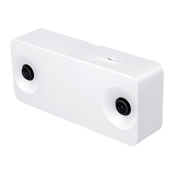
3D counting camera
SPACIOUS
CROWDED
FULL
SPACIOUS
35
/ 50
CURRENT
ALLOWED
VIVOTEK
User Guide - 1
Advertisement

Related Manuals for Vivotek SC8131


Summary of Contents for Vivotek SC8131
- Page 1 VIVOTEK Crowd Control Solution SC8131 User Guide Rev.: 1.1 SW rev.: 2.8.0.3 3D counting camera SPACIOUS CROWDED FULL SPACIOUS / 50 CURRENT ALLOWED Facing the pandemic outbreak of coronavirus, many governments imposed social distancing methods to reduce the risk of contraction. One method is to control the number of visitors inside a building while allowing people to work or purchase the necessities.
- Page 2 VIVOTEK The Social Distancing package comes with the following components: 1. 1 or multiple SC8131 3D counting cameras. 2. 1 PoE switch 3. 1 NVR * The Ethernet, HDMI cables, and HDMI extenders are user-supplied. 3D Counting camera PoE switch...
- Page 3 HDMI connection. Entrance Exit Flowpath Flowpath In addition to this document, for more information for the installation and configuration of the SC8131 camera, you can refer to its Quick Installation Guide and User Manual. User Guide - 3...
-
Page 4: Sliding Door
VIVOTEK If installed on top of a sliding door, the camera can be mounted directly above the door frame. Sliding door If installed on top of a swing door, the camera should be mounted on the ceiling inside the the door, and with a distance to the door. Its detection coverage should cover the area inside the door. - Page 5 VIVOTEK If necessary, you can purchase the AE-153 ceiling mount accessory with a high ceiling installation. Open / High Ceiling AE-153 User Guide - 5...
- Page 6 VIVOTEK Considerations Note the following when planning the camera installation: 1. The installation site must be adequately lighted for optimal accuracy with video analysis. 2. It is preferred that the camera is mounted directly above the objects to be counted. Use tools such as a spirit level to ensure the camera is installed level.
- Page 7 VIVOTEK 3. The receommended installtion position is 2.4m ~ 3.6m. Higher position is also allowed. For positions higher than 3.6m, you can also use the Zoom-in mode operation. 3-1. Use a spirit level to ensure the camera is installed level.
- Page 8 Installation Heights Below are the reference charts of the installation height and the coverage areas. Note that zooming the view is not necessary unless the camera is installed at a position higher than 3.6m. SC8131 Zoom ratio FOV (Horizontal) HFOV HFOV...
- Page 9 VIVOTEK Stitching Considerations The following applies when stitching multiple SC8131 cameras: 1. The Stitching configuration takes place on the Master camera. 1 Master camera with up to 6 Slave cameras can form a stitiching configuration. 2. All Master and Slave cameras in a Stitching configuration should be running the same firmware.
- Page 10 VIVOTEK 7. Once the Stitching configuration is done, the positioning order of peer cameras will be fixed, and you cannot change their Stitching order unless you unstitch them. Consider the following when stitching multiple cameras to form a large virtual floor plan: Height (cm)* Dist.
-
Page 11: Hardware Installation
Please do not remove the protective sheet before the installation is done. Dirty lens can seriously affect the accuracy of video analysis. 1. Jot down the camera's MAC address for later reference. SC8131 0002D10766AD 2. Plan the installation features, e.g., position and installation height. - Page 12 VIVOTEK 3. Attach the alignment sticker to a preferred position. If preferred, drill a cabling hole. See below for the diameters of it. Ø15 RJ45 Ø15mm 4. Route an Ethernet cable through the cabling hole. Ø15 RJ45 12 - User Guide...
- Page 13 VIVOTEK 5. Drill mounting holes and hammer the included anchors into the mounting holes. Ø15 RJ45 6. Secure the mounting plate to ceiling using the included screws. Ø15 RJ45 User Guide - 13...
- Page 14 VIVOTEK 7. Connect the Ethernet cable to the camera. Ø15 RJ45 RJ45 8. Align the camera with the bracket, and slide the camera to the right. The camera will then be securely mounted to the bracket. Note that the side with two LEDs is the top side, and should be aligned with the arrow mark on the mounting plate.
- Page 15 VIVOTEK To remove a camera, use a flat blade screwdriver. Press it down against the release tab from the top side and slide the camera to the left. 9. When the installation is done, remove the protective sheet. User Guide - 15...
- Page 16 The default user name and password is root / root. 10-1. Install the Shepherd utility, which helps you locate and configure your Network Camera in the local network. If your camera comes without the CD, go to VIVOTEK’s website, and locate the utility in the Downloads > Software page.
- Page 17 VIVOTEK 10-2. Run the Shepherd utility. 10-3. The program will conduct an analysis of your network environment. If access across networks is necessary, open the following ports. ■ HTTP port: default is 80 ■ RTSP port: default is 554 ■ RTP port for video: default is 5556 ■...
- Page 18 VIVOTEK 11. You can use the shortcut on the home page or open the Configuration > Application > Package management page to access the tracking and counting configuration utility. 18 - User Guide...
-
Page 19: Basic Settings
VIVOTEK Basic Settings: 1. It is recommended to configure a fixed IP for the camera. Enter Configuration > Network > General Settings to configure the camera IP. 2. It is recommended to configure a complex root password for better protection especially when your camera has access to the Internet. - Page 20 VIVOTEK 3. Enter a meaningful name for the camera. If Internet connection is available, you can configure the camera and the NVR to listen to the same NTP server for a synchronous time setting. 4. Depending on your location, configure 60Hz for countries using American National...
- Page 21 VIVOTEK 12. To start configuring the tracking and counting rules, click on Configurations. The Camera settings window will appear. Configuration - Camera settings The Camera settings page contains key parameters related to the physical characteristcs at your installation site. You need to carefully tune the parameters to acquire the best detection results.
- Page 22 VIVOTEK • Calibrate: Users can calibrate the installation height especially when installing the camera for the first time. The calibration function helps verify the correctness of the dual-lens depth map in the stereo vision. The correctness of such vision can be affected by incorrect intallation.
- Page 23 Depth view video shows significant flickering white noises in the floor area. Object trajectories are likely to be trapped in these regions For other advanced configuration settings, such as stitching, please refer to SC8131's User Manual. User Guide - 23...
- Page 24 VIVOTEK This is the view of the installation site. The white wall is unavoidable. Homogeneous and unavoidable area Shown below is the result when the Depth noise filter level is tuned up. White noises have disappeared. 24 - User Guide...
- Page 25 VIVOTEK • When to consider decreasing Depth noise filter level? If camera installation height is higher, the effective area of a person moving in the depth map will be smaller. If camera installation is higher than 3.3 meters, it is recommended to revise the following settings to minimize the possibility of losing objects' tracks.
- Page 26 VIVOTEK • An exclusive area should not be drawn on the area where people might walk through. If the body or the head of the person is shown inside the excluded area, the person can still be detected, since his feet still fall wihtin the detection zone.
- Page 27 VIVOTEK • Stream type: The following display options are available: * Single Eye Rectified HD video (up to 1280x960) * Depth view video (320x208) See the Configuration > Camera Settings page. • Show Detect Area: Select to display the effective detection area currently enabled by your analytics rules.
- Page 28 VIVOTEK Analytics: Drawing Flow Paths for Counting Draw flow path within the detection zone instead of a counting line for better acccuracy. If counting takes place on a passage, the flow path should extend and be able to cover the complete passage. Tests should be conducted on site to ensure the accuracy of counting results.
- Page 29 VIVOTEK Another method to ensure objects have been properly tracked is the use of Start-Stop map. Enable the map in the display option. Always draw a flow path between the start and stop points. Flow path is placed Flow path is placed between the start and stop points.
- Page 30 VIVOTEK Counting misses will occur if the arrows do not cover the whole passage. Shorter and more extended flow paths can help cover unexpected sharp turns. If the default sensitivity is 5, people need to travel at least 50% of the flow path length to trigger an effective count.
-
Page 31: Revision History
VIVOTEK Revision History ■ Rev. 1.0: Initial release ■ Rev. 1.1: Added Alarm, Customizable Screen Settings, and VIVOCloud support. IMPORTANT: 1. Lens cleanliness is also required because dust spots or smears on dirty lens can produce miscalculation of pixels, correlation, and movements. - Page 32 VIVOTEK Customizable Screen Configuration: 1. Enter the Social Distancing control page and click on the Settings button. Click on Appearance. 2. You can customize numerous screen panes. Click on each of the color pane. 32 - User Guide...
- Page 33 VIVOTEK There are 3 main screens: Low, Medium, and High. Select the screen for the Level of crowdedness, and then configure your screen. 3. You can refer to the image size information, e.g., that for your company's logo. Prepare the image files and save them to a USB thumbdrive.
- Page 34 VIVOTEK 4. You can change the screen information by entering a string of your preference, such as, "Masking is mandatory!." Note that you will need 3 sets of image combinations for 3 levels of occupancy. 5. When done with configuring all screen panes, click the Apply button on the upper-right of your screen.
- Page 35 VIVOTEK Configuring Alarm Notification: 1. From the Live view, enter Settings > Alarm. You need to enter the system credentials to enter the system settings page. Enter a name for your alarm configuration. 2. Select Caution occupancy reached, Full occupancy reached, and Full occupancy clear.
- Page 36 VIVOTEK 3. Select VIVOCloud app notification. This way, you can receive occupancy notices using your cell phone. Click next to proceed. 4. If preferred, configure a scheduled period of time during which the alarm notification will take effect. The default is all time.
- Page 37 VIVOTEK 5. If an alarm is triggered, e.g., the occupancy level has been breached, you can receive instant noice through the VIVOCloud app. On the VIVOCloud app connected to a Crowd control solution, you can see the Crowd control button.
- Page 38 VIVOTEK The current status will display on screen. You can constantly monitor the occupancy situation of your facility or store. 38 - User Guide...
Need help?
Do you have a question about the SC8131 and is the answer not in the manual?
Questions and answers