M&C SP Series Instruction Manual
Gas sample probe
Hide thumbs
Also See for SP Series:
- Instruction manual (59 pages) ,
- Instruction manual (34 pages) ,
- Instruction manual (19 pages)
Table of Contents
Advertisement
Quick Links
Advertisement
Table of Contents

Related Manuals for M&C SP Series


Summary of Contents for M&C SP Series
- Page 1 ® Gas Sample Probe Series SP SP2200-H/Z Instruction Manual Version 1.00.00...
-
Page 2: Table Of Contents
Contents 1 General information ........................4 2 Declaration of conformity ......................4 3 Safety instructions ........................5 4 Warranty ............................5 5 Used terms and signal indications .................... 6 6 Introduction ..........................8 6.1 Serial numbers ........................8 6.2 Power supply .......................... 8 7 ... - Page 3 Dear customer, Thank you for buying our product. In this instruction manual you will find all necessary information about this M&C product. The information in the instruction manual is fast and easy to find, so you can start using your M&C product right after you have read the manual. If you have any question regarding the product or the application, please don’t hesitate to contact M&C or your M&C authorized distributor.
-
Page 4: 1 General Information
Head Office M&C TechGroup Germany GmbH Rehhecke 79 40885 Ratingen Germany Phone: 02102 / 935 - 0 Fax: 02102 / 935 - 111 E - mail: info@mc-techgroup.com www.mc-techgroup.com GENERAL INFORMATION The product described in this manual has been built and tested in our production facility. All M&C products are packed to be shipped safely. -
Page 5: 3 Safety Instructions
SAFETY INSTRUCTIONS Follow these basic safety procedures when mounting, starting up or operating this equipment: Read this instruction manual before starting up and use of the equipment. The information and warn- ings given in this instruction manual must be heeded. Any work on electrical equipment is only to be carried out by trained specialists as per the regulations currently in force. -
Page 6: 5 Used Terms And Signal Indications
USED TERMS AND SIGNAL INDICATIONS This means that death, severe physical injuries and/or important ma- terial damages will occur in case the respective safety measures are not fulfilled. D A N G E R ! This means that death, severe physical injuries and/or important ma- terial damages may occur in case the respective safety measures are not fulfilled. - Page 7 Wear safety glasses! Protect your eyes while working with chemicals or sharp objects. Wear safety glasses to avoid getting something in your eyes. Wear protective clothes! Working with chemicals, sharp objects or extremely high tempera- tures requires wearing protective clothes. www.mc-techgroup.com SP2200-H/Z | 1.00.00...
-
Page 8: 6 Introduction
INTRODUCTION With continuous gas sampling for analytical measurements, fine dust filtration is carried out directly at the sampling point using M&C sampling probes. This means that part of the necessary maintenance of a system is concentrated at one point. This filter technology has the great advantage that dust mixtures of fine and coarse dusts are optimally retained, combined with minimum maintenance. -
Page 9: 7 Technical Data
TECHNICAL DATA ® Gas Sample Probe Series SP SP2200-H/Z Part-No 20S2017 Operating temperature Max. 180 °C [356 °F] Calibration gas valve /C Check valve, cracking pressure: >0.7 bar g Isolation valve /I Bellow valve with pneum. actuator, control pressure: 3 to 10 bar g connection: 1/8"NPT i Blow back valves /BB High flow rate check valve, cracking pressure: /BB-F... -
Page 10: 8 Dimensions
DIMENSIONS Figure 1 SP2200-H/Z front view with terminal box Figure 2 SP2200-H/Z side view SP2200-H/Z | 1.00.00 www.mc-techgroup.com... -
Page 11: 9 Applications
APPLICATIONS The probe type SP2200-H/Z is used for continuous gas sampling in processes with a high dust load (e.g. cement plants), high temperature and/or high gas humidity. Blow-back is standard (BB and BB-F) with large cross-sections in the check valves and connecting tubes. -
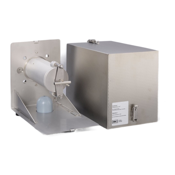
Page 12: Probe Structure
10.1 PROBE STRUCTURE The filter holder with the heating jacket on all sides forms a unit with the standard mounting flange DN 65 PN 6 and the side-mounted electrical terminal box. The heat-insulated cover hood is placed on the stainless steel angle plate mounted on the mounting flange and fastened with 2 draw latches. - Page 13 Depending on the process gas temperature and composition, probe tubes made of different materials are used with ¾" connections: Material Type Process temperature Max. length Tube (nipple) OD. Stainless steel 316Ti up to max. 600 °C 2.5 m 25 (37) mm ø Titan up to max.
-
Page 14: Receipt Of Goods And Storage
RECEIPT OF GOODS AND STORAGE The gas sample probe and any special accessories should be removed carefully from the packaging and checked immediately for completeness against the delivery note. Check the goods for any damage incurred during transport and if necessary inform your transport insurer of any damage. -
Page 15: Mounting
MOUNTING M&C SP2200-H/Z probes are designed for stationary use and if properly selected and mounted a long service life and minimum maintenance are guaranteed. Remove the probe's protection cover after opening the two draw latches. Turn the T-handle at the front end of the filter receptacle one time to the left until the retaining bolt can also be turned sideways to the left. -
Page 16: Figure 3 Sample Gas Connections Sp2200-H/Z
The pneumatic shut-off valve has a 1/8" NPT i connection thread. Here screw in a screw con- nection corresponding to the dimensions of the compressed air line and connect the com- pressed air line. Connect the test gas and the backflushing air below the mounting angle to the tube socket DN 4/6 or DN 10/12 using a suitable tube connector. -
Page 17: New Filter Housing Lid From Serial Nos. 10283
13.2 NEW FILTER HOUSING LID FROM SERIAL NOS. 10283 The sample probe series SP2000 will be delivered, starting with the serial number 10283, with a new filter housing lid lock, to make filter replacement easier. The modification consists of a T-handle „A“, which allows to fasten the filter housing lid by turning the handle clockwise and lifting up the lid by turning it anti-clockwise. -
Page 18: Electrical Connections
The following pictures show the above mentioned steps. Figure 5 Removing the filter housing lid ELECTRICAL CONNECTIONS Incorrect mains voltage can destroy the device. When connecting, W A R N I N G ! make sure that the mains voltage is correct as indicated on the nameplate! Always use the low temperature alarm contact to stop the flow of gas through the probe in the event of an alarm, protecting the down-... -
Page 19: Standard Version With Internal Capillary Tube Thermostat
Attention must be paid to the requirements of IEC 364 (DIN VDE 0100) when setting high-power electrical units with nominal voltages of up to 1000 V, together with the associated standards and stipula- N O T E ! tions. In any case we recommend the use of temperature resistant cable! A main switch and matching fuse must be provided externally! The main circuit must be equipped with a fuse corresponding to the nominal current (over current protection);... -
Page 20: Version With External Temperature Control
14.2 VERSION WITH EXTERNAL TEMPERATURE CONTROL Remove the lid of the terminal box. The electrical connection layout is located in the lid. Insert the mains cable coming from the external temperature controller (min. 3 x 1.5 mm²) through the threaded cable gland and connect to the appropriate terminals. ... -
Page 21: Calibration Gas Feed And Blow-Back
If the set point temperature setting on the control thermostat is low- ered by more than 30 °C in one step during operation, the over- temperature switch-off of the thermostat is triggered! N O T E ! When working during operation: W A R N I N G ! High surface temperatures! Touching may cause burns. -
Page 22: Maintenance
MAINTENANCE Before any maintenance work, the plant-specific and process-specific safety measures must be ob- served! Recommendations for a maintenance cycle cannot be made. Depending on your process conditions, a meaningful maintenance cycle must be determined for each specific application. An indication for a necessary probe maintenance can be a constant decrease of the sample gas quantity supplied to your analysis system. -
Page 23: Decommissioning
DECOMMISSIONING The probe should be flushed with inert gas or air to prevent condensation of aggressive components from the process gas before shutting it down, i.e. switching off the heating system. SPARE PARTS LIST Wear, tear and replacement part requirements depend on specific operating conditions. The recommended quantities are based on experience and they are not binding. -
Page 24: Appendix
APPENDIX Electrical connection diagrams More product documentation is available on our Internet catalogue: www.mc-techgroup.com Sample tubes series SP Document: 2.14 Prefilter series SP Document: 2.17 SP2200-H/Z | 1.00.00 www.mc-techgroup.com... -
Page 25: Figure 8 Electrical Connections For Sp2200-H/Z With Thermostate Controller
Figure 8 Electrical connections for SP2200-H/Z with thermostate controller www.mc-techgroup.com SP2200-H/Z | 1.00.00... -
Page 26: Figure 9 Electrical Connections For Sp2200-H/Z With Electronic Controller 70304G
Figure 9 Electrical connections for SP2200-H/Z with electronic controller 70304G SP2200-H/Z | 1.00.00 www.mc-techgroup.com...
Need help?
Do you have a question about the SP Series and is the answer not in the manual?
Questions and answers