
Related Manuals for Hydac CTM-EF-1 Series


Summary of Contents for Hydac CTM-EF-1 Series
- Page 1 CTM-EF-1x3x ContaminationTest Module - Extraction Flushing Operating and Maintenance Instructions English (translation of original instructions) Keep for future reference. Documentation no.: 4365310...
-
Page 2: Imprint
Court of Registration: Saarbrücken, HRB 17216 Executive director: Mathias Dieter, Dipl.Kfm. Wolfgang Haering Documentation Representative Mr. Günter Harge c/o HYDAC International GmbH, Industriegebiet, 66280 Sulzbach / Saar Phone: +49 6897 509 1511 Fax: +49 6897 509 1394 E-mail: guenter.harge@hydac.com © HYDAC FILTER SYSTEMS GMBH All rights reserved. -
Page 3: Table Of Contents
Content Content Imprint ......................2 Documentation Representative ..............2 Content ......................3 Preface ......................5 Technical Support ..................5 Modifications to the Product ................ 5 Warranty ...................... 5 Using the documentation ................6 General Safety Information ................6 Signal words and their meaning in the general safety information ....7 Structure of the general safety information .......... - Page 4 Content Preparing the CTM-EF for operation ............26 Positioning the CTM-EF ................26 Connecting the CTM-EF ................27 Operating filter membrane holder / Removing filter membrane ..... 28 Filter membrane holder CTMH (ContaminationTest Membrane Holder) ....................... 28 Cascading filter membrane holder CTMH ..........30 Changing the filter membrane ..............
-
Page 5: Preface
After modification or repair work that affects the safety of the product has been carried out on components, the product may not be returned to operation until it has been checked and released by a HYDAC technician. Please notify us immediately of any modifications made to the product whether by you or a third party. -
Page 6: Using The Documentation
General Safety Information Using the documentation Note that the method described for locating specific information does not release you from your responsibility of carefully reading these instructions prior to starting the unit up for the first time and at regular intervals in the future. What do I want to know? I determine which topic I am looking for. -
Page 7: Signal Words And Their Meaning In The General Safety Information
General Safety Information Any residual hazards are indicated by safety information and instructions and are described in the operating instructions. Observe all safety and warning instructions attached to the unit. They must always be complete and legible. Do not operate the unit unless all the safety devices are present. Secure the hazardous areas which may arise between the unit and other equipment. -
Page 8: Structure Of The General Safety Information
General Safety Information Structure of the general safety information All warning instructions in this manual are highlighted with pictograms and signal words. The pictogram and the signal word indicate the severity of the danger. Warning instructions listed before an activity are laid out as follows: SIGNAL WORD Type and source of danger HAZARD SYMBOL... -
Page 9: Signs Used For Giving Orders
General Safety Information Signs used for giving orders These symbols are listed for all safety information and instructions in these operating instructions which indicate particular hazards to persons, property or the environment. Wear eye protection Use protective gloves Used prohibitory signs These signs are listed for all safety information and instructions in these operating instructions which indicate particular hazards to persons, property or the environment. -
Page 10: Others Used Symbols
General Safety Information Others used symbols The following symbols found you in this operation instructions. Tip for handling the product Required tools Signs used for the required specialist personnel These symbols show the required training/knowledge for installation work and/or maintenance work. Specialist personnel –... -
Page 11: Observe Regulatory Information
General Safety Information Observe regulatory information Observe the following regulatory information and guidelines: • Legal and local regulations for accident prevention • Legal and local regulations for environmental protection • Country-specific regulations, organization-specific regulations CTM-EF 1x3x Series Page 11 / 52 BeWa CTM-EF 1x3x 4365310 en-us 2018-06-06.docx 2018-06-06... -
Page 12: Proper/Designated Use
Any use extending beyond or deviating therefrom shall not be considered intended use. HYDAC FILTER SYSTEMS GMBH will assume no liability for any damage resulting from such use. Proper or designated use of the product extends to the following: •... -
Page 13: Improper Use Or Use Deviating From Intended Use
Improper Use or Use Deviating from Intended Use Any use extending beyond this or deviating therefrom shall not be considered intended use. HYDAC Filter Systems GmbH will assume no liability for any damage resulting from such use. The user alone, shall assume any and all associated risk. -
Page 14: Qualifications Of Personnel / Target Group
General Safety Information Qualifications of personnel / target group Staff who work with the powerpack must be aware of the dangers involved, must be over the age of 14 and must be without any physical impediments in regard to the industrial environment. These operating instructions are intended for: Auxiliary personnel: Auxiliary personnel: such persons have been instructed about the product... - Page 15 General Safety Information Activity Person Knowledge • Proof of knowledge of Transport / storage Forwarding agent cargo securing instructions Specialist • Safe handling/operation personnel of hoisting and lifting equipment • Safe handling/use of Hydraulic / electrical Specialist installation, personnel tools •...
-
Page 16: Wear Suitable Clothing
General Safety Information Wear suitable clothing Loose-fitting clothing increases the risk of being caught or being drawn in on rotating parts, and the risk of getting caught on protruding parts. You can be severely injured or killed. Depending on the test liquid, protective gloves and eye protection are to be worn. -
Page 17: Transporting The Module
Transporting the module Transporting the module The module is shipped from the factory in a wooden box with the corresponding securing devices. Pack the assembly for further transport in this wooden box. Alternatively, place the assembly on a pallet of sufficient size using a forklift. -
Page 18: Decoding The Model Code Label
Decoding the model code label Decoding the model code label Details for identifying the filtration unit can be found on the name plates on the unit and the components. Item -> Description -> Name plate for module -> Supply voltage, power supply, power consumption Model ->... -
Page 19: Checking The Scope Of Delivery
Checking the scope of delivery Checking the scope of delivery The ContaminationTest Module CTM-EF comes packed and ready to be connected. Before commissioning, please check the scope of delivery to make sure it has not been damaged during transport and that it is complete. Designation ContaminationTest Module CTM-EF Technical documentation, consisting of:... -
Page 20: Module Dimensions
Module dimensions Module dimensions All dimensions in mm. CTM-EF 1x3x Series Page 20 / 52 BeWa CTM-EF 1x3x 4365310 en-us 2018-06-06.docx 2018-06-06... -
Page 21: Functional Principle
Functional principle Functional principle The CTM-EF module is an extraction module for component sampling using rinse extraction. This module may be used with the CTM-SC-1xxx, CTU 1x4x-x-x-F, CTU 1x4x-x-x-A supply modules. These components are rinsed off in a test liquid with a defined cleanliness. At the end of the sampling process, the entire liquid with its particle load is sucked via the membrane retainer. -
Page 22: Blank Values
Functional principle Blank values The achievable blank values depend largely on the ambient conditions, the frequency of use, the rinsing volume, etc. Parameters for cleaning Automatic Manual Center CTM-EF 12xx eliminated nozzle Center CTM-EF 14xx eliminated nozzle Center Flat CTM-EB 12xx nozzle spray... -
Page 23: Parameters For Determining Blank Values
Functional principle Parameters for determining blank values Achievable maximum values Center CTM-EF 12xx nozzle Center CTM-EF 14xx nozzle Flat CTM-EB 12xx spray Flat CTM-EB 14xx spray 14xx Flat CTM-EB (Q8) spray Flat CTM-EB 16xx spray Flat CTM-EB 18xx spray Flat CTM-EB 19xx spray... -
Page 24: Parameters For Rinsing
Functional principle Parameters for rinsing Installation Pressure Device type Volume in l Nozzle size [bar] Center CTM-EF 12xx nozzle Center CTM-EF 14xx nozzle CTM-EB 12xx Flat spray CTM-EB 14xx Flat spray CTM-EB 14xx (Q8) Flat spray CTM-EB 16xx Flat spray CTM-EB 18xx Flat spray... -
Page 25: Components Of The Module
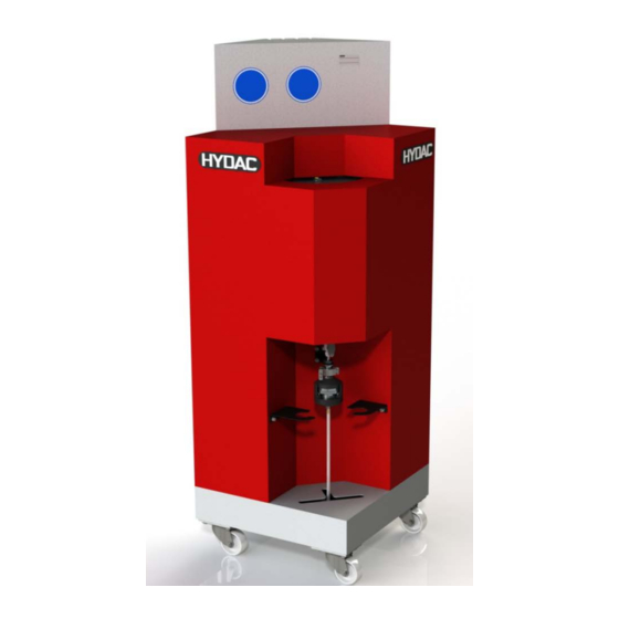
Components of the module Components of the module Item Designation Reservoir Cover Ball valve Filter membrane holder Control plug Connection hoses A I B I R Sliding grip Caster Connections hoses of test item A´ I R´ Filter membrane holder support CTM-EF 1x3x Series Page 25 / 52 BeWa CTM-EF 1x3x 4365310 en-us 2018-06-06.docx... -
Page 26: Preparing The Ctm-Ef For Operation
Preparing the CTM-EF for operation Preparing the CTM-EF for operation Positioning the CTM-EF The CTM-EF can be moved into the required location on its own casters. The CTM-EF has 4 casters. Before pushing, release the hand brake on the casters. When you have positioned and aligned the CTM-EF, set the brakes on the casters. -
Page 27: Connecting The Ctm-Ef
Preparing the CTM-EF for operation Connecting the CTM-EF The CTM-EF is delivered ready-to-connect. Before starting it up please note or check the following: • Read the installation and maintenance instructions for this module, the CTM-SC-1xxx, CTU 1x4x-x-x-F, CTU 1x4x-x-x-A, the instruction manuals for the CTM-SC-1xxx, CTU 1x4x-x-x-F, CTU 1x4x-x-x-A software carefully. -
Page 28: Operating Filter Membrane Holder / Removing Filter Membrane
Operating filter membrane holder / Removing filter membrane Operating filter membrane holder / Removing filter membrane Filter membrane holder CTMH (ContaminationTest Membrane Holder) The design presses the filter membrane in the lower part (2) of the filter membrane holder function-tight to the upper part. The CTMH filter membrane holder has three height positions for threefold cascading. - Page 29 Operating filter membrane holder / Removing filter membrane CAUTION "G60 Spezial" test liquid Health hazard ► Make sure that there is adequate ventilation. ► Always wear protective gloves. ► Always wear eye protection. NOTICE Test liquid flows out Danger of slipping and falling ►...
-
Page 30: Cascading Filter Membrane Holder Ctmh
Operating filter membrane holder / Removing filter membrane Cascading filter membrane holder CTMH Cascade filter membranes as shown in the following illustration: Item Designation Coupling Hose connection Diffuser (A diffuser ensures that the analysis liquid is evenly distributed over the entire filter membrane) Upper part of the filter membrane holder... -
Page 31: Changing The Filter Membrane
Changing the filter membrane Changing the filter membrane The ball valve on the filter membrane holder serves as an emergency isolation valve. Carrying out the replacement Before you remove the filter membrane, the analysis liquid must have been completely sucked away. Hold the holder with one hand on the lower part. - Page 32 Changing the filter membrane Pull down the lower part slightly. Then pull it fully through the opening created. Remove the filter membranes from the cascade for further analysis and mark them as given in the chapter on page Fit a new filter membrane onto the supporting sieve.
- Page 33 Changing the filter membrane Place the lower part horizontally in the upper part together with the filter membranes. Lift the lower part vertically under the upper part. The position of the screen must match the number of cascades. If two cascades are mounted, the screen must be moved to the...
- Page 34 Changing the filter membrane If three cascades are mounted, the screen must be moved to the uppermost position. Tighten the lock 90° in the clockwise direction. Do not use any tools! CTM-EF 1x3x Series Page 34 / 52 BeWa CTM-EF 1x3x 4365310 en-us 2018-06-06.docx 2018-06-06...
-
Page 35: Labeling The Filter Membrane
Changing the filter membrane Labeling the filter membrane Label the filter membrane that you just removed using a clear & logical system. An example of labeling filter membranes: xyz-1-A-005 Current sample series, component designation Number of membranes created for a measurement series If several equivalent rinsing operations are to be performed for a component, A, B, C and Z are used for creating a random sample. -
Page 36: Starting Up The Module
Starting up the module Starting up the module Clean-Room Conditions in the Analysis Chamber - Rinsing of the inner chamber Before starting a contamination test series, the analysis chamber has to be cleaned in a defined manner by volume or time using the inner chamber rinsing program. -
Page 37: Performing Maintenance
Performing maintenance Performing maintenance WARNING The system is pressurized Danger of bodily injury ► The system must be depressurized before performing any work on it. WARNING "G60 Spezial" test liquid Fire hazard ► Fires, naked lights and smoking prohibited CAUTION "G60 Spezial"... -
Page 38: Maintenance Work
Performing maintenance Maintenance work The maintenance and servicing to be performed periodically is described in the following. The products serviceability, operational reliability and service life substantially depend on performing maintenance and servicing work regularly and carefully. Check all hoses for leaks or signs of brittleness Visually inspect the electrics. -
Page 39: Clean The Diffuser On The Filter Membrane Holder
Performing maintenance Clean the diffuser on the filter membrane holder Clean the filter membrane holder at least once a week. Open the coupling (1) and remove the diffuser (3). Clean the diffuser (3) by blowing it out with compressed air. Put the diffuser into the filter membrane holder and screw the coupling (1) finger tight. -
Page 40: Finding Spare Parts
Finding spare parts Finding spare parts Use only original spare parts and accessories. When ordering spare parts, always specify the designation of the unit (type, material no., serial no., year of manufacture). Description Part no. Qty.** Filter membrane 5 µm, ∅ 47 mm 309376 Colour: White, surface smooth, 1 pckg. -
Page 41: Decommissioning The Product
Decommissioning the product Decommissioning the product Empty the product fully, including all the components, before decommissioning. Pull out the power plug, and securely fasten the hoses and power cord to the product. Shutting down the product See chapter "Decommissioning the product" Disposing of the product After dismantling the product and separating its various materials into categories, dispose of all parts in an environmentally friendly manner. -
Page 42: Technical Data
Technical Data Technical Data Dimensions Height = 1448 mm Width = 500 mm Depth = 500 mm ≈ 53 kg Empty weight Nominal volume EF 1230: 5 liters EF 1430: 8 liters Voltage 24 V DC Wattage 15 W Protection class to DIN IP 54 400050 Permitted ambient... -
Page 43: Attachment
Fax: +49 6897 509 9046 E-mail: filtersystems@hydac.com For repair work or complaints, please contact our central customer service department: HYDAC SYSTEMS & SERVICES GMBH Friedrichsthaler Straße 15, Werk 13 66540 Neunkirchen-Heinitz Phone: +49 6897 509 883 Fax: +49 6897 509 324 E-mail: service@hydac.com... -
Page 44: Hydraulic Diagram
Attachment Hydraulic diagram CTM-EF 1x3x Series Page 44 / 52 BeWa CTM-EF 1x3x 4365310 en-us 2018-06-06.docx 2018-06-06... - Page 45 Attachment Item Designation Quick-action coupling "A" Quick-action coupling "B" Quick-action coupling "R" Test item port A' Test item port R' Reservoir Inner chamber flushing Breather filter Membrane holder Level sensor Ball valve Test item CTM-EF 1x3x Series Page 45 / 52 BeWa CTM-EF 1x3x 4365310 en-us 2018-06-06.docx 2018-06-06...
-
Page 46: Model Code
Attachment Model code - EF 0 - Z - Z - Z / - Product CTM = ContaminationTest Module Series = Extraction Flushing Analysis chamber dimensions = Volume 5 liters = Volume 8 liters Version = Version 2009 = Version 2018 Test liquid = solvent class A III (flash point >60°C, explosion limit >0.6 % by... -
Page 47: Explanation Of Terms And Abbreviations
Attachment Explanation of terms and abbreviations An explanation of terms and abbreviations follows below: °C Degrees Celsius abs. Absolute (e.g. in pressure specifications) Alternating current Air Bleed Ventilation / air bleed port Analysis fluid After spray extraction load test liquid with particles up to the filter membrane. - Page 48 Attachment extraction Inlet INLET Inlet Meter Maximum mbar Millibar (1 mbar = 0.001 bar) Minimum Millimeter Nitrile rubber Newton meters (torque specification) Switched off Switched on Outlet OUTLET Outlet Test liquid Fluid for general operation. (flushing fluid / analysis fluid). Sec.
-
Page 49: Index
Attachment Index Inlet 48 INLET 48 installation 10, 15, 26, 27 IP 42 Accessories 40 accident prevention 11, 16 ambient temperature 42 Analysis 36, 46, 47 Auxiliary personnel 14 Level sensor 40, 45 Breather filter 40, 45 Maintenance 1, 15, 38, 47 Manufacturer 2 Measures 8 Model code 18, 46... - Page 52 HYDAC FILTER SYSTEMS GMBH Industriegebiet Postfach 1251 66280 Sulzbach/Saar 66273 Sulzbach/Saar Germany Germany Tel: +49 6897 509 01 Board no. Fax: +49 6897 509 9046 Technology Fax: +49 6897 509 577 Sales Internet: www.hydac.com E-mail: filtersystems@hydac.com...
Need help?
Do you have a question about the CTM-EF-1 Series and is the answer not in the manual?
Questions and answers