
Subscribe to Our Youtube Channel
Related Manuals for ADLINK Technology Q7-BT


Summary of Contents for ADLINK Technology Q7-BT
- Page 1 Q7-BT Technical Reference Qseven Computer On Module with ® Intel Atom™ E3800 Series Processors Manual Rev.: Revision Date: June 18, 2018 Part Number: 50-1Z202-1020 Leading EDGE COMPUTING...
-
Page 2: Preface
Audience This manual provides reference only for computer design engineers, including but not limited to hardware and software designers and applications engineers. ADLINK Technology, Inc. assumes you are qualified to design and implement prototype computer equipment. Preface... - Page 3 Q7-BT Environmental Responsibility ADLINK is committed to fulfill its social responsibility to global environmen- tal preservation through compliance with the European Union's Restriction of Hazardous Substances (RoHS) directive and Waste Electrical and Elec- tronic Equipment (WEEE) directive. Environmental protection is a top prior- ity for ADLINK.
- Page 4 Important Safety Instructions For user safety, please read and follow all Instructions, WARNINGs, CAUTIONs, and NOTEs marked in this manual and on the associated equipment before handling/operating the equipment. Read these safety instructions carefully. Keep this manual for future reference. ...
-
Page 5: Table Of Contents
Q7-BT Table of Contents Preface ..........................ii 1 Product Overview ......................1 Description ..........................1 Features..........................2 Block Diagram........................3 Specifications......................... 4 1.4.1 Physical ..........................4 1.4.2 Electrical ..........................4 1.4.3 Environmental........................4 1.4.4 Mechanical.........................5 1.4.5 Power..........................6 1.4.6 Cooling ..........................6 Getting Started........................7 2 Hardware ........................... - Page 6 4 Utilities ..........................27 BIOS............................ 27 4.1.1 Configuring the BIOS ...................... 27 4.1.2 Main screen of the BIOS ....................27 4.1.3 Advanced Settings screen ....................29 4.1.4 Security screen ....................... 37 4.1.5 Boot screen ........................38 4.1.6 Save & Exit screen......................38 SEMA functions........................
-
Page 7: Product Overview
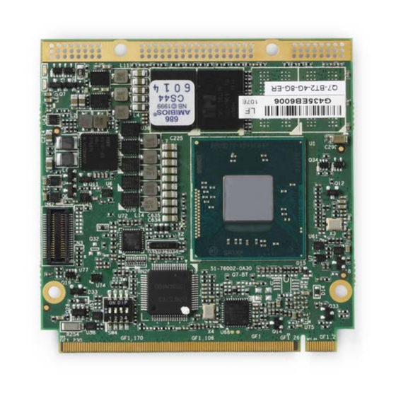
With mechanical dimensions as small as 70mm width, 70mm length, and 2.3mm of over- all height, Qseven ranks as the smallest COM standard currently available. The Q7-BT module utilizes the E3800 SoC for contemporary, high-bandwidth interfaces such as PCI Express, USB, Gigabit Ethernet, SATA, and HD Audio. The module generates its own LVDS, TMDS, and DisplayPort video signals using DDI output from the SoC. -
Page 8: Features
1.2 Features Intel Atom™ E3800 Series, single, dual, or quad-core SoC (System-on-Chip) with inte- grated memory, graphics, and I/O. See the E3800 data sheet at the Intel website. E3845 10W TDP, 1.91GHz Quad-Core/1333 MT/s with Gfx 542/792 MHz, Turbo ... -
Page 9: Block Diagram
Q7-BT 1.3 Block Diagram LVDS 18/24bit dual LV DS DDI0 RTD2136 DDR3L DDR 3L 1066/1333MHz DDI1 (DP, TMDS) Memory down 2/4GB HD Audio eM M C PCIe x1 eMMC i210IT (Option) 3x PCIe x1, PCIe port 1,2,3 SATA-SSD SATA (Option) -
Page 10: Specifications
1.4 Specifications 1.4.1 Physical Table 1-1 lists the physical dimensions of the module. Table 1-1: Weight and Footprint Dimensions Overall height is measured from the upper board Dimension Measurement surface to the top of the highest permanent Weight 0.025 kg component on the upper board surface. -
Page 11: Mechanical
Q7-BT 1.4.4 Mechanical Figure 1-3 provides the mechanical dimensions of the Q7-BT. Figure 1-3: Mechanical dimensions (top side) ADLINK strongly recommends plastic spacers instead of metal spacers for mounting the board. Metal spacers create the possibilities of short cir- cuits with the components located around the NOTE: mounting holes, which can ruin the board. -
Page 12: Power
BIT (Burn-In Test) operating configuration - Windows 8.1; Intel TAT tool 1.4.6 Cooling The Q7-BT is designed to operate at its maximum CPU speeds of and 1.91GHz and 1.46GHz requires a thermal solution to cool the SoC. ADLINK offers a heat spreader as one part of the cooling solution. -
Page 13: Getting Started
Q7-BT Figure 1-4: Heat Spreader mounting dimensions (top side) Getting Started Mount the Q7-BT to the carrier as illustrated in Figure 1-5, which provides a profile view of the module mounted to the carrier with dimensions. Qseven Module PCB Qseven Connector 2.00... - Page 14 If you need to load the BIOS default values, they can be automatically loaded at boot time. The Q7-BT boots from CD drives, USB sticks, hard disks, or µSD-Cards. Provided that any of these is connected and contains a valid operating system image, the display then shows the boot screen of your operating system.
-
Page 15: Hardware
SMBus slave device addresses on the board. 2.1 Major Components (ICs) Table 2-1 lists the major integrated circuits on the Q7-BT, including a brief description of each IC. Figure 2-1 and Figure 2-2 show the locations of the major ICs. - Page 16 Table 2-1:Major Integrated Circuit Descriptions and Functions (Continued) Chip Type Mfg. Model Description Function DDR3L On-board DDR3L, Provides SDRAM 1.35V, 4Gb, high-speed data (U24, U25, 32Mx16x8, non-ECC transfer U26, U27 [U24 System Memory and U27 on bottom side; Micron • MT41K128M16 •...
-
Page 17: Connectors, Switches, And Leds
Q7-BT Key: - GbE Controller U19 U20 - BIOS 0 - BIOS 1 - DDR3L SDRAM - DDR3L SDRAM - eMMC NAND Flash - SSD NAND, SATA P229 Figure 2-2: Component Locations (Bottom Side) 2.2 Connectors, Switches, and LEDs Table 2-2 describes the connectors, switches, and LEDs shown in Figure 2-3 and Figure 2-4. - Page 18 Table 2-2: Module Connector Description (Continued) Board Connector# Description Access 4-pin dip switch for the following BIOS control functions. (Diptronics, DHNF-04-T-Q-T/R) • Pin 1 = Loading BIOS setup defaults at Boot Up (OFF - default) • Pin 2 = Enabling WDT (OFF - default) •...
-
Page 19: Component Features
This section further describes the supported features of the Q7-BT major on-board components. 2.3.1 The Q7-BT product family offers multiple versions of the Intel Atom E3800 Series CPU, Sys- tem-on-Chip (SoC): the E3815 (Single Core), the E3825 (Dual Core), the E3826 (Dual Core), and the E3845 (Quad Core). -
Page 20: Sata Ssd (Solid State Drive)
2.3.4 SATA SSD (Solid State Drive) The Q7-BT features an optional SATA SSD, soldered directly to the board and routed through the SATA1 port. For more information, refer to the SSD data sheet at the Greenliant website. 2.3.5 SMBus Slave Addresses Figure 2-1 lists the corresponding slave addresses of the devices on the SMBus. -
Page 21: Interfaces
Q7-BT Interfaces This section provides descriptions of the interfaces and signals within the Q7-BT P-S (Primary- Secondary) Qseven connector. Refer to the Qseven specification at: http://www.sget.org/standards/qseven.html for complete definitions of all the Qseven interfaces. The Q7-BT P-S (Primary-Secondary) Qseven connector provides the following interfaces: ... -
Page 22: 18/24-Bit Lvds Lcd
CODEC can be implemented at the same time. 3.5 PCI Express (PCIe) The CPU features four PCIe x1 ports, and the Q7-BT module uses three of them for the PCIe interface and one of them for the Gigabit Ethernet interface. The PCIe interface supports the PCIe Base Specification 2.0 with a maximum signal rate of 5 GT/s and can be configured to sup-... -
Page 23: Usb Ports
NOTE: 3.8 SATA The SATA interface provides two ports through the SATA0 and SATA1 pins on the Q7-BT con- nector. The interface supports 1.5Gb/s and 3.0Gb/s. One of the SATA ports is shared with the PCIe Mini Card socket on the baseboard. -
Page 24: Qseven Interface Signals
3.16 Qseven Interface Signals Table 3-1 provides the pin signals for the Qseven connector. Refer to the Qseven specification http://www.sget.org/standards/qseven.html for further definitions of the Qseven signals. Table 3-1: Q7 Interface (GF1) Signal Descriptions Pin # Primary (Top Side) Pin # Secondary (Bottom Side) GBE_MDI3- (Media Dependent Interface GBE_MDI2- (Media Dependent Interface... - Page 25 Q7-BT Table 3-1: Q7 Interface (GF1) Signal Descriptions (Continued) Pin # Primary (Top Side) Pin # Secondary (Bottom Side) SLP_BTN# (Sleep button. Low active LID_BTN# (LID button. Low active signal signal used by the ACPI operating system used by the ACPI operating system to...
- Page 26 Table 3-1: Q7 Interface (GF1) Signal Descriptions (Continued) Pin # Primary (Top Side) Pin # Secondary (Bottom Side) Not Connected RSVD HDA_SYNC (Serial Bus Audio SMB_CLK (Clock line of System Synchronization.) Management Bus.) HDA_RST#(HD Audio/AC'97 Codec SMB_DAT (Data line of System Reset.) Management Bus.) HDA_BITCLK (HD Audio/AC'97 24 MHz...
- Page 27 Q7-BT Table 3-1: Q7 Interface (GF1) Signal Descriptions (Continued) Pin # Primary (Top Side) Pin # Secondary (Bottom Side) USB_CC (USB Client Connect pin. If USB_ID (USB ID pin. Configures the mode USB Port 1 is configured for client mode, of the USB Port 1.
- Page 28 Table 3-1: Q7 Interface (GF1) Signal Descriptions (Continued) Pin # Primary (Top Side) Pin # Secondary (Bottom Side) eDP0_TX3- (option) / LVDS_A3- LVDS_B3- (LVDS secondary channel (LVDS primary channel differential pair 3. differential pair 3.) Embedded Display Port primary channel differential pair 3.) eDP0_AUX+ (option) / LVDS_A_CLK+ LVDS_B_CLK+ (LVDS secondary channel...
- Page 29 Q7-BT Table 3-1: Q7 Interface (GF1) Signal Descriptions (Continued) Pin # Primary (Top Side) Pin # Secondary (Bottom Side) DP_LANE0+/TMDS_LANE2+ HDMI_CTRL_DAT (DDC based control (DisplayPort differential pair lines lane 0, signal [data] for HDMI shared with TMDS differential pair lines device.
- Page 30 Table 3-1: Q7 Interface (GF1) Signal Descriptions (Continued) Pin # Primary (Top Side) Pin # Secondary (Bottom Side) SERIRQ (Serialized Interrupt.) Not Connected VCC_RTC (3 V backup cell input. SPKR (Output for audio enunciator, the VCC_RTC should be connected to a 3V “speaker”...
-
Page 31: Debug (Db40) Connector Signals
Q7-BT 3.17 Debug (DB40) Connector Signals Table 3-1 lists the pin signals of the CN1 connector, which provides 40 pins, 1 row, consecutive sequence with 0.02" (0.50mm) pitch. Table 3-1: Debug Interface Signals (CN2701) Pin # Interface Signal RESVD SMC_STATUS... -
Page 32: Mipi Csi Camera Connector Signals
3.18 MIPI CSI Camera Connector Signals Table 3-2 lists the pin signals of the CN3 connector, which provides 40 pins, 2 rows, consecutive sequence with 0.02" (0.50mm) pitch. Table 3-2: MIPI CSI Camera Interface Signals (CN3) Pin # Signal Pin # Signal MCSI_CAM0PWR# MCSI_CAM1PWR#... -
Page 33: Utilities
Q7-BT. 4.1 BIOS The Q7-BT features an AMI BIOS. The default settings provide a “ready to run” system, even without a BIOS setup backup battery. The BIOS is located in flash memory and can be easily updated with software under DOS. - Page 34 Main Screen > (Scrolled to Bottom) Utilities...
-
Page 35: Advanced Settings Screen
Q7-BT 4.1.3 Advanced Settings screen The main screen of “Advanced Settings” provides configuration settings for CPU, Graphics, SATA, USB, SDIO, Network, Audio, PCI/PCIe, Devices, ACPI, Serial, Thermal, Security, Miscel- laneous, and SIO. Inappropriate values for any of the following advanced settings below may cause the system to malfunction. - Page 36 Advanced > CPU Advanced > Graphics Utilities...
- Page 37 Q7-BT Advanced > SATA Advanced > USB Utilities...
- Page 38 Advanced > SDIO Advanced > Network Utilities...
- Page 39 Q7-BT Advanced > Audio Advanced > PCI-PCIe Utilities...
- Page 40 Advanced > Devices Advanced > ACPI Utilities...
- Page 41 Q7-BT Advanced > Serial Advanced > Thermal Utilities...
- Page 42 Advanced > Security Advanced > Miscellaneous Utilities...
-
Page 43: Security Screen
Q7-BT Advanced > SIO 4.1.4 Security screen Utilities... -
Page 44: Boot Screen
4.1.5 Boot screen If more than one drive is attached to the Q7-BT, you can select from the first “Boot Configura- tion” screen the boot order in which the drives are scanned for a bootable OS image. 4.1.6 Save & Exit screen... -
Page 45: Sema Functions
Q7-BT 4.2 SEMA functions Under the management of the BMC chip (Board Management Controller), the SEMA utility (Smart Embedded Management Agent) provides system control and failure protection—count- ing, monitoring, and measuring hardware and software events, from which the SoC can trigger corrective commands. -
Page 46: Board Specific Sema Functions
Use Main Current Function Main Current The BMC of the Q7-BT implements a Current Monitor. The current can be read by calling the SEMA function “Get Main Current”. The function returns four 16-bit values divided in Hi-Byte (MSB) and Lo-Byte (LSB). These four values represent the last four currents drawn by the board. -
Page 47: Watchdog Timer
The BMC Flags register returns the last detected exception code since power up. 4.3 Watchdog Timer The Q7-BT features three separate Watchdog Timers. One of them is integrated in the SoC and two are provided by the BMC (managed by the SEMA). - Page 48 This page intentionally left blank. Utilities...
-
Page 49: Appendix A Technical Support
Q7-BT Appendix A Technical Support ADLINK Technology, Inc. provides a number of methods for contacting Technical Support listed in Table A-1 below. Requests for support through Ask an Expert are given the highest priorities, and usually will be addressed within one working day. - Page 50 Table A-1: Technical Support Contact Information (Continued) Address: Hans-Thoma-Strasse 11 D-68163 Mannheim, Germany Tel: +49-621-43214-0 Fax: +49-621 43214-30 Email: emea@adlinktech.com Please visit the contact page using the web site link shown above for information on how to contact the ADLINK regional office near- est you.
Need help?
Do you have a question about the Q7-BT and is the answer not in the manual?
Questions and answers