
Related Manuals for Afag LM 20


Summary of Contents for Afag LM 20
- Page 1 Linear modules LM 20 and LM 25 Declaration of Incorporation Module Information Montage Instructions Maintenance Instructions “Translation” of the Original Montage Instructions © Copyright by Afag Automation AG...
- Page 2 Linear Linear modules modules LM 20 LM 25 Version of this documentation: LM 20- LM 25-OI-vers. 3.1 gb. 20190314 Symbols: Assembly and initial start-up must be carried out by qualified Personnel only and according to these Montage Instructions. DANGER Indicates an immediate threatening danger.
-
Page 3: Table Of Contents
2.1.3 Mounting for the modules (centering bushings) ..........8 2.1.4 Tightening Torques for bolts ................8 2.1.5 Installation of the LM 20 / LM 25 in a facility ..........9 2.1.6 Slide unit load factors LM 20 ................ 10 2.1.7 Slide unit load factors LM 25 ................ 11 2.1.8 Preferred combinations for the LM 20 Modules ........... - Page 4 3.3.1 Preparation for Commissioning ..............33 4.0.0 Maintenance Instructions ................. 34 4.1.0 Maintenance and servicing of the LM 20/25 linear module compact .... 34 4.1.1 Servicing ...................... 35 4.1.2 Accessories to the LM-linear modules ............36 4.1.3 Troubleshooting ................... 37 4.1.4 Disassembly and repair ................
-
Page 5: Ec Declaration For Incorporation (Document Original)
EC directive: 2006/42 / EC. Norme: EN ISO 12100:2010 (German Version) Agent: For the compilation of the technically relevant documents: Niklaus Röthlisberger, Products Manager Afag Automation AG, CH-4950 Huttwil Place, Date: Huttwil, 14.03.2019 Siegfried Egli Niklaus Röthlisberger Producte Manager GT... -
Page 6: Module Information
2.1.0 Transport and Storage (packing and unpacking) CAUTION The LM 20 module is packed in the original cardbord box if the module is not handled properly it may fall out of the box when unpacking and cause injuries to limbs or squeeze your fingers. -
Page 7: Mounting Variants For Lm 20 / Lm 25 Module
Mounting plates on the front if the reason the body is used as a sled. (M6 Thread). 2.1.2 Mounting variants for LM 20/25 The LM can be combined in any required position to all other Afag pick and place module. -
Page 8: Mounting For The Modules (Centering Bushings)
The screwed to be used for assembly must at least satisfy the following conditions: Standard: VDI 2230 Strength: class 8.8 Surface: galvanized blue, oiled or greased Thread Torque 1,1 … 1,3 Nm 2,5 … 2,9 Nm 4,9 … 5,8 Nm 8,5 ... 9,9 Nm LM 20- LM 25-OI-vers. 3.1 gb. 20190314... -
Page 9: Installation Of The Lm 20 / Lm 25 In A Facility
2.1.5 Installation of the LM 20 / LM 25 in a facility This is an incomplete machine Assembly of the LM 20/25 module in a system The series of the LM - Linear modules is used for the linear, smooth movement of rigidly mounted loads under the ambient and operating conditions defined for this module, see Technical data. -
Page 10: Slide Unit Load Factors Lm 20
2.1.6 Slide unit load factors LM 20 LM 20- LM 25-OI-vers. 3.1 gb. 20190314... -
Page 11: Slide Unit Load Factors Lm 25
2.1.7 Slide unit load factors LM 25 LM 20- LM 25-OI-vers. 3.1 gb. 20190314... -
Page 12: Preferred Combinations For The Lm 20 Modules
2.1.8 Preferred combinations for the LM 20 Modules LM 20- LM 25-OI-vers. 3.1 gb. 20190314... -
Page 13: Preferred Combinations For The Lm 25 Modules
2.1.9 Preferred combinations for the LM 25 Modules LM 20- LM 25-OI-vers. 3.1 gb. 20190314... -
Page 14: Montage Instructions (Document Original)
These operating instructions apply to: Product: Linear module (pneumatic) Types: LM 20/30; LM 20/60, LM 20/90, LM 20/150, LM 20/200 LM 25/60, LM 25/120, LM 25/200 This is an incomplete machine Who installs this incomplete machine or assemble with other machines, a risk... -
Page 15: Symbols
The LM 20/25 module can be installed in the horizontal or vertical position. Modifications on the LM 20 / LM 25 linear module that are not described in these Montage Instructions or have not been approved in writing by Afag Automation AG are not permitted. -
Page 16: Description Of The Lm 20/25 Module
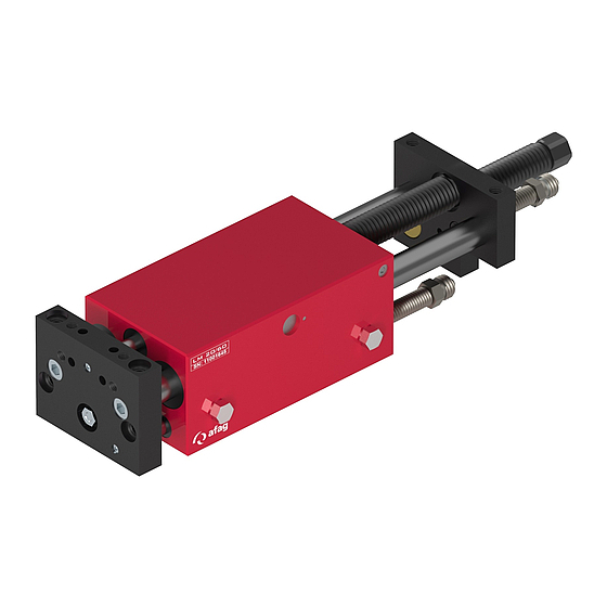
3.1.3 Description of the LM 20/25 module The LM 20/25 consists of the base body (1) with pneumatic connections (6) and cylinder and the front plates (2) and back plates (3). The stop positions are set by means of a stop screw (4). To query the limit positions an inductive sensor with a diameter of 6.5 mm (not included in the scope of delivery) -
Page 17: Intended Use
3.1.4 Intended use The series of the linear module LM 20 and LM 25 is used for the linear movement of rigidly mounted loads in non-explosions harzadous ambient and operating conditions that are specified for this module; see catalogue technical. -
Page 18: Warranty
The Linear modules are exclusively for the linear movement in any position of payloads at the forehead to record maximum 2-8 kg (LM 20) and 4-9 kg (LM 25) designed, (see technical data). They can also be used in combination with other modules than Pick and Place machines, the permissible load capacities should, however, not be exceeded. -
Page 19: Dimension Drawing Lm 20
3.1.7 Dimension drawing LM 20 LM 20- LM 25-OI-vers. 3.1 gb. 20190314... -
Page 20: Technical Data Of The Lm 20
3.1.8 Technical data of the LM 20 LM 20- LM 25-OI-vers. 3.1 gb. 20190314... -
Page 21: Dimension Drawing Lm 25
3.1.9 Dimension drawing LM 25 LM 20- LM 25-OI-vers. 3.1 gb. 20190314... -
Page 22: Technical Data Of The Lm 25
3.2.0 Technical data of the LM 25 LM 20- LM 25-OI-vers. 3.1 gb. 20190314... -
Page 23: Function Of The Module Linear
3.2.1 Function of the module linear The linear module LM 20/25 pneumatic devices are operated for longitudinal movements of 0 a 200 mm stroke. All modules are customer order is delivered ready for installation. An air-operated double-acting piston generates the longitudinal motion. -
Page 24: Pneumatic Connection Lm 20 / Lm 25
3.2.2 Pneumatic connection LM 20 / LM 25 At the base are located on the right and left sides each 2 pneumatic connectors M5, (LM 25, G 1/8’’) The non-pneumatic connections must be used with the supplied screw cap fitted with an airtight lid. -
Page 25: Adjusting The Linear Modules
AS 08/40 (1) and two shock absorbers SD 14/16 (2) to end setting. (Fig. 17) Base plate LM 20/25; with the help of the base plate (3) can realize a portal module. The base plate also serves to stabilize and the customer may be edited. -
Page 26: Stroke And Stop Screw Adjusting
4. P2 Air to enter. The Sleigh (9) of the LM goes to the stop screw (2). 5. Front position X of the stroke by adjusting the stop screw (2) determine, after locking nut (8) secure.(Fig. 22) LM 20- LM 25-OI-vers. 3.1 gb. 20190314... -
Page 27: Adjusting Shock Absorber
(8) secure. 7. Shock absorber (2) clockwise two ambulatories unscrew (1) and protect with mother. CAUTION If shock absorbers are used as an as an attack, they can be damaged and unusable. LM 20- LM 25-OI-vers. 3.1 gb. 20190314... -
Page 28: Assembly For The Accessory 3Rd. Position
The 3rd Position is different in height X between the workpiece and workpiece- transfer absorption in. (Fig. 24-2) 3. Position on the example: LM 20 1. Nut (1) solve and shock absorbers (2) counter-clockwise in about 5 affable unscrew. (Fig.24-1). -
Page 29: Assembly The Intermediate Stop (Za 20/25)
3.2.7 Assembly the intermediate stop (ZA 20/25) The intermediate stop ZA 20/25 is an add-on module for the linear series LM 20/25, which is an arbitrary intermediate position within the entire stroke range of the linear Module allows. The intermediate stop may be of the symmetric structure to the front to rear as acting on the base plate ZA installed. - Page 30 Linear Modules (ZA) Maintenance unit One-way restrictor Compressed air connection Directional valve (Standard 5/2) LM 20- LM 25-OI-vers. 3.1 gb. 20190314...
-
Page 31: Proximity Switches Assembly
Changes the LED in the end their query condition is not switching, the initiator is defective and must be made! WARNING LM’s and proximity switches must not be used in an explosive environment! LM 20- LM 25-OI-vers. 3.1 gb. 20190314... -
Page 32: Cultivation Of Mounting Angle Or Intermediate Plate
3.3.0 Cultivation of mounting angle or intermediate plate Mounting angle (Fig. 20) With the mounting angle (6) can be z.B. at the end plate of the LM 20 with mounted touch ZA between a RM 12, RM 16 or RM 25 attached. -
Page 33: Preparation For Commissioning
Make sure that there are no persons or tools within the operative range of the module. Carry out a test run First of all with slow travel movements, Afterwards under operating conditions. Pinching hazard! LM 20- LM 25-OI-vers. 3.1 gb. 20190314... -
Page 34: Maintenance Instructions
If shock absorbers are missing, defective or incorrectly set up, the functionality of the module will be compromised and may lead to its destruction! 4.1.0 Maintenance and servicing of the LM 20/25 linear module compact CAUTION The module may only be disassembled when the system is aerated and deactivated. -
Page 35: Servicing
Open guides and pistons should be covered with a grease layer to avoid any rust. Afag standard greasing: - Staburax NBU8EP (lat guides) - Blasolube 301 (piston rods) LM 20- LM 25-OI-vers. 3.1 gb. 20190314... -
Page 36: Accessories To The Lm-Linear Modules
Base plate for intermediate position See catalogue technical Accessories LM 25 Article Order No. Base plate See catalogue technical Intermediate stopp 11011366 catalogue technical Proximity switch INI d6.5x44-Sn1.5-PNP-NO- 11005439 M8x1 Proximity switch INI 8x8x38.5-Sn2.0-PNP-No- 50338170 M8x1 LM 20- LM 25-OI-vers. 3.1 gb. 20190314... -
Page 37: Troubleshooting
Stroke speed to high Adjust exhaust air throttle stop position Damping is not optimum Optimise the shock absorbers type, stroke Unfavourable Installation position Optimise the construction Unfavourable LM type Use larger LM type LM 20- LM 25-OI-vers. 3.1 gb. 20190314... -
Page 38: Disassembly And Repair
4.1.4 Disassembly and repair When the module is damaged it can be returned to Afag AG for repair. CAUTION The module may only be disassembled when the system is ventilated and deactivated. If pneumatic connections are disconnected when they are under pressure, this may result in serious personal injury owing to fast movements of moving parts. - Page 39 5. Screws 9 Cylindre head 14 Ball-type nipples Exchanging wearing parts on the LM 20 and LM 25 Disassembly: 1. Loosen screw (5) at the stop carrier plate (4). 2. Remove circlip Ring (6) at the front of the base body (1).
- Page 40 The basic body (1) on the guide rod back and forth move when the body can move without resistance, the module re-use. With air leakage test run. All information without warranty repair manual, because the Afag with special mounting tool works.
-
Page 41: Disposal
LMs which are of no further use should not be disposed of as a complete unit but dismantled into individual parts according to the type of material and recycled should be correctly disposed of. Non-recyclable materials, animal waste. LM 20- LM 25-OI-vers. 3.1 gb. 20190314... - Page 42 Afag Automation AG Fiechtenstrasse 32 CH - 4950 Huttwil Switzerland Tel.: +41 62 959 87 02 Fax.: +41 62 959 87 87 sales@afag.com www.afag.com LM 20- LM 25-OI-vers. 3.1 gb. 20190314...
Need help?
Do you have a question about the LM 20 and is the answer not in the manual?
Questions and answers