Table of Contents
Advertisement
Quick Links
S&C IntelliCap
Automatic Capacitor Control
®
Table of Contents
Section
Qualified Persons . . . . . . . . . . . . . . . . . . . . . . . . . . . . . . 2
Read this Instruction Sheet . . . . . . . . . . . . . . . . . . . . . . 2
Retain this Instruction Sheet . . . . . . . . . . . . . . . . . . . . . . 2
Proper Application . . . . . . . . . . . . . . . . . . . . . . . . . . . . . . 2
Special Warranty Provisions . . . . . . . . . . . . . . . . . . . . . . 2
Understanding Safety-Alert Messages . . . . . . . . . . . . . . 4
Following Safety Instructions . . . . . . . . . . . . . . . . . . . . . 4
Replacement Instructions and Labels . . . . . . . . . . . . . . 4
Safety Precautions . . . . . . . . . . . . . . . . . . . . . . . . . . . 5
Faceplate Features . . . . . . . . . . . . . . . . . . . . . . . . . . . . . 6
Faceplate LCD Screen . . . . . . . . . . . . . . . . . . . . . . . . . . 6
Control Software . . . . . . . . . . . . . . . . . . . . . . . . . . . . . . . 7
IntelliLink
®
Setup Software . . . . . . . . . . . . . . . . . . . . . . . 8
December 4, 2017
© S&C Electric Company 2003-2017, all rights reserved
Operation
Page
Section
Signal Processing . . . . . . . . . . . . . . . . . . . . . . . . . . . 9
Automatic Operation . . . . . . . . . . . . . . . . . . . . . . . . . 9
Daily Statistics for the Last Month . . . . . . . . . . . . . . . . . 15
Sensor Profiles . . . . . . . . . . . . . . . . . . . . . . . . . . . . . . . 16
Switching Level Data . . . . . . . . . . . . . . . . . . . . . . . . . . . 18
Event Logs . . . . . . . . . . . . . . . . . . . . . . . . . . . . . . . . . . 19
Data Graphing . . . . . . . . . . . . . . . . . . . . . . . . . . . . . . . . 20
Generating Reports . . . . . . . . . . . . . . . . . . . . . . . . . 22
Saving and Logging a Setup Configuration . . . . 23
Using Virtual Memory Files . . . . . . . . . . . . . . . . . . 24
Updating Control Software . . . . . . . . . . . . . . . . . . . 25
Running Setup Software from DOS . . . . . . . . . . . 26
Instruction Sheet 1022-540
Page
Advertisement
Table of Contents

Related Manuals for S&C IntelliCap


Summary of Contents for S&C IntelliCap
-
Page 1: Table Of Contents
Introduction IntelliCap Control Operation Qualified Persons . . . . . . . . . . . . . . . . . . . . . . . . . . . . . . 2 Signal Processing . -
Page 2: Introduction
Special Warranty The standard warranty contained in S&C’s standard conditions of sale, as set forth in Price Sheets 150 and 181, applies to the S&C IntelliCap Automatic Capacitor Control, except that Provisions the first paragraph of the said warranty is replaced by the following:... - Page 3 Introduction Warranty of the S&C IntelliCap Automatic Capacitor Control is contingent upon the installation, configuration, and use of the control or software in accordance with S&C’s applicable instruction sheets. This warranty does not apply to major components not of S&C manufacture. However, S&C will assign to the immediate purchaser or end user all manufacturer’s warranties that...
-
Page 4: Safety Information
Understanding Several types of safety-alert messages may appear throughout this instruction sheet and on labels attached to the S&C IntelliCap Automatic Capacitor Control. Familiarize yourself Safety-Alert Messages with these types of messages and the importance of these various signal words: DANGER “DANGER”... -
Page 5: Safety Precautions
Safety Precautions DANGER The S&C IntelliCap Automatic Capacitor Control line voltage input range is 93 to 276 Vac. Failure to observe the precautions below will result in serious personal injury or death. Some of these precautions may differ from your company’s operating procedures and rules . -
Page 6: Hardware And Software
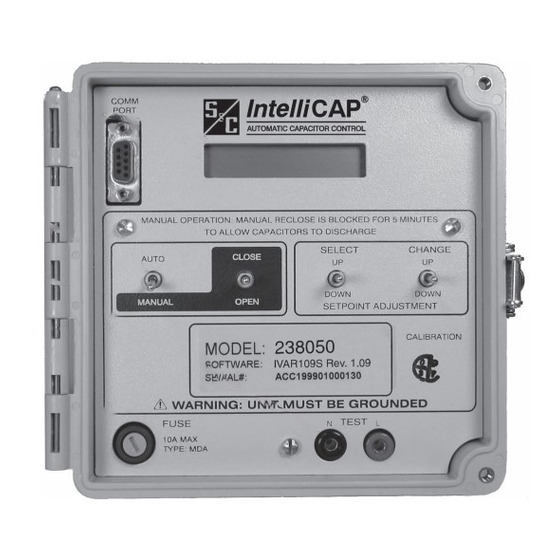
Local comm port Switches Test points 10-A load fuse Figure 1. The IntelliCap Control faceplate. Faceplate Features AUTO/MANUAL switch—Toggle this switch up to enable Automatic control operation and block commands from the faceplate CLOSE/OPEN switch. Toggle this switch down to disable Automatic operation. -
Page 7: Control Software
Closed/open status of the capacitor bank [Evnt] Active event; if no event is active, the display reads **None/Unit OK** [OperMode] The present operating mode of the IntelliCAP (hardware manual, software manual, or automatic) [AUTO] The automatic control strategy for the present season... -
Page 8: Setup Software
• Downloading new control software into the IntelliCap control • Troubleshooting installation problems The IntelliCap control reports voltage, current, and phase-related data in units of volts, amps, kvars, kW, and kVA. The rated accuracy of these measurements (±0.3% of full scale) is based on the combined accuracy of all control components, exclusive of the sensor and sensor cable, but including all sensor conditioning components. -
Page 9: Intellicap Control Operation
The control automatically switches the bank using a variety of control strategies: Temperature, Timeclock, Voltage Only, Time-Biased Voltage, Time-Biased Temperature, Automatic Online, or Automatic Offline. The IntelliCap with Var control has two additional control strategies: Current and Var. The control switches the bank based on a prioritized set of conditions. From highest to lowest priority, these are: Five-minute reclose delay—After opening the bank, the control will not close it for... - Page 10 IntelliCap Control Operation Timeclock Control Mode When Automatic mode is enabled and the control is configured for Timeclock mode, the control switches the bank based on a time schedule. Two different time schedules can be configured, and the control uses the following logic to determine when to switch the bank: (a) The control checks to see whether the present time is in one of the scheduled On periods.
- Page 11 IntelliCap Control Operation (c) If voltage remains continuously above the High-Voltage Override setpoint for the duration of the Over-Voltage Override-Time timer, the control switches the bank out. If voltage remains continuously below the Low-Voltage Override setpoint for the duration of the Under-Voltage Override-Time timer, the control switches the bank in.
- Page 12 IntelliCap Control Operation Figure 4. Voltage control switching with the preferred-bank position in Offline mode. Time-Biased Temperature Control Mode When Automatic operation is enabled and the control is in Time-Biased Temperature mode, the control switches the bank based on two sets of temperature setpoints. Time- Biased Temperature mode uses the same logic as Temperature mode, except: •...
- Page 13 Current Sensor Location and Reverse Current Flow For the IntelliCap with Var control, the preferred location of the current sensor is on the source side of the capacitor bank. The sensor can then measure the effect of the bank when it is online.
- Page 14 IntelliCap Control Operation Figure 5. Current sensor location and the direction of current flow combinations. Figure 5 shows the four possible current-sensor locations and direction of current flow. The operating conditions are described for current-flow direction: A. Sensor on Normal Source Side with Normal Current Flow The kvar level measured at the sensor location shows the effect of the bank.
-
Page 15: Viewing Data Logging
High-Low button on the Data Logging Menu screen. See Figure 6. Screens can be selected to show historical information for each day of the last month. Figure 7 shows the menu for the IntelliCap with Var control. The menu for the standard IntelliCap control only contains data for the options it supports. -
Page 16: Sensor Profiles
Viewing Data Logging Daily High and Low Data The Daily High and Low screens show the highest and lowest values for voltage, temperature, current, power factor, kvar, or kW for a 24-hour period (12 midnight to 12 midnight). The high/low data for today and for each of the preceding 31 days is available. To display a Daily High and Low screen, click on the Data Logging button. - Page 17 If the correct location for the present sample is after the end of the log, the process is the same as for a new data logging interval. When an IntelliCap control is returned from the field, generate all necessary reports as soon as possible. This minimizes the amount of lost data.
-
Page 18: Switching Level Data
Estimated Value setpoint on the Setup>General screen. When the Bank Voltage Change + Margin: Automatic Calculation mode is enabled, the control uses the delta values shown on this screen in the calculation. See Setup Instructions 1022-530, “S&C IntelliCap ® Automatic Capacitor Control: Setup” for more details. -
Page 19: Event Logs
Viewing Data Logging View the kvar Levels During Switching For the IntelliCap with Var control, every time the bank switches in or out (manually or automatically), the control records the kvar levels before and after switching. These values are shown on the Data Logging: kvar Levels During Switching screen. -
Page 20: Data Graphing
Viewing Data Logging Date and Time This is the date and time when the switching operation occurred. Request Type This is the type of request (manual, voltage override, etc.) that caused the bank to switch. View the Power Outages Log The Data Logging: Power Outages screen shows the date and time of the last 15 power cycles. - Page 21 Viewing Data Logging The amount of data in the sensor profile graphs depends on the configured data logging interval. See the “View the Sensor Profile Screens” section on page 16 for more details. Follow these steps to display sensor profiles: Click on the Data Graphing button.
-
Page 22: Generating Reports
Generating Reports The IntelliCap control report feature will transfer most of the control settings and stored data to a PC as a CSV (comma-separated value) file. The report can be stored as a permanent record and used in spreadsheets or other program types. Follow these steps to generate a report: Connect a PC to the IntelliCap control and start the IntelliLink software. -
Page 23: Saving And Logging A Setup Configuration
Saving and Loading a Setup Configuration When several IntelliCap controls use a similar setup configuration, the configuration from one control can be saved and loaded into other controls. Only the setpoints that are different for each control need to be configured. -
Page 24: Using Virtual Memory Files
IntelliCap control. To access the information, connect to the file stored on the computer instead of the physical control. -
Page 25: Updating Control Software
. When you must cancel the process, the update process must be started again . Note: If the software to be loaded is not the same type as the software in the IntelliCap control, an error message is displayed. Note which software version is already in the control. -
Page 26: Running Setup Software From Dos
(for example, CD C:\ELINE) are stored, and press the <Enter> key. STEP 2. Type ACAP, and press the <Enter> key. Follow these steps to start the setup software for the IntelliCap control from the subdirectory with the IntelliCap files on the computer: STEP 1.
Need help?
Do you have a question about the IntelliCap and is the answer not in the manual?
Questions and answers