
Related Manuals for ADLINK Technology EPS Series


Summary of Contents for ADLINK Technology EPS Series
- Page 1 EPS Series EtherCAT Slave System User’s Manual 2.00 Manual Rev.: Aug. 2, 2015 Revision Date: 50-17043-1000 Part No: Advance Technologies; Automate the World.
- Page 2 Revision History Revision Release Date Description of Change(s) 2.00 2015/10/2 Initial Release...
-
Page 3: Preface
EPS Series Preface Copyright 2015 ADLINK TECHNOLOGY, INC. This document contains proprietary information protected by copy- right. All rights are reserved. No part of this manual may be repro- duced by any mechanical, electronic, or other means in any form without prior written permission of the manufacturer. - Page 4 ® ® ® 98, Windows NT, Windows 2000, Windows XP, and ® ® ® Windows Vista are registered trademarks of Microsoft Corporation. PCI™, is a registered trademark of the Peripheral Component Interconnect Special Interest Group (PCI-SIG). Product names mentioned herein are used for identification pur- poses only and may be trademarks and/or registered trademarks of their respective companies.
-
Page 5: Table Of Contents
EPS Series Table of Contents Preface ..................iii List of Figures ................ ix List of Tables................xi 1 Introduction ................ 1 Features................2 Specifications............... 3 1.2.1 EPS-9905 Chassis ............. 3 1.2.2 EPS-1132 Module ............4 1.2.3 EPS-2032 Module ............4 1.2.4... - Page 6 3 EPS System Modules ............19 EPS-1132 ................20 3.1.1 Connector and Wiring ..........22 3.1.2 LED Indicators ............23 3.1.3 Signal Connection............. 23 3.1.4 Object Dictionary ............24 EPS-2032 ................24 3.2.1 Connector and Wiring ..........26 3.2.2 LED Indicators ............27 3.2.3 Signal Connection.............
- Page 7 EPS Series 3.7.2 LED Indicators ............50 3.7.3 Signal Connection ............ 50 3.7.4 Object Dictionary ............51 EPS-4008 ................51 3.8.1 Connector and Wiring..........54 3.8.2 LED Indicators ............55 3.8.3 Signal Connection ............ 55 3.8.4 Object Dictionary ............56 EPS-6000 ................
- Page 8 Important Safety Instructions..........101 Getting Service ..............103 viii Table of Contents...
-
Page 9: List Of Figures
EPS Series List of Figures Figure 1-1: Front View (slots vacant) .......... 10 Figure 1-2: Front View (EPS-6000 EtherCAT bus coupler module installed) 11 Figure 1-3: (Left) Side View ............12 Figure 1-4: Top View..............13 Figure 1-5: EPS System w/ Modules Installed......14 Figure 3-1: EPS-1132 Specifications .......... - Page 10 This page intentionally left blank. List of Figures...
-
Page 11: List Of Tables
EPS Series List of Tables Table 3-1: EPS Peripheral Modules..........19 Table 3-2: EPS-1132 Pin Assignment ..........21 Table 3-3: LED Indicator Legend ............ 23 Table 3-4: EPS-2032 Specifications ..........24 Table 3-5: EPS-2032 Pin Assignment ..........25 Table 3-6: LED Indicator Legend ............ 27 Table 3-7: EPS-2132 Specifications .......... - Page 12 This page intentionally left blank. List of Tables...
- Page 13 EPS Series Introduction The ADLINK complete EtherCAT solution, from hardware to mid- dleware to software, with every element tailored for dedicated EtherCAT functionality, includes Talos master controllers, EPS slave systems, and remote monitoring and control providers. As well, ADLINK’s Softmotion one-stop control kernel delivers flexible and easy-to-use intelligent platforms for driving next-generation modern Smart Factories.
-
Page 14: Introduction
1.1 Features Compatible with certified 3rd party EtherCAT masters Comprehensive slave modules include high-density digital I/ O, analog I/O, thermal measurement, and motion control EtherCAT COE, FOE protocol support Compliance with industrial IEC standard Automatic Detection System by LinkMasterPro™ applica- tion detects and generates corresponding ESI files automat- ically Intelligent status monitoring for EPS modules... -
Page 15: 1.2 Specifications
EPS Series 1.2 Specifications 1.2.1 EPS-9905 Chassis System Level Processor Xillinx Zynq SoC 512 MB DDR3 Retain 16MB Flash on Bus Coupler Memory Memory #1 Retain 128KB FRAM on every EPS Memory #2 module Connectivity EtherCAT 2 EtherCAT ports Motion Protocol... -
Page 16: Eps-9905 Chassis
EN 60068-2-6 certification Vibration Operating, 5 Grms, 5-500 Hz, 3 axes Contact +/-4 kV and Air +/-8 kV EN 60068-2-27 certification Shock Operating, 100 G , half sine 11 ms duration (w/ mSATA) EN 61000-2 / EN 61000-4 certification CE and FCC Class A Safety UL, CB 1.2.2... -
Page 17: Eps-1132 Module
EPS Series 300mA per CH Output Current (Iout) 800mA per 4-CH Output Voltage (Vout) EVCC – (Iout x Rout) IO Protection Reverse Voltage None IO Protection Current limit 1.2A for 4CH IO Protection Short Circuit None Power On State Response Time... -
Page 18: Eps-2132 Module
1.2.5 EPS-2308 Module Channels Type SPST (Single pole single throw) Maximum switched voltage and 30V/2A, 240V/0.5A current Output Impedance (Rout) 50mΩ (Typ.) IO Protection Reverse Voltage Power On State Response Time Operate 10ms & release 5ms (Typ.) Power Consumption from Chassis <... -
Page 19: Eps-2308 Module
EPS Series < 2.55W (max.) @ Thermal Dissipation (at max temp.) EVCC=24V+10% Operating Temperature -20 to 60°C Isolation (Channel-to-DGND) 2kV (DC) Isolation (Channel-to-Chassis) 2kV (DC) 1.2.7 EPS-3216 Module Channels 16 Single-ended Input Range 0-20mA Resolution 16 bit Offset Error 0.5μA Offset Drift 0.0005% of range per °C... -
Page 20: Eps-3216 Module
Accuracy (DC) ± 0.007% of FSR Accuracy (Temperature) ± 0.5°C Excitation Current (Max.) 500μA Power Consumption from Chassis < 450mW (max.) Thermal Dissipation (at max < 2.55W (max.) @ temp.) EVCC=24V+10% Operating Temperature -20 to 60°C Isolation (Channel-to-DGND) 2kV (DC) Isolation (Channel-to-Chassis) 2kV (DC) 1.2.9... -
Page 21: Eps-4008 Module
EPS Series 1.2.10 EPS-6000 Module EPS Module Support (slots) 4 (Max.) Field Bus Connectivity EtherCAT Data Transmission Rate 100 Mbaud Bus Interface 2 x RJ45 Cable for EtherCAT Connectivity CAT5 / CAT5e (recommended) Inner Bus Synchronization > 0.1µs Supply Voltage 24VDC (±... - Page 22 Isolation (Channel-to-Chassis) 2kV (DC) Introduction...
-
Page 23: 1.3 Schematics
EPS Series 1.3 Schematics All dimensions are shown in mm (millimeters) NOTE: NOTE: Figure 1-1: Front View (slots vacant) Introduction... -
Page 24: Figure 1-2: Front View
Figure 1-2: Front View (EPS-6000 EtherCAT bus coupler module installed) Introduction... -
Page 25: Figure 1-3: (Left) Side View
EPS Series 123.5 Figure 1-3: (Left) Side View Introduction... -
Page 26: 1.4 Eps Slave System Composition
Figure 1-4: Top View 1.4 EPS Slave System Composition Each EPS slave system provides 5 slots total, with the far left reserved for bus coupler installation. The remaining slots flexibly support a variety of EPS slave modules. For individual module details, please see Chapter 3: EPS System Modules. -
Page 27: Figure 1-5: Eps System W/ Modules Installed
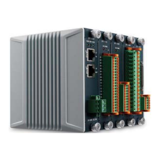
EPS Series Various Modules Installed Bus Coupler Installed Figure 1-5: EPS System w/ Modules Installed Introduction... -
Page 28: Getting Started
EPS Series Getting Started As mentioned previously, each EPS slave system can support up to 4 peripheral modules, installed to support the application. Sup- ported EPS peripheral modules are as follows, and provide digital input, digital output, relay output, analog input, analog output, and thermal input with RTD sensor support, as well as pulse-train motion modules. -
Page 29: 2.2 Cooling Considerations
2.2 Cooling Considerations Heat generated by the EPS system is conducted to the chassis on both sides. To maximize heat dissipation, maintain a minimum 2 inches (5 cm) clearance on the top of the EPS-9905 & 1 inch on either side.. Internal thermal status is monitored by onboard thermal sen- sors and reported to the Host automatically to ensure prompt action in the event of temperature overages. -
Page 30: 2.3 Hardware Installation
2.3 Hardware Installation 2.3.1 Installing the Bus Coupler Module The EPS Series incorporates a system controller slot supporting a PXI Express system controller of up to 4 slot width. 1. Align the module with the slot guide in the chassis and carefully slide the module into the slot until seated. -
Page 31: 2.4 Rack Mounting
To improve efficiency of heat dissipation, install filler plates for any unused slots. NOTE: NOTE: 2.4 Rack Mounting The EPS slave system is shipped with DIN rail mounting brackets and accessory screws pre-installed. If the installation appears incomplete, contact ADLINK technical support. 1. -
Page 32: Eps System Modules
The EPS Series provides software configurable trigger bus bridges, whereby the user can set the status of each trigger bus line. The EPS Series backplane can also be configured between 4-link x 4 lanes or 2-link x 8 lanes by the configurable PCIe switch fabric. -
Page 33: Eps-1132
Unregistered EPS peripheral modules cannot be installed in slots configured and registered to a different EPS peripheral module type. EPS modules can only be swapped out for CAUTION: another of the same type, or the new module must be regis- tered and the ESI file regenerated, to reconfigure the entire EtherCAT system. -
Page 34: Table 3-2: Eps-1132 Pin Assignment
EPS Series DI00 DI01 DI02 DI03 DI04 DI05 DI06 DI07 EGND EGND DI08 DI09 DI10 DI11 DI12 DI13 DI14 DI15 EGND EGND DI16 DI17 DI18 DI19 DI20 DI21 DI22 345 DI23 EGND EGND DI24 DI25 DI26 DI27 DI28 DI29 DI30... -
Page 35: Connector And Wiring
Figure 3-2: EPS-1132 Schematic 3.1.1 Connector and Wiring Connector: Phoenix Contact, DFMC series, 1787195 Pitch=3.5mm 2x20pin AWG 16-24 gauge EPS System Modules... -
Page 36: Led Indicators
EPS Series 3.1.2 LED Indicators Action Status Over temperature protection Blinking Module present Module power status Channel (0-3, 4-7, 8-11, 12-15, 16-19, Channel active 20-23, 24-27, 28-31) Table 3-3: LED Indicator Legend 3.1.3 Signal Connection Sourcing-Output Device Dixx External Power... -
Page 37: Object Dictionary
3.1.4 Object Dictionary 0x3000 Index Type Read digital input 32 bit Name Digital input channels 1 to 32 Description 3.2 EPS-2032 The EPS-2032 high density 32CH sinking type digital output mod- ule operates in environments from -20°C to 60°C and provides high isolation protection and hot-swappability. -
Page 38: Table 3-5: Eps-2032 Pin Assignment
EPS Series EVCC EVCC CH00 CH01 CH02 CH03 CH04 CH05 CH06 CH07 CH08 CH09 CH10 CH11 CH12 CH13 CH14 CH15 EGND EGND EVCC EVCC CH16 CH17 CH18 CH19 CH20 345 CH21 CH22 CH23 CH24 CH25 CH26 CH27 CH28 CH29 CH30... -
Page 39: Connector And Wiring
Figure 3-3: EPS-2032 Schematic 3.2.1 Connector and Wiring Connector: Phoenix Contact, DFMC series, 1787195 Pitch=3.5mm 2x20pin AWG 16-24 gauge EPS System Modules... -
Page 40: Led Indicators
EPS Series 3.2.2 LED Indicators Action Status Over temperature protection Blinking Module present Module power status Channel (0-3, 4-7, 8-11, 12-15, 16-19, Channel active 20-23, 24-27, 28-31) Table 3-6: LED Indicator Legend 3.2.3 Signal Connection EVCC Device DOxx External Power... -
Page 41: Eps-2132
Write digital input 32 bit Name Digital input channels 1 to 32 Description 3.3 EPS-2132 The EPS-2132 high density 32CH sourcing type digital output module operates in environments from -20°C to 60°C and pro- vides high isolation protection and hot-swappability. Channels Sinking Output Type... -
Page 42: Table 3-8: Eps-2132 Pin Assignment
EPS Series EGND EGND CH00 CH01 CH02 CH03 CH04 CH05 CH06 CH07 CH08 CH09 CH10 CH11 CH12 CH13 CH14 CH15 EVCC EVCC EGND EGND CH16 CH17 CH18 CH19 CH20 345 CH21 CH22 CH23 CH24 CH25 CH26 CH27 CH28 CH29 CH30... -
Page 43: Connector And Wiring
Figure 3-4: EPS-2132 Schematic 3.3.1 Connector and Wiring Connector: Phoenix Contact, DFMC series, 1787195 Pitch=3.5mm 2x20pin AWG 16-24 gauge EPS System Modules... -
Page 44: Led Indicators
EPS Series 3.3.2 LED Indicators Action Status Over temperature protection Blinking Module present Module power status Channel (0-3, 4-7, 8-11, 12-15, 16-19, Channel active 20-23, 24-27, 28-31) Table 3-9: LED Indicator Legend 3.3.3 Signal Connection EVCC Device DOxx External Power... -
Page 45: Eps-2308
Write digital output 32 bit Name Digital output channels 1 to 32 Description 3.4 EPS-2308 The EPS-2308 8CH SPST relay output module operates in envi- ronments from -20°C to 60°C and provides high isolation protec- tion and hot-swappability. Channels SPST (single pole single throw) Output Type Maximum switched voltage and 30V/2A, 240V/0.5A... -
Page 46: Table 3-11: Eps-2308 Pin Assignment
EPS Series RO0a RO0b RO1a RO1b RO2a RO2b RO3a RO3b RO4a RO4b RO5a RO5b RO6a RO6b RO7a RO7b Table 3-11: EPS-2308 Pin Assignment EPS System Modules... -
Page 47: Connector And Wiring
Figure 3-5: EPS-2308 Schematic 3.4.1 Connector and Wiring Connector: Weidmuller, OMNIMATE Signal series BL/SL 5.08, 10145300000 Pitch= 5.08mm 1x16 pin AWG 12-26 gauge EPS System Modules... -
Page 48: Signal Connection
EPS Series 3.4.2 Signal Connection ROxa ROxb Device 3.4.3 Object Dictionary 0x4000 Index Type Write RO data Name RO Output Bits 0 to 7, Bits 8 to Description 31 are reserved EPS System Modules... -
Page 49: Eps-3032
3.5 EPS-3032 The EPS-3032 high density 32CH ±10V @ 16-bit, analog input module operates in environments from -20°C to 60°C and pro- vides high isolation protection and hot-swappability. 32 single-ended Channels 16 differential ±10V Input Range 16 bit Resolution ±1mV Offset Error 0.0004% of range per °C Offset Drift... -
Page 50: Table 3-13: Eps-3032 Pin Assignment
EPS Series AI00 AI16 AI01 AI17 AI02 AI18 AI03 AI19 AI04 AI20 AI05 AI21 AI06 AI22 AI07 AI23 AGND 30 AGND AI08 AI24 AI09 AI25 AI10 AI26 AI11 345 AI27 AI12 AI28 AI13 AI29 AI14 AI30 AI15 AI31 AISE AGND... -
Page 51: Connector And Wiring
Figure 3-6: EPS-3032 Schematic 3.5.1 Connector and Wiring Connector: Phoenix Contact, DFMC series, 1787195 Pitch=3.5mm 2x20pin AWG 16-24 gauge EPS System Modules... -
Page 52: Led Indicators
EPS Series 3.5.2 LED Indicators Action Status Over temperature protection Blinking Module present Module power status Table 3-14: LED Indicator Legend 3.5.3 Signal Connection A100 A131 AISE AGND 3.5.4 Object Dictionary Index Sub Type RW Name Description 0x3000 0 Read Analog Input 16 Bit... - Page 53 Index Sub Type RW Name Description Analog Input Read Analog Input 16 Bit Channel 1 Analog Input Read Analog Input 16 Bit Channel 2 Analog Input Read Analog Input 16 Bit Channel 3 Analog Input Read Analog Input 16 Bit Channel 4 Analog Input Read Analog Input 16 Bit...
- Page 54 EPS Series Index Sub Type RW Name Description Analog Input Read Analog Input 16 Bit Channel 19 Analog Input Read Analog Input 16 Bit Channel 20 Analog Input Read Analog Input 16 Bit Channel 21 Analog Input Read Analog Input 16 Bit...
-
Page 55: Eps-3216
3.6 EPS-3216 The EPS-3216 high density 16CH 0-20mA @ 16-bit, analog input module operates in environments from -20°C to 60°C and pro- vides high isolation protection and hot-swappability. 16 single-ended Channels 0-20mA Input Range 16 bit Resolution 0.5μA Offset Error 0.0005% of range per °C Offset Drift ±0.05% of FSR... -
Page 56: Table 3-16: Eps-3216 Pin Assignment
EPS Series AI00 AI01 AI02 AI03 AI04 AI05 AI06 AI07 AGND 30 AGND AI08 AI09 AI10 AI11 345 N/C AI12 AI13 AI14 AI15 AGND AGND Table 3-16: EPS-3216 Pin Assignment EPS System Modules... -
Page 57: Connector And Wiring
Figure 3-7: EPS-3216 Schematic 3.6.1 Connector and Wiring Connector: Phoenix Contact, DFMC series, 1787195 Pitch=3.5mm 2x20pin AWG 16-24 gauge EPS System Modules... -
Page 58: Led Indicators
EPS Series 3.6.2 LED Indicators Action Status Over temperature protection Blinking Module present Module power status Table 3-17: LED Indicator Legend 3.6.3 Signal Connection Sourcing-Output Device Dixx External Power Supply EGND EPS System Modules... -
Page 59: Object Dictionary
3.6.4 Object Dictionary Index Sub Type RW Name Description 0x3000 0 Read Analog Input 16 Bit Analog Input Read Analog Input 16 Bit Channel 0 Analog Input Read Analog Input 16 Bit Channel 1 Analog Input Read Analog Input 16 Bit Channel 2 Analog Input Read Analog Input 16 Bit... -
Page 60: Eps-3504
EPS Series 3.7 EPS-3504 The EPS-3504 4CH 24-bit, RTD thermal input module supports PT100, PT500 and PT1000 sensors, operates in environments from -20°C to 60°C, and provides high isolation protection and hot- swappability. 4 RTD Channels PT100, PT500, PT1000 Sensor Type... -
Page 61: Table 3-19: Eps-3504 Pin Assignment
AGND EX0+ SI0+ EX1+ SI1+ EX2+ SI2+ EX3+ SI3+ AGND AGND EX0- SI0- EX1+ SI1+ EX2+ SI2+ EX3+ SI3+ AGND Table 3-19: EPS-3504 Pin Assignment EPS System Modules... -
Page 62: Connector And Wiring
EPS Series Figure 3-8: EPS-3504 Schematic 3.7.1 Connector and Wiring Connector: Phoenix Contact, DFMC series, 1787195 Pitch=3.5mm 1x20pin AWG 16-24 gauge EPS System Modules... -
Page 63: Led Indicators
3.7.2 LED Indicators Action Status Over temperature protection Blinking Module present Module power status Table 3-20: LED Indicator Legend 3.7.3 Signal Connection EXx+ SIx+ 24-bit SIx- EXx- EPS System Modules... -
Page 64: Object Dictionary
EPS Series 3.7.4 Object Dictionary Index Sub Type RW Name Description 0x3000 0 RTD Data Channel 0 Ch-0 Data Channel 1 Ch-1 Data Channel 2 Ch-2 Data Channel 3 Ch-3 Data 3.8 EPS-4008 The EPS-4008 8CH ±10V @ 16-bit, analog output module oper- ates in environments from -20°C to 60°C, and provides high isola-... -
Page 65: Table 3-21: Eps-4008 Specifications
8CH Single-ended Channels ±10V Output Range 16 bit Resolution 100kHz Sampling Rate ± 0.2mV Offset Error ± 0.05% of FSR Gain Error ± 0.0075mV /°C Offset Drift ± 0.00025% /°C of FSR Gain Drift 5 mA Output Current Capacity Relay off Power On State ±... -
Page 66: Table 3-22: Eps-4008 Pin Assignment
EPS Series AO01 AO02 AO03 AO04 AO05 AO06 AO07 AO08 AGND AGND AGND AGND AGND AGND AGND AGND Table 3-22: EPS-4008 Pin Assignment EPS System Modules... -
Page 67: Connector And Wiring
Figure 3-9: EPS-4008 Schematic 3.8.1 Connector and Wiring Connector: Phoenix Contact, DFMC series, 1787195 Pitch=3.5mm 1x20pin AWG 16-24 gauge EPS System Modules... -
Page 68: Led Indicators
EPS Series 3.8.2 LED Indicators Action Status Over temperature protection Blinking Module present Module power status Table 3-23: LED Indicator Legend 3.8.3 Signal Connection AO[0:7] 16-bit AGND EPS System Modules... -
Page 69: Object Dictionary
3.8.4 Object Dictionary Index Sub Type RW Name Description 0x3000 0 RW Write Analog Output 16 Bit Analog Output RW Write Analog Output 16 Bit Channel 0 Analog Output RW Write Analog Output 16 Bit Channel 1 Analog Output RW Write Analog Output 16 Bit Channel 2 Analog Output RW Write Analog Output 16 Bit... -
Page 70: Table 3-24: Eps-6000 Specifications
EPS Series Up to 4 (slots) EPS Module Support Ethernet Connectivity EtherCAT Field Bus Connectivity 100 Mbaud Data Transmission Rate 2 x RJ45 Bus Interface Cable for EtherCAT Connection CAT5 / CAT5e (recommended) > 0.1µs Inner Bus Synchronization 24V DC (± 10%) - Page 71 X1 & X2 Description Termination Termination Termination Termination EPS System Modules...
-
Page 72: Table 3-25: Eps-6000 Pin Assignment
EPS Series Description Power Description External Ground Shielding Ground External Power Input Table 3-25: EPS-6000 Pin Assignment EPS System Modules... -
Page 73: Connector And Wiring
Figure 3-10: EPS-6000 Schematic 3.9.1 Connector and Wiring Connector: Phoenix Contact, DFMC series, 1787195, pitch=3.5mm, 2x5 pin, AWG 16-24 gauge SCSI VHDCI 68p: Y cable accessory (for servo connection) EPS System Modules... -
Page 74: Led Indicators
EPS Series 3.9.2 LED Indicators Display Function Description Power ON System Power Status Power OFF / Power level below 20V Error System Error Blinking Warning (XXXX for details) Handling No warning and error Normal operation EtherCAT No power Communication Under configuration... -
Page 75: Object Dictionary
3.9.3 Object Dictionary Index Type Name Description Write Analog Output 0x4000 16 Bit Write Analog Output Analog Output 16 Bit Channel 0 Write Analog Output Analog Output 16 Bit Channel 1 Write Analog Output Analog Output 16 Bit Channel 2 Write Analog Output Analog Output 16 Bit... -
Page 76: Table 3-27: Eps-7002 Specifications
EPS Series Channels 4MHz Output Frequency CW/CCW, OUT/DIR Output Modes Encoder Input Channels 20MHz @ 4xAB Encoder Input Frequency CW/CCW, 1x/2x/4x AB Phase Encoder Input Modes TTL, Incremental Encoder Input Type PEL, MEL, ORG Motion I/O Interface ALM, INP, RDY, SVON, ERC, RST... - Page 77 Motion I/O Description MEL1 PEL2 MEL2 PEL1 ORG1 ORG2 EPS System Modules...
-
Page 78: Table 3-28: Eps-7002 Pin Assignment
EPS Series D-SUB26P Name Function SVON Servo On signal In-position signal Dev ctr, clr. Signal servo ready signal OUT- Pulse signal (-) OUT+ Pulse signal (+) Encoder A-phase(-) Encoder A-phase(+) Reserved Reset driver signal Servo alarm signal Ext. power supply, +24V Ext. -
Page 79: Figure 3-11: Eps-7002 Schematic
It is recommended to connect signal to specific servo drives with dedicated cables. Docking connector is DSUB-26p. NOTE: NOTE: Figure 3-11: EPS-7002 Schematic EPS System Modules... -
Page 80: Led Indicators
EPS Series 3.10.1 LED Indicators Status Function Emergency Stop Input Over Temperature Protection Blinking Module Present Module Power Status Table 3-29: LED Indicator Legend 3.10.2 Signal Connection OUT+, DIR+ OUT-, DIR- SVON, RST, ERC, EMG_OUT FPGA PEL, MEL, ORG, ALM,... - Page 81 Index Type Name 0x60BA Touch Probe 0 Positive Edge Value 0x60BB Touch Probe 1 Positive Edge Value 0x60BC Touch Probe 0 Negative Edge Value 0x60BD Touch Probe 1 Negative Edge Value 0x60FD Axis 0 Motion Output 0x60FE Axis 0 Motion Input 0x6840 Control Word 0x6841...
-
Page 82: A Appendix: Linkmasterpro
EPS Series Appendix A - LinkMasterPro™ LinkMasterPro™, ADLINK's EtherCAT utility, enables configura- tion of EPS slave systems and generation of corresponding ESI files for EtherCAT master controllers. LinkMasterPro™ further provides intuitive I/O control dialogues to assess the integrity of each EPS peripheral module's wiring. -
Page 83: Figure A-1: Linkmasterpro™ Operational Overview
LinkMasterPro.exe application tool Export ESI file & Scan bus coupler update to to detect slaves EEPROM EtherCAT Update binary file or Get OD Figure A-1: LinkMasterPro™ Operational Overview LinkMasterPro™... -
Page 84: A.1 Interface
EPS Series A.1 Interface Figure A-2: LinkMasterPro™ Interface MAC Address Selection Scan for Devices Button Export ESI (*.xml) Button Tree View Window Device Window Object Dictionary Window Message Window Table A-1: LinkMasterPro™ Interface Legend LinkMasterPro™... -
Page 85: A.2 Installation
A.2 Installation Install the LinkMasterPro_v1.0.exe SDK to the suggested path C:\Program Files\ADLINK\LinkMasterPro Click Next and Install through until installation is complete. LinkMasterPro™... - Page 86 EPS Series Once installation is complete, the application can be launched by following Start>All Programs>ADLINK>LinkMasterPro or by going to C:\Program Files\ADLINK\LinkMasterPro and executing Link- MasterPro.exe. LinkMasterPro™...
-
Page 87: A.3 Controls And Function
Figure A-3: LinkMasterPro™ Folder A.3 Controls and Function A.3.1 Selecting MAC Address To begin with LinkMasterPro™, the physical MAC address on the master must be entered, or hte application is unable to scan the EtherCAT device properly. If the incorrect MAC is entered, an error message appears as shown. -
Page 88: Scanning For Devices
EPS Series Figure A-4: Scan Failure Notification Before operating any controls, ensure all slave modules are properly connected and no other fieldbus devices or applica- tions are in use. CAUTION: A.3.2 Scanning for Devices When the Scan for Devices button is activated, the EPS slave sys- tem is displayed in the device tree view as shown. -
Page 89: Exporting Esi
Figure A-5: EPS Slave System in Tree View A.3.3 Exporting ESI When the Export ESI button is activated, the ESI file (*.xml) is saved to disk and the EPS system simultaneously, with the Save path selected as shown. LinkMasterPro™... -
Page 90: Figure A-6: Save Esi Path Selection
EPS Series Figure A-6: Save ESI Path Selection The ESI (EtherCAT slave information) file includes product code, vendor ID, TxPDO/RxPDO, and other slave data. It recognizes peripheral module types and locates memory space required to control the I/O on the EPS peripheral modules thru EtherCAT. -
Page 91: Figure A-7: Esi Export Progress Display
Figure A-7: ESI Export Progress Display The action also programs the content to EEPROM on the individ- ual EPS slave system. When ESI generation is complete a notifi- cation appears as shown. LinkMasterPro™... -
Page 92: Device Tree View
EPS Series Figure A-8: Export Successful Display The ESI file can further be used for CoDeSys, configuring Ether- CAT for integration into the IEC 61131-3 Development System. To save time, LinkMasterPro automatically copies the ESI file of EPS system to the specific CoDeSys path, named device.xml. -
Page 93: Figure A-9: Eps Slave System Panel
Corresponding EPS module dialogue appears when the specific slave system is selected. Figure A-9: EPS Slave System Panel LinkMasterPro™... -
Page 94: Table A-2: Eps Slave System Panel Operations
EPS Series Item Function Switching tab panel displays Module Tab Panel individual module information I/O Panel Opens I/O display FOE (File Over Transfers files over EtherCAT EtherCAT) Button (write *.bin file over EtherCAT) Displays OD info <index: value> OD Info Button... -
Page 95: Figure A-10: Eps-6000 Product Page (Default Slot 1 Installation)
Figure A-10: EPS-6000 Product Page (default Slot 1 installation) Generally, individual EPS module pages display the module type, module identification, HW version, SW version, and ADLINK serial number, as well as error code. The page for the EPS-2032 module (installed here in Slot 2) is shown as an example. LinkMasterPro™... -
Page 96: Figure A-11: Eps-2032 Product Page (Exemplary Slot 2 Installation)
EPS Series Figure A-11: EPS-2032 Product Page (exemplary Slot 2 installation) To optimize data transmission between the EtherCAT master and EPS slave system, time offset can be adjusted via the Distribute Clock (DC) tab, as shown. LinkMasterPro™... -
Page 97: Figure A-12: Dc Dialog Page
Figure A-12: DC Dialog Page LinkMasterPro™... -
Page 98: Error Logging And History
EPS Series Figure A-13: DC Parameters Page A.3.5 Error Logging and History Error logging provides error history saved in the EPS-6000's onboard flash memory. Capacity in the memory is 256 error codes. Refresh displays the error data and corresponding descrip- tion in the Information Panel (right side) when each value is selected. -
Page 99: Foe (File Over Ethercat)
Figure A-14: Error Log Page (w/ Index 0 selected) A.3.6 FOE (File Over EtherCAT) Slave functions can be reprogrammed dynamically by updating slave code (*bin). The FOE button opens the binary file listing and enables download to the EEPROM of the EPS slave system. Ensure that no other LinkMasterPro™... -
Page 100: Figure A-15: Binary File Selection
EPS Series Figure A-15: Binary File Selection When the procedure is complete, a notification appears, as shown. LinkMasterPro™... -
Page 101: Getting Od Info
Figure A-16: Binary File Download Success Notification Restart the EPS system to activate the functions. If the procedure fails,the slave code may need to be downloaded again. If failure persists, please contact ADLINK technical support. A.3.7 Getting OD Info The Get OD button displays values corresponding to each index/ sub-index in the table for review. -
Page 102: Module I/O Panels
EPS Series Figure A-17: OD List A.3.8 Module I/O Panels Selecting a module in the Device Window opens the I/O panel for that module. LinkMasterPro™... -
Page 103: Figure A-18: Module Selection
Figure A-18: Module Selection Each module's I/O panel displays its I/O information, as shown. LinkMasterPro™... - Page 104 EPS Series EPS-2032 Indicator represents 1 bit, clicking allows status to be changed. LinkMasterPro™...
- Page 105 EPS-2132 Indicator represents 1 bit, clicking allows status to be changed. LinkMasterPro™...
- Page 106 EPS Series EPS-1132 Indicator represents 1 bit, and is read-only. LinkMasterPro™...
- Page 107 EPS-4008 Enables voltage to be changed, with current value displayed on the right. Apply implements changes, and Reset rolls values back to 0. LinkMasterPro™...
- Page 108 EPS Series EPS-3032 Displays voltage data, and is read-only. LinkMasterPro™...
- Page 109 EPS-3216 Displays current data, and is read-only. LinkMasterPro™...
- Page 110 EPS Series EPS-2308 Enables status to be switched on and off. LinkMasterPro™...
- Page 111 EPS-3504 Displays channel data in ohms (Ω). LinkMasterPro™...
- Page 112 EPS Series EPS-7002 Displays Softmotion encoder data and status. 3rd party EtherCAT devices installed in the same line merely show vendor ID in the tree view. LinkMasterPro™...
-
Page 113: Exporting Log Messages
A.3.9 Exporting Log Messages All currently displayed messages can be exported by clicking Export Log. Log filenames follow a “Log_year-month-date_hour- min-sec.txt” format. Files are saved in the LinkMasterPro™ direc- tory. All current messages can be cleared by clicking Clear. A.3.10 Version Information LinkMasterPro™... - Page 114 EPS Series Important Safety Instructions For user safety, please read and follow all instructions, WARNINGS, CAUTIONS, and NOTES marked in this manual and on the associated equipment before handling/operating the equipment. Read these safety instructions carefully. Keep this user’s manual for future reference.
- Page 115 Never attempt to fix the equipment. Equipment should only be serviced by qualified personnel. A Lithium-type battery may be provided for uninterrupted, backup or emergency power. Risk of explosion if battery is replaced with an incorrect type; please dispose of used batteries appropriately. WARNING: Equipment must be serviced by authorized technicians when:...
- Page 116 San Jose, CA 95138, USA Tel: +1-408-360-0200 Toll Free: +1-800-966-5200 (USA only) Fax: +1-408-360-0222 Email: info@adlinktech.com ADLINK Technology (China) Co., Ltd. Address: (201203) 300 Fang Chun Rd., Zhangjiang Hi-Tech Park Pudong New Area, Shanghai, 201203 China Tel: +86-21-5132-8988 Fax: +86-21-5132-3588 Email: market@adlinktech.com...
- Page 117 84 Genting Lane #07-02A, Cityneon Design Centre Singapore 349584 Tel: +65-6844-2261 Fax: +65-6844-2263 Email: singapore@adlinktech.com ADLINK Technology Singapore Pte. Ltd. (Indian Liaison Office) Address: #50-56, First Floor, Spearhead Towers Margosa Main Road (between 16th/17th Cross) Malleswaram, Bangalore - 560 055, India Tel: +91-80-65605817, +91-80-42246107 Fax:...
- Page 118 Mouser Electronics Authorized Distributor Click to View Pricing, Inventory, Delivery & Lifecycle Information: ADLINK Technology EPS-1032...
Need help?
Do you have a question about the EPS Series and is the answer not in the manual?
Questions and answers