Sign In
Upload
Manuals
Brands
ADLINK Technology Manuals
Controller
EPS Series
ADLINK Technology EPS Series Manuals
Manuals and User Guides for ADLINK Technology EPS Series. We have
1
ADLINK Technology EPS Series manual available for free PDF download: User Manual
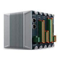
ADLINK Technology EPS Series User Manual (118 pages)
EtherCAT Slave System
Brand:
ADLINK Technology
| Category:
Controller
| Size: 6 MB
Table of Contents
Preface
3
Table of Contents
5
List of Figures
9
List of Tables
11
1 Introduction
14
1.1 Features
14
1.2 Specifications
15
EPS-9905 Chassis
16
EPS-1132 Module
17
EPS-2032 Module
17
EPS-2132 Module
18
EPS-2308 Module
19
EPS-3032 Module
19
EPS-3216 Module
20
EPS-3504 Module
20
EPS-4008 Module
21
EPS-6000 Module
21
EPS-7002 Module
21
1.3 Schematics
23
Figure 1-1: Front View (Slots Vacant)
23
Figure 1-2: Front View
24
Figure 1-3: (Left) Side View
25
1.4 EPS Slave System Composition
26
Figure 1-4: Top View
26
Figure 1-5: EPS System W/ Modules Installed
27
2 Getting Started
28
2.1 Package Contents
28
2.2 Cooling Considerations
29
2.3 Hardware Installation
30
Installing the Bus Coupler Module
30
Installing Peripheral Modules
30
2.4 Rack Mounting
31
Powering up the System
31
3 EPS System Modules
32
Table 3-1: EPS Peripheral Modules
32
Eps-1132
33
Figure 3-1: EPS-1132 Specifications
33
Table 3-2: EPS-1132 Pin Assignment
34
Connector and Wiring
35
Figure 3-2: EPS-1132 Schematic
35
LED Indicators
36
Signal Connection
36
Table 3-3: LED Indicator Legend
36
Object Dictionary
37
Eps-2032
37
Table 3-4: EPS-2032 Specifications
37
Table 3-5: EPS-2032 Pin Assignment
38
Connector and Wiring
39
Figure 3-3: EPS-2032 Schematic
39
LED Indicators
40
Object Dictionary
40
Signal Connection
40
Table 3-6: LED Indicator Legend
40
Eps-2132
41
Table 3-7: EPS-2132 Specifications
41
Table 3-8: EPS-2132 Pin Assignment
42
Connector and Wiring
43
Figure 3-4: EPS-2132 Schematic
43
LED Indicators
44
Object Dictionary
44
Signal Connection
44
Table 3-9: LED Indicator Legend
44
Eps-2308
45
Table 3-10: EPS-2308 Specifications
45
Table 3-11: EPS-2308 Pin Assignment
46
Connector and Wiring
47
Figure 3-5: EPS-2308 Schematic
47
Object Dictionary
48
Signal Connection
48
Eps-3032
49
Table 3-12: EPS-3032 Specifications
49
Table 3-13: EPS-3032 Pin Assignment
50
Connector and Wiring
51
Figure 3-6: EPS-3032 Schematic
51
LED Indicators
52
Object Dictionary
52
Signal Connection
52
Table 3-14: LED Indicator Legend
52
Eps-3216
55
Table 3-15: EPS-3216 Specifications
55
Table 3-16: EPS-3216 Pin Assignment
56
Connector and Wiring
57
Figure 3-7: EPS-3216 Schematic
57
LED Indicators
58
Signal Connection
58
Table 3-17: LED Indicator Legend
58
Object Dictionary
59
Eps-3504
60
Table 3-18: EPS-3504 Specifications
60
Table 3-19: EPS-3504 Pin Assignment
61
Connector and Wiring
62
Figure 3-8: EPS-3504 Schematic
62
LED Indicators
63
Signal Connection
63
Table 3-20: LED Indicator Legend
63
Object Dictionary
64
Eps-4008
64
Table 3-21: EPS-4008 Specifications
65
Table 3-22: EPS-4008 Pin Assignment
66
Connector and Wiring
67
Figure 3-9: EPS-4008 Schematic
67
LED Indicators
68
Signal Connection
68
Table 3-23: LED Indicator Legend
68
Object Dictionary
69
Eps-6000
69
Table 3-24: EPS-6000 Specifications
70
Table 3-25: EPS-6000 Pin Assignment
72
Connector and Wiring
73
Figure 3-10: EPS-6000 Schematic
73
LED Indicators
74
Table 3-26: LED Indicator Legend
74
Object Dictionary
75
Eps-7002
75
Table 3-27: EPS-7002 Specifications
76
Table 3-28: EPS-7002 Pin Assignment
78
Figure 3-11: EPS-7002 Schematic
79
LED Indicators
80
Object Dictionary
80
Signal Connection
80
Table 3-29: LED Indicator Legend
80
A Appendix: Linkmasterpro
82
Figure A-1: Linkmasterpro™ Operational Overview
83
A.1 Interface
84
Figure A-2: Linkmasterpro™ Interface
84
Table A-1: Linkmasterpro™ Interface Legend
84
A.2 Installation
85
A.3 Controls and Function
87
Selecting MAC Address
87
Figure A-3: Linkmasterpro™ Folder
87
Scanning for Devices
88
Figure A-4: Scan Failure Notification
88
Exporting ESI
89
Figure A-5: EPS Slave System in Tree View
89
Figure A-6: Save ESI Path Selection
90
Figure A-7: ESI Export Progress Display
91
Device Tree View
92
Figure A-8: Export Successful Display
92
Figure A-9: EPS Slave System Panel
93
Table A-2: EPS Slave System Panel Operations
94
Figure A-10: EPS-6000 Product Page (Default Slot 1 Installation)
95
Figure A-11: EPS-2032 Product Page (Exemplary Slot 2 Installation)
96
Figure A-12: DC Dialog Page
97
Error Logging and History
98
Figure A-13: DC Parameters Page
98
FOE (File over Ethercat)
99
Figure A-14: Error Log Page (W/ Index 0 Selected)
99
Figure A-15: Binary File Selection
100
Getting OD Info
101
Figure A-16: Binary File Download Success Notification
101
Module I/O Panels
102
Figure A-17: OD List
102
Figure A-18: Module Selection
103
Exporting Log Messages
113
A.3.10 Version Information
113
Advertisement
Advertisement
Related Products
ADLINK Technology EPS-7002
ADLINK Technology EPS-1132
ADLINK Technology EPS-2132
ADLINK Technology EPS-2308
ADLINK Technology EPS-3032
ADLINK Technology EPS-3216
ADLINK Technology EPS-3504
ADLINK Technology EPS-4008
ADLINK Technology EPS-6000
ADLINK Technology EPS-2032
ADLINK Technology Categories
Computer Hardware
Motherboard
PCI Card
Control Unit
Desktop
More ADLINK Technology Manuals
Login
Sign In
OR
Sign in with Facebook
Sign in with Google
Upload manual
Upload from disk
Upload from URL