
Related Manuals for FANOX SIL-A A Series


Summary of Contents for FANOX SIL-A A Series
- Page 1 SIL-A Adaptation A & D Overcurrent & Earth Fault Protection Relay USER’S MANUAL USER’S MANUAL EN_FANOXTD_MANU_SIL_Ocefprimarydist_SILA ADAPTATION A & D_R004.Docx...
-
Page 2: Table Of Contents
Function 51N. Inverse time calculated neutral overcurrent ........29 Function 46. Phase balance current protection............. 30 Function 46BC. Broken conductor detection ............31 4.10 Function 49. Thermal Overload ................31 4.10.1 Thermal overload measurement evolution graphic ..........32 www.fanox.com Rev.04 2/112... - Page 3 IEC 60870-5-104 ....................... 54 5.8.4 IEC 61850 ......................... 54 SETTINGS GROUPS ....................55 AVALIABLE CURVES ....................55 IEC 60255-151 Curves ..................... 55 IEEE Curves ......................62 Application examples ..................... 66 MONITORING AND CONTROL ................69 Measurements ......................69 www.fanox.com Rev.04 3/112...
- Page 4 10.6.2 Last Trip screen ....................103 10.6.3 Accessing the menus ................... 104 10.6.4 Date-Time Menu ....................104 10.6.5 Versions ........................ 104 10.6.6 Contrast ......................... 105 10.6.7 Funcional menu..................... 106 10.6.8 Settings menu ....................... 108 APPENDIX ......................111 www.fanox.com Rev.04 4/112...
-
Page 5: Reception, Handling, Installation
It is necessary to inspect the device at the time it is delivered to ensure that the relays have not been damaged during transport. If any defect is found, the transport company and FANOX should be informed immediately. If the relays are not for immediate use, they should be returned to their original packaging. -
Page 6: Installation, Commissioning And Service
Fanox Electronic, S.L. adheres itself to the 1st additional disposal of the Spanish 11/97 Standard in which it is said that the final user of the containers should give them, properly segregated by materials, to an authorized recovery, recycler or valuer company. -
Page 7: Dimensions And Connection Diagrams
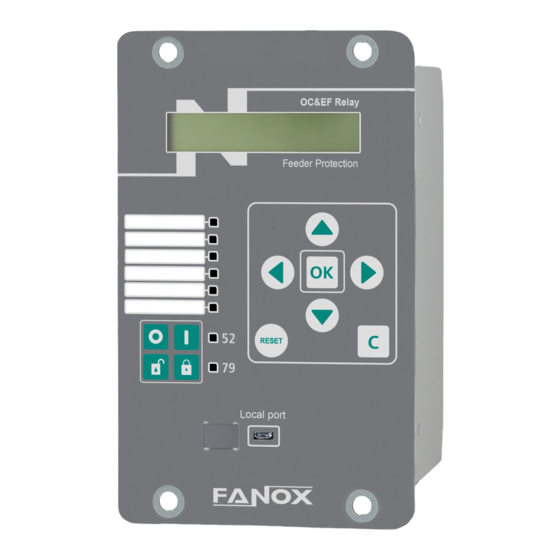
2 DIMENSIONS AND CONNECTION DIAGRAMS 2.1 SILA with standard current terminals 2.1.1 Front view www.fanox.com Rev.04 7/112... -
Page 8: Case Dimensions
2.1.2 Case dimensions The dimensions are in mm: www.fanox.com Rev.04 8/112... -
Page 9: Connection Diagrams
2.1.3 Connection diagrams 2.1.3.1 Analog connections www.fanox.com Rev.04 9/112... -
Page 10: Digital Connections
2.1.3.2 Digital connections Following connection is an example. Configuration can be selected by the user. www.fanox.com Rev.04 10/112... -
Page 11: Terminals
Common digital inputs Phase C current measurement A7-A8 NO digital output 1 Neutral current measurement NC digital output 1 Modbus TCP/IP, DNP3.0 TCP/IP or IEC60870- 104 selectable by settings or IEC61850 selectable by model Common digital output 1 www.fanox.com Rev.04 11/112... -
Page 12: Sila With Short-Circuitable Current Terminals
SILA with short-circuitable current terminals 2.2.1 Front view www.fanox.com Rev.04 12/112... -
Page 13: Case Dimensions
2.2.2 Case dimensions The dimensions are in mm: www.fanox.com Rev.04 13/112... -
Page 14: Connection Diagrams
2.2.3 Connection diagrams 2.2.3.1 Analogic connections www.fanox.com Rev.04 14/112... -
Page 15: Digital Connections
2.2.3.2 Digital connections Following connection is an example. Configuration can be selected by the user. www.fanox.com Rev.04 15/112... -
Page 16: Terminals
Common digital inputs Phase C current measurement A7-A8 NO digital output 1 Neutral current measurement NC digital output 1 Modbus TCP/IP, DNP3.0 TCP/IP or IEC60870- 104 selectable by settings or IEC61850 selectable by model Common digital output 1 www.fanox.com Rev.04 16/112... -
Page 17: Description
Given the need for creating intelligent infrastructures, FANOX has developed the SIL family to carry out this function. The SIL- A relay is designed to protect secondary transformation and distribution centers of electric grids, using current functions. - Page 18 The relay is provided with 1 front communication port. This micro USB port allows a PC to be connected and the relay to be monitored using the SICom program in WINDOWS 7, WINDOWS 8, WINDOWS 8.1 or WINDOWS 10 (supplied by FANOX). The rear communication ports are designed for different functions. While one is used for control,...
- Page 19 1 through configurable inputs (Optional) Trip Output Lockout through PGC ✓ Cold load pickup 60CTS Phase CT Supervision 1 (Optional) Instantaneous phase undercurrent 1 (Optional) Trip block protection for switch 1 (Optional) disconnector Second Harmonic Blocking Zone Selection Interlocking (ZSI) www.fanox.com Rev.04 19/112...
- Page 20 1 Remote port RS485: ModBus RTU or IEC 60870-5-103 or DNP3.0 Serial (by general settings) REMOTE Communication ✓ 1 additional (optional) remote port with the following options: 1 RJ45: Modbus TCP/IP, DNP3.0 TCP/IP or IEC60870-5- 103 or IEC61850 (depending on model) www.fanox.com Rev.04 20/112...
- Page 21 Load Data Profiling 744 records Real-Time Clock (RTC 1 millisecond) ✓ Test menu ✓ Self-diagnosis ✓ Settings Groups By general settings 4 setting groups By inputs Mechanical Dimensions Height x Width: 177 x 107 (mm) Weight 1.5 kg www.fanox.com Rev.04 21/112...
-
Page 22: Functional Diagram
3.3 Functional diagram www.fanox.com Rev.04 22/112... -
Page 23: Selection & Ordering Codes
Default functions: (2) 50 + (2) 50N +(2) 50G + (2) 51 + (2) 51N + (2) 51G + 52 + 50BF + 46 + 79 + 74TCS + CLP + 86 + 49 + SHB + SOTF Example of ordering code: SIL-A SIL A 0 0 0 C 6 F 2 2 A D www.fanox.com Rev.04 23/112... -
Page 24: Phase Ct And Neutral Ct Selection
The function activates at 100% of the preset input and deactivates at 95%. The reset is instantaneous. The accuracy of the Time Delay is equal to the set time delay ±35ms or ±0.5% (whichever is greater). www.fanox.com Rev.04 24/112... -
Page 25: Function Sotf. Switch On To Fault
The function activates at 100% of the preset input and deactivates at 95%. The reset is instantaneous. The accuracy of the Time Delay is equal to the set time delay ±35ms or ±0.5% (whichever is greater). www.fanox.com Rev.04 25/112... -
Page 26: Function 51. Inverse Time Phase Overcurrent
If the unit operates as defined time, the function is activated at 100% of the set tap value, and it deactivates at 95%. If the unit operates with a curve, the function is activated at 110% of the set tap value, and it deactivates at 100%. The reset is instantaneous in both cases. www.fanox.com Rev.04 26/112... -
Page 27: Function 50G. Instantaneous Measured Neutral Overcurrent
The function activates at 100% of the preset input and deactivates at 95%. The reset is instantaneous. The accuracy of the Time Delay is equal to the set time delay ±35ms or ±0.5% (whichever is greater). www.fanox.com Rev.04 27/112... -
Page 28: Function 51G. Inverse Time Measured Neutral Overcurrent
±0.5% (whichever is greater).If a curve is selected for the curve setting, the accuracy of the time delay is equal to the theoretical time ±30ms or ±5% (whichever is greater). The curves used are IEC 60255-151 and IEEE, which are described in the corresponding section. www.fanox.com Rev.04 28/112... -
Page 29: Function 51N. Inverse Time Calculated Neutral Overcurrent
±0.5% (whichever is greater).If a curve is selected for the curve setting, the accuracy of the time delay is equal to the theoretical time ±30ms or ±5% (whichever is greater). The curves used are IEC 60255-151 and IEEE, which are described in the corresponding section. www.fanox.com Rev.04 29/112... -
Page 30: Function 46. Phase Balance Current Protection
±0.5% (whichever is greater).If a curve is selected for the curve setting, the accuracy of the time delay is equal to the theoretical time ±30ms or ±5% (whichever is greater). The curves used are IEC 60255- 151 and IEEE, which are described in the corresponding section. www.fanox.com Rev.04 30/112... -
Page 31: Function 46Bc. Broken Conductor Detection
Tripping time depends on adjusted thermal constants, operative current and previous thermal status of the machine. Thermal image is calculated based on next equation: θ = 100 x (I/It) x (1 – e-t/ζ) + θ’0 x e-t/ζ www.fanox.com Rev.04 31/112... -
Page 32: Thermal Overload Measurement Evolution Graphic
On next graphic, thermal image measurement evolution can be observed depending on applied current Th % 100% alarm trip With the thermal image protection adjusted with a tap of 1.1 times the nominal current and an alarm level of 75%. www.fanox.com Rev.04 32/112... -
Page 33: Thermal Overload With Memory
4.10.3 Thermal overload measurement display. Reset. Thermal image measurement is displayed on Measurement menu. Thermal image value reset is possible in Commands menu (Reset TI). This command reset the value of the thermal image to the value set in the alarm level. www.fanox.com Rev.04 33/112... -
Page 34: Thermal Protection Curves
4.10.4 Thermal protection curves This is the thermal curve for ζ = 3 minutes. www.fanox.com Rev.04 34/112... -
Page 35: Function 37. Instantaneous Phase Undercurrent
100000 1000 Maximum accumulated amperes 100000 M(A²) Repetitive number of openings 100000 Time for repetitive number of openings Maximum opening time 0.020 300.000 0.001 0.10 Maximum closing time 0.020 300.000 0.001 0.10 (*) Optional depending on model www.fanox.com Rev.04 35/112... - Page 36 If no breaker contacts are used, the monitoring of the circuit breaker is made through the current measurement. This is, if less than 0.8% of rated current is detected it is considered the breaker is open and if more than 0.8% of rated current is available, it is considered the breaker is closed. www.fanox.com Rev.04 36/112...
- Page 37 If only the circuit breaker 52a contact is available, it should be wired to the corresponding physical input. This physical input is then assigned to the "52a Input” logical input. The 52b logical input is calculated internally as the negative of 52a. The circuit breaker performance is shown in the following finite state machine: www.fanox.com Rev.04 37/112...
- Page 38 52a contact to the "52a Input" logical input, and the circuit breaker 52b contact to the "52b Input" logical input. The circuit breaker automaton is considered as having eight statuses: Startup, open, closed, error, opening time, opening error, closing time and closing error. The circuit breaker performance is shown in the following finite state machine: www.fanox.com Rev.04 38/112...
-
Page 39: Circuit Breaker Opening And Closing Commands
It works like a time accumulator, to be active it needs to detect openings within the range defined by these two settings. When this number is exceeded, the ‘Openings/Time Alarm’ status is activated, and its corresponding event is generated. This alarm resets itself, when the corresponding time is exceeded with less trips than those indicated. www.fanox.com Rev.04 39/112... -
Page 40: Function 79. Ac Reclosing Device
It must be possible to block the recloser, specially is maintenance tasks are carried out on the substation. To achieve this, there is two logical signals 79Block Command and 79Unblock Command where up to 4 logical inputs can assigned to each one. By default, they are configured as follows: www.fanox.com Rev.04 40/112... - Page 41 Also, this logic signal can be configured to change the Settings Groups through PGC. This can be useful to achieve a fast tripping of protection functions in Hot Line Tag Mode. The auto-recloser´s start up is shown in the following figure: www.fanox.com Rev.04 41/112...
- Page 42 When blocked, the recloser has are two possible paths, depending on if the locked mode is the result ✓ Circuit breaker closing (from manual or remote control): it switches to Standby ✓ Unexpected condition from a reclose cycle: it switches to Safe time. www.fanox.com Rev.04 42/112...
-
Page 43: Counter To Record The Number Of Recloses
This control function can be set by using the following parameters: Group Description Minimum Maximum Step Unit Default Circuit breaker failure 50BF (*) Function Enable No/Yes Time Delay 0.020 1.000 0.001 0.200 (*) Optional depending on model The following automaton describes the open failure function: www.fanox.com Rev.04 43/112... -
Page 44: Function 74Tcs. Trip Circuit Supervision
This protection function can be set by using the following parameters: Function Description Minimum Maximum Step Unit Default Cold Load Pickup Function Enable Yes/No Settings group No Load time 0.020 300.000 0.001 15.000 Cold Load Time 0.020 300.000 0.001 15.000 www.fanox.com Rev.04 44/112... - Page 45 Once the circuit breaker is closed, CLP function picks-up and ‘Cold load time’ starts to count. During this time the relay will work with the new setting group regardless of the circuit breaker situation, this is, without taking into account whether the circuit breaker is maintained closed or is open. www.fanox.com Rev.04 45/112...
-
Page 46: Function 60Cts. Phase Ct Supervision
Switchgears have a limited opening current, so the fuses are responsible for cutting out the circuit for high current short circuits, as the switchgear would be destroyed if opened in this situation. In order to deal with these situations, tripping is blocked when the phase current exceeds a pre-set value. www.fanox.com Rev.04 46/112... -
Page 47: Function Shb. Second Harmonic Blocking
2 when detect the startup of function 50N/50G or 51N/51G. Relays with supply functionality, block the trip of functions 50 and 51 when detect the activation of input 1 and block the trip of functions 50N/50G and 51N/51G when detect the activation of input 2. www.fanox.com Rev.04 47/112... - Page 48 ΔT = Security time (aproximately 40ms) Tos = Time of operation of the supply (ms) Ths = Time of trip holding of the supply (200ms) The inputs of the supply relay should be connected to the blocking signals directly through an OR. www.fanox.com Rev.04 48/112...
- Page 49 When the feeder trips, it is not able to open its breaker so the supply will trip once the block disappears since it can still see the fault. www.fanox.com Rev.04 49/112...
- Page 50 The feeder will block the supply the adjusted time, but in this case, the time of operation of the supply is larger that this blocking time, so the supply will trip once its time of operation finishes since it can still see the fault. www.fanox.com Rev.04 50/112...
-
Page 51: General Settings
The phase and neutral CT transformation ratio setting allows the measurements of the primary values from the protection transformer to be showed. 5.2 DFR Function Description Minimum Maximum Step Unit Default 25x60, 5x260, Num. of Records cycles 25x60 cycles 100x15, 50x30 Cycles Prefault cycles www.fanox.com Rev.04 51/112... -
Page 52: Ldp
Active Settings Group. The Settings groups used by default can be selected with this parameter. 5.5 Inputs Function Description Minimum Maximum Step Unit Default Inputs Debounce time 5 ms 5.6 USB communication Function Description Minimum Maximum Step Unit Default USB Communications Slave Address www.fanox.com Rev.04 52/112... -
Page 53: Rear Serial Communication
Default MODBUS RTU Communications Slave address 5.7.2 DNP3.0 SERIAL Function Description Minimum Maximum Step Unit Default DNP3.0 Communications Slave address Master address 5.7.3 IEC 60870-5-103 Function Description Minimum Maximum Step Unit Default IEC 60870-5-103 Communications Slave address www.fanox.com Rev.04 53/112... -
Page 54: Rear Tcp Communication
20000 5.8.3 IEC 60870-5-104 Function Description Minimum Maximum Step Unit Default IEC 60870-5-104 Communications Slave address Port 65535 2404 5.8.4 IEC 61850 Function Description Minimum Maximum Step Unit Default IEC 61850 Communications Slave address Port 65535 25000 www.fanox.com Rev.04 54/112... -
Page 55: Settings Groups
7 AVALIABLE CURVES 7.1 IEC 60255-151 Curves The SILA relay complies with the curves shown in standard IEC60255-151: • Inverse Curve • Very Inverse Curve • Extremely Inverse Curve • Long time inverse • Short Time Inverse www.fanox.com Rev.04 55/112... - Page 56 0.04 Ext. Inverse Very Inverse 13,5 Inverse 0.14 0.02 The curve can mode from its axis using the D time selection device, which the user can adjust. is the initial operating current, set by the user. adjusted www.fanox.com Rev.04 56/112...
- Page 57 IEC Inverse 1000,00 100,00 Dial 0.05 Dial 0.1 10,00 Dial 0.2 Dial 0.3 Dial 0.4 Dial 0.5 Dial 0.6 Dial 0.7 1,00 Dial 0.8 Dial 1 0,10 0,01 I/It www.fanox.com Rev.04 57/112...
- Page 58 IEC Very Inverse 1000,00 100,00 Dial 0.05 Dial 0.1 10,00 Dial 0.2 Dial 0.3 Dial 0.4 Dial 0.5 Dial 0.6 Dial 0.7 1,00 Dial 0.8 Dial 1 0,10 0,01 I/It www.fanox.com Rev.04 58/112...
- Page 59 IEC Extremely Inverse 1000,00 100,00 10,00 Dial 0.05 Dial 0.1 Dial 0.2 Dial 0.3 Dial 0.4 1,00 Dial 0.5 Dial 0.6 Dial 0.7 Dial 0.8 Dial 1 0,10 0,01 0,00 I/It www.fanox.com Rev.04 59/112...
- Page 60 IEC Long Time Inverse 10000,00 1000,00 100,00 Dial 0.05 Dial 0.1 Dial 0.2 Dial 0.3 Dial 0.4 10,00 Dial 0.5 Dial 0.6 Dial 0.7 Dial 0.8 Dial 1 1,00 0,10 0,01 I/It www.fanox.com Rev.04 60/112...
- Page 61 Rev.04 61/112...
-
Page 62: Ieee Curves
Very Inverse 19.61 2.00 0.491 Inverse 0.0515 0.02 0.114 The curve can move from its axis using the TD time selection device, which the user can adjust. is the initial operating current, set by the user. adjusted www.fanox.com Rev.04 62/112... - Page 63 Rev.04 63/112...
- Page 64 Rev.04 64/112...
- Page 65 Rev.04 65/112...
-
Page 66: Application Examples
=1100 A, IEC inverse curve defines a tripping value of 0.1425s (Figure1) for 50/51 function. It is considered that this time is too high, so when current fault reaches 11xI , definite time overcurrent function will be work. www.fanox.com Rev.04 66/112... - Page 67 Transformation ratio of CT =500/1 • Primary current: I =500 A 50/51 function settings • Curve type: IEEE Extremely Inverse • Dial: 2.20 • Tap: 1xI 50 function settings • Tap: 14xI • Time delay: 0.1 s www.fanox.com Rev.04 67/112...
- Page 68 , definite time overcurrent function will be work. 50 function tap is adjusted at 14xIn so definite time overcurrent function will trip when current fault is higher than 14xIn (50 function does not wait to reach 24xIn) The figure below (Figure 4), shows the tripping curve of the relay: Figure 4. Relay tripping curve www.fanox.com Rev.04 68/112...
-
Page 69: Monitoring And Control
NOTE: If any LED/Alarm has a SRFF or a RSFF configured with the Reset Key as Reset reason, when pressing Reset from standby screen, the LED’s will be reset. However, to recognize the alarms we shall do it from alarms panel menu. www.fanox.com Rev.04 69/112... -
Page 70: States And Sequential Events Recording (Ser)
Events’ option. To delete the events, it is necessary to enter a password. Events have the following structure: Identifier Unique event identifier: e.g.: 51_1.4 = 51 PICKUP ON(Activated) /OFF(Deactivated): Value an event is generated for Activation and deActivation Year Month Time Minutes Seconds Milliseconds www.fanox.com Rev.04 70/112... -
Page 71: Disturbance Fault Recording (Dfr)
Digital channels = 96 COMTRADE = 2 Date/Time = 1/8/2019 - 16:27:36.588 **************************************************************** The following information is included in each COMTRADE file: • Analog channels Number Analog channels Phase A current Phase B current Phase C current Neutral current www.fanox.com Rev.04 71/112... -
Page 72: Load Data Profiling (Ldp)
For each output there is a LOGICAL GATE. It can perform a logical operation up to 4 binary states to obtain other binary result. In V3 of the PGC the LOGICAL GATES that are supported by SIL-A are: www.fanox.com Rev.04 72/112... - Page 73 It is the delay until the configured signal is configured signal) activated TIMER DOWN Time up: OR TD Time up (Delay time to deactivate the It is the delay until the configured signal is configured signal) deactivated www.fanox.com Rev.04 73/112...
- Page 74 It is the delay until the configured signal is configured signal) deactivated TIMER DOWN Time up: NOR TD Time up (Delay time to deactivate the It is the delay until the configured signal is activated configured signal) www.fanox.com Rev.04 74/112...
- Page 75 It is the delay until the configured signal is configured signal) activated TIMER DOWN Time up: AND TD Time up (Delay time to deactivate the It is the delay until the configured signal is deactivated configured signal) www.fanox.com Rev.04 75/112...
- Page 76 It is the delay until the configured signal is configured signal) deactivated TIMER DOWN NAND TD Time up: Time up (Delay time to deactivate the It is the delay until the configured signal is configured signal) activated www.fanox.com Rev.04 76/112...
- Page 77 It is the delay until the configured signal is configured signal) activated TIMER DOWN XOR TD Time up: Time up (Delay time to deactivate the It is the delay until the configured signal is configured signal) deactivated www.fanox.com Rev.04 77/112...
- Page 78 It is the delay until the configured signal is configured signal) activated TIMER DOWN RSFF TD Time up: Time up (Delay time to deactivate the It is the delay until the configured signal is configured signal) deactivated www.fanox.com Rev.04 78/112...
- Page 79 It is the delay until the configured signal is configured signal) activated TIMER DOWN SRFF TD Time up: Time up (Delay time to deactivate the It is the delay until the configured signal is configured signal) deactivated www.fanox.com Rev.04 79/112...
- Page 80 The time the pulse lasts is activated) NOTE: From SICOM both extra parameters (Time up and period can be configured. However, from HMI, only the time up can be configured. See paragraph to check the configuration process through the HMI. www.fanox.com Rev.04 80/112...
- Page 81 The configured signal will make a pulse of the adjusted time in “time up” parameter once the input signal is activated. Input Output TIMER UP The configured signal waits the adjusted time in “time up” parameter to activate itself once the input signal is activated. Input Output www.fanox.com Rev.04 81/112...
- Page 82 TIMER DOWN Once the configured signal is activated, it waits the adjusted time in “time up” parameter to deactivate itself. www.fanox.com Rev.04 82/112...
- Page 83 The configured signal will be activated once the bits in “s” position are activated (set position. The signal is maintained activated until the bits configured in “R” position are activated. Reset mode is configurable by the user and the option of manual reset is available. www.fanox.com Rev.04 83/112...
- Page 84 PULSES (Same time on and time off) The configured signal will make pulses of the adjusted milliseconds while the input signal is activated. Input Output www.fanox.com Rev.04 84/112...
- Page 85 After inserting the password, by pressing OK the action of removing the configured options is confirmed. It is necessary to press RESET key as many times as signals are configured. www.fanox.com Rev.04 85/112...
-
Page 86: Function 86. Trip Lockout
8.11 Configurable Outputs SIL-A is fitted 6 digital outputs. The outputs can be configured from the HMI or through the SICom program. The configuration of the outputs has been described in point 8.7 Programmable Logic Control (PGC). www.fanox.com Rev.04 86/112... -
Page 87: Self-Diagnosis
Measurement Error (*) It is active when there is a problem with the communication between the main CPU and the measurement CPU. (*) This bit is included in the Measurements State www.fanox.com Rev.04 87/112... -
Page 88: Commands
If remote control is used, it is recommended to configure a led to display when it is permitted and when it is not. 8.15 Date/time synchronization The relay can be synchronized from the HMI or by communications. www.fanox.com Rev.04 88/112... -
Page 89: Test Program
8.17 Power Supply SIL-A is designed to be powered with an auxiliary voltage of 24-230 Vac/dc. The supply guarantees between -20%/+10% of the auxiliary voltage. Outside this range the relay could operate, but it is not guaranteed. www.fanox.com Rev.04 89/112... -
Page 90: Technical Specifications And Standards
± 30 ms or ± 5% (greater of both). Timing accuracy for defined time curve selection: ± 35 ms or ± 0.5% (greater of both) Function enable: No/Alarm/Trip/SHB Trip Function 51N-1 (*) Curve Type: IEC 60255-151 and IEEE curves. www.fanox.com Rev.04 90/112... - Page 91 Temporized deactivation Function enable: Yes/No Settings group: 1 to 4 (step 1) Function CLP No load time: 0.020 to 300.000 s (step 0.001 s) Cold load time: 0.020 to 300.000 s (step 0.001 s) Function enable: No/Alarm/Trip/SHB Trip www.fanox.com Rev.04 91/112...
- Page 92 Time delay: 0.020 to 300.000 s (step 0.001 s) Function 60CTS (*) Open breaker activation and reset threshold: 0.8% In Detection of the loss of one phase CT Function enable: No/Yes Function 50BF (*) Time delay: 0.020 to 1.000 s (step 0.001 s) www.fanox.com Rev.04 92/112...
- Page 93 Output 1 (NC + NO) Output 2, Output 3, Output 4, Output 5 and Output 6: NO Frequency 50/60Hz Burden of current inputs: Burden <0.1 mVA (1 A) & <0.5 mVA (5 A) Burden of power supply unit: www.fanox.com Rev.04 93/112...
- Page 94 Relative humidity: 95% Transformers Measurement 3 or 4 CT /5 or /1 (depending on model) Metallic box Panel mounted Mechanical characteristics Height x Width: 177 x 107 (mm) Depth: 122.1 mm IP-54 (*) Optional depending on model www.fanox.com Rev.04 94/112...
-
Page 95: Thermal Resistance
Being the relay set to the secondary nominal current of 5 amperes, the burden for current measuring inputs is: Specified Burden of current inputs: <0.5 mVA (5 A) Measured burden of current inputs: Phase: 0.013 mVA Neutral: 0.331 mVA www.fanox.com Rev.04 95/112... -
Page 96: Burden For Power Supply Unit
24 Vdc (50% load): 4.55 W 230 Vdc (quiescent): 3.76 W 230 Vdc (50% load): 4.35 W 24 Vac (quiescent): 6.24 VA 24 Vac (50% load): 8.25 VA 230 Vac (quiescent): 11.94 VA 230 Vac (50% load): 13.63 VA www.fanox.com Rev.04 96/112... -
Page 97: Burden For Binary Input
230 Vdc: <200 mW 24 Vac: <50 mW 230 Vac: < 500 mW Measured Burden for binary inputs 24 Vdc activation: 9.36 mW 230 Vdc activation: 167.9 mW 24 Vac activation: 33.29 mVA 230 Vac activation: 380.72 mVA www.fanox.com Rev.04 97/112... -
Page 98: Communication And Hmi
Resistors should be used at each end if very long cables are used. The best solution for avoiding reflection is to install resistors at both ends of the cable. The ohm value of these resistors must be equal to the cable impedance value. www.fanox.com Rev.04 98/112... -
Page 99: Lcd And Keypad
This membrane keyboard has 6 keys that can be used to navigate through the different menus and to change the setting parameters. The ▲ ▼ and ◄ ► keys can be used to navigate through the different menus, the different options in each menu and the different values for the settings parameters. www.fanox.com Rev.04 99/112... -
Page 100: Sicom Communications Program
Read and delete DFR • Configure and check the demand (LDP) • Date-time synchronisation • Set Counters • Execute Commands • Changing the user passwords • Loading settings files • Loading configuration files • Checking the versions of the relay www.fanox.com Rev.04 100/112... -
Page 101: How To Install Sicom Software
10.4.1 How to install SICOM Software To install the SICom it is necessary the following link: http://fanox.blob.core.windows.net/sicom/publish.htm The link will open the next screen, where key ‘Install’ must be pressed: The necessary drivers depending on the operative system can be downloaded from this page. -
Page 102: Setting Up The Session: Password And Access Levels
Upgrade the Change Status and settings Commands Configuration FW (flashing manufacturer´s measurements process) Configuration Set Counters Settings Delete Events Configuration Delete DFR Events/DFR Fanox/ 0000 Fanox/ 1111 Fanox/ 2222 Fanox/ 3333 Fanox/ 6666 Fanox/ 7777 Fanox/ 8888 Fanox/ 4444 Fanox/ 5555 www.fanox.com... -
Page 103: Menus
13/01/19 13:51:44825 Even if auxiliary power is lost, when the SIL-A regains power, it will retain information on the last trip. The last trip screen will only disappear when the ‘RESET’ button is pressed and held down. www.fanox.com Rev.04 103/112... -
Page 104: Accessing The Menus
From the standby mode screen, hold the ‘▲’ key to access to the relay versions where the microcontrollers software versions are displayed. Pressing ‘C’ key it is returned to the standby screen. ▲ M05.00.01-I03.01 SILA000C6F22AD Sn:12345678 0.00 0.00 0.00 0.00 www.fanox.com Rev.04 104/112... -
Page 105: Contrast
From the standby mode screen, hold the ‘◄’ key to visualize contrast menu. Pressing ‘▲’ and ‘▼’ keys the contrast level can be changed. Pressing ‘C’ key it is returned to the standby screen. ◄ CONTRAST SILA000C6F22AD 0.00 0.00 0.00 0.00 www.fanox.com Rev.04 105/112... -
Page 106: Funcional Menu
• Settings Group. • Alarms panel. • Events (SER). • Fault recorder. • LDP. • Counters. • Commands. • Date/time. SILA000C6F22AD SILA000C6F22AD MEASUREMENTS 0.00 0.00 0.00 0.00 0.00 0.00 0.00 0.00 ▲▼ STATES GENERAL ▲▼ SETTINGS www.fanox.com Rev.04 106/112... - Page 107 Press the ‘OK’ key to access the second level from the main screen. Use the ▲ and ▼ keys to move from one menu section to another in the second level. Use the ‘C’ key to return to a higher level. www.fanox.com Rev.04...
-
Page 108: Settings Menu
↓ ↑ SETTINGS GROUP ▲▼ ↓ ↑ SETTINGS GROUP ▲▼ ↓ ↑ SETTINGS GROUP ▲▼ ↓ 50-1 ↑ SETTINGS GROUP ↓ 50-2 ↑ SETTINGS GROUP ↓ 51-1 ↑ SETTINGS GROUP ↓ 51-2 ↑ SETTINGS GROUP ↓ SOTF www.fanox.com Rev.04 108/112... - Page 109 SETTINGS GROUP ↓ 50N-2 ↑ SETTINGS GROUP ↓ 51G-1 ↑ SETTINGS GROUP ↓ 51G-2 ↑ SETTINGS GROUP ↓ 51N-1 ↑ SETTINGS GROUP ↓ 51N-2 ↑ SETTINGS GROUP ↓ 50BF ↑ SETTINGS GROUP ↓ SETTINGS GROUP ↑ 46BC www.fanox.com Rev.04 109/112...
- Page 110 ↓ ↑ SETTINGS GROUP ↓ ↑ SETTINGS GROUP ↓ ↑ SETTINGS GROUP ↓ 74TCS ↑ SETTINGS GROUP ↓ 60CTS www.fanox.com Rev.04 110/112...
-
Page 111: Appendix
11 APPENDIX NOTES: …………………………………………………………………………………………………..…… …………………………………………………………………………………………………..…… …………………………………………………………………………………………………..…… …………………………………………………………………………………………………..…… …………………………………………………………………………………………………..…… …………………………………………………………………………………………………..…… …………………………………………………………………………………………………..…… …………………………………………………………………………………………………..…… …………………………………………………………………………………………………..…… …………………………………………………………………………………………………..…… …………………………………………………………………………………………………..…… …………………………………………………………………………………………………..…… …………………………………………………………………………………………………..…… …………………………………………………………………………………………………..…… …………………………………………………………………………………………………..…… …………………………………………………………………………………………………..…… …………………………………………………………………………………………………..…… …………………………………………………………………………………………………..…… …………………………………………………………………………………………………..…… …………………………………………………………………………………………………..…… …………………………………………………………………………………………………..…… …………………………………………………………………………………………………..…… …………………………………………………………………………………………………..…… …………………………………………………………………………………………………..…… …………………………………………………………………………………………………..…… …………………………………………………………………………………………………..…… …………………………………………………………………………………………………..…… www.fanox.com Rev.04 111/112... - Page 112 Bizkaia Technology Park Building, 604 Derio, 48160 Bizkaia SPAIN T. +34 94 471 14 09 fanox@fanox.com www.fanox.com www.fanox.com www.fanox.com Rev.04 112/112...
Need help?
Do you have a question about the SIL-A A Series and is the answer not in the manual?
Questions and answers