
Related Manuals for FANOX SIL-A


Summary of Contents for FANOX SIL-A
- Page 1 SIL-A Overcurrent & Earth Fault Protection Relay USER’S MANUAL USER’S MANUAL EN_FANOXTD_MANU_SIL_Ocefprimarydist_SILA_R036.Docx...
-
Page 2: Table Of Contents
Functional diagram ..................... 26 Selection & Ordering codes ..................27 Phase CT and neutral CT selection ................28 3.5.1 Load Curve for SIL-A (1A) ..................29 3.5.2 Load Curve for SIL-A (5A) ..................29 PROTECTION FUNCTIONS ..................30 Function 50. Instantaneous phase overcurrent ............30 Function 50/51. - Page 3 Load Data Profiling (LDP) ..................69 Counters ........................69 States and Events ....................... 70 Disturbance Fault Recording (DFR) ................79 8.5.1 SIL-A Adaptation B ..................... 81 8.5.2 SIL-A Adaptation C ..................... 82 Configurable inputs ....................83 Digital outputs ......................84 Programmable Logic Control (PGC) .................
- Page 4 8.8.1 SIL-A Adaptation B ..................... 84 8.8.2 SIL-A Adaptation C ..................... 88 Function 86. Trip output lockout ................94 8.10 Self-diagnosis ......................94 8.11 Commands ........................95 8.12 Remote Control ......................95 8.13 Date/time synchronization ..................95 8.14 Test program ....................... 96 8.14.1...
- Page 5 Test menu: ......................... 202 11.4 Register of commissioning settings: ..............202 11.5 Inputs: ........................206 11.6 Outputs: ........................206 11.7 LEDs:.......................... 207 11.7.1 Leds configuration template:................... 207 11.8 Logical signals ......................208 11.9 Comments ......................... 210 www.fanox.com Rev. 36 5/212...
-
Page 6: Reception, Handling, Installation
It is necessary to inspect the device at the time it is delivered to ensure that the relays have not been damaged during transport. If any defect is found, the transport company and FANOX should be informed immediately. If the relays are not for immediate use, they should be returned to their original packaging. -
Page 7: Installation, Commissioning And Service
Fanox Electronic, S.L. adheres itself to the 1st additional disposal of the Spanish 11/97 Standard in which it is said that the final user of the containers should give them, properly segregated by materials, to an authorized recovery, recycler or valuer company. -
Page 8: Dimensions And Connection Diagrams
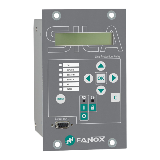
DIMENSIONS AND CONNECTION DIAGRAMS 2.1 SILA LPCT model (SILAXX) 2.1.1 Front view www.fanox.com Rev. 36 8/212... -
Page 9: Case Dimensions
2.1.2 Case dimensions The dimensions are in mm: www.fanox.com Rev. 36 9/212... -
Page 10: Cut-Out Pattern
2.1.3 Cut-out pattern www.fanox.com Rev. 36 10/212... -
Page 11: Connection Diagrams
2.1.4 Connection diagrams Analog connections Digital connections Following connection is an example. Configuration can be selected by the user. www.fanox.com Rev. 36 11/212... -
Page 12: Terminals
2.1.5 Terminals www.fanox.com Rev. 36 12/212... - Page 13 (*) When the model is chosen is very important to choose the communications protocols correctly. If ‘RS485’ port is chosen, then ‘E’ communications module is not available. If ‘E’ communications module is chosen, then ‘RS485’ port is not available. www.fanox.com Rev. 36 13/212...
-
Page 14: Standard Sila
2.2 Standard SILA 2.2.1 Front view www.fanox.com Rev. 36 14/212... -
Page 15: Case Dimensions
2.2.2 Case dimensions The dimensions are in mm: www.fanox.com Rev. 36 15/212... -
Page 16: Cut-Out Pattern
2.2.3 Cut-out pattern www.fanox.com Rev. 36 16/212... -
Page 17: Connection Diagrams
2.2.4 Connection diagrams Analog connections www.fanox.com Rev. 36 17/212... -
Page 18: Digital Connections
Digital connections Following connection is an example. Configuration can be selected by the user. www.fanox.com Rev. 36 18/212... -
Page 19: Terminals
2.2.5 Terminals www.fanox.com Rev. 36 19/212... - Page 20 (*) When the model is chosen is very important to choose the communications protocols correctly. If ‘RS485’ port is chosen, then ‘E’ communications module is not available. If ‘E’ communications module is chosen, then ‘RS485’ port is not available. www.fanox.com Rev. 36 20/212...
-
Page 21: Description
The energy sector is currently immersed in a deep change worldwide. As a result of high levels of energy demand more distribution lines and advanced supervision systems are required. Given the need for creating intelligent infrastructures, FANOX has developed the SIL family to carry out this function. - Page 22 The SIL-A relay has 4 outputs that can be set by the user and configurable inputs that depending on model will be: 6 configurable inputs for adaptation B. 4 configurable inputs and 2 non-configurable inputs dedicated for 74TCS function for adaptation C.
- Page 23 Trip block for switch disconnector 1 (Optional) block * SHB * Second Harmonic Blocking 1 (Optional) *SIL-A relay has as optional SHB or Trip block, but it is not possible to have both in the same device www.fanox.com Rev. 36 23/212...
- Page 24 1 Remote port RS485: ModBus RTU or IEC 60870-5-103 (by REMOTE Communication general settings) 1 Remote port RS485: ModBus RTU or DNP3.0 (by general settings) 1 RJ45: IEC61850, DNP3.0, IEC 60870-104 or Modbus TCP/IP (depending on model) www.fanox.com Rev. 36 24/212...
- Page 25 4U x 1 4 ⁄ ��ack Dimensions Weight 1.5 kg (**) LPCT model→50N/G and 50/51N/G : calculated neutral; in Standard model→50N/G and 50/51N/G: measured neutral (1*) On SIL-AXX models(LPCT type), the accuracy of the measurement in the neutral is 8% www.fanox.com Rev. 36 25/212...
-
Page 26: Functional Diagram
3.3 Functional diagram www.fanox.com Rev. 36 26/212... -
Page 27: Selection & Ordering Codes
Without 50-2, 50G-2 and 50BF (74TCS with dedicated inputs) → LPCT model 50N and 50/51N: calculated neutral → Standard model 50N/G and 50/51N/G: measured neutral Not all combinations are possible. Please, confirm with Fanox chosen model. www.fanox.com Rev. 36 27/212... -
Page 28: Phase Ct And Neutral Ct Selection
To ensure the relay functions correctly, a suitable current transformer must be used. The load of the relay’s own measurement circuits and the load on the cables that connect the CTs and the relay must be considered. ACCURACY BURDEN RELAYS 5P10 0.5 VA SIL-A/1 5P20 0.5 VA SIL-A/1 5P30 0.5 VA SIL-A/1 5P10 0.5 VA... -
Page 29: Load Curve For Sil-A (1A)
3.5.1 Load Curve for SIL-A (1A) 0,04 0,03 0,02 0,01 SILA/1 Circuito de Medida SILA/1 Measurement Circuit 3.5.2 Load Curve for SIL-A (5A) 0,08 0,06 0,04 0,02 SILA/5 Measurement Circuit www.fanox.com Rev. 36 29/212... -
Page 30: Protection Functions
SHB option and T=0.00 s available only in SILAxxxx4xxxxx model. For other models the minimum is T=0.02 s. IEC Inverse, IEC Very Inverse, IEC Extremely Inverse, IEC Long Time Inverse, IEEE Inverse, IEEE Very Inverse, IEEE Extremely Inverse, Defined Time www.fanox.com Rev. 36 30/212... -
Page 31: Function 50G. Instantaneous Measured Neutral Overcurrent
(trips) and does not reset itself until the average value of the phase drops below the point of current tap. The function activates at 100% of the preset input and deactivates at 95%. The reset is instantaneous. www.fanox.com Rev. 36 31/212... -
Page 32: Function 50/51G. Inverse Time Measured Neutral Overcurrent
If a curve is selected for the curve setting, the accuracy of the time delay is equal to the preset time ±30 ms or ±5% (whichever is greater). The curves used are IEC 60255-151 and IEEE, which are described in the corresponding section. www.fanox.com Rev. 36 32/212... -
Page 33: Function 46. Phase Balance Current Protection
If a curve is selected for the curve setting, the accuracy of the time delay is equal to the preset time ±30 ms or ±5% (whichever is greater). The curves used are IEC 60255-151 and IEEE, which are described in the corresponding section. www.fanox.com Rev. 36 33/212... -
Page 34: Function 46Bc. Broken Conductor Detection
The accuracy of the time delay is equal to: The set time delay ±30ms or ±0.5% (whichever is greater) if 0.02 s <time delay<300 s. The set time delay ±50ms or ±0.5% (whichever is greater) if 0.00 s <time delay<0.02 s www.fanox.com Rev. 36 34/212... -
Page 35: Function 49. Thermal Image
A configurable level is established in order to generate an alarm. If a trip happens, the overload function is reset when thermal image is below to the adjusted alarm level. www.fanox.com Rev. 36 35/212... -
Page 36: Thermal Image Measurement Evolution Graphic
Thermal image measurement is displayed on Measurement menu. Thermal image value reset is possible in Commands menu (Reset TI). This command reset the value of the thermal image to the value set in the alarm level. www.fanox.com Rev. 36 36/212... -
Page 37: Thermal Protection Curves
The relay has 6 configurable inputs and any of them can be configured as external trip input. This input is normally connected to a bimetallic contact fitted to the power transformer. This serves as a backup to the overcurrent functions. www.fanox.com Rev. 36 37/212... -
Page 38: Function 52. Circuit Breaker Monitoring
Number of Repetitive Openings’ during the time set in ‘Time of Repetitive Configured number of openings in a time frame alarm Openings‘. It works like a time accumulator, to be active it needs to detect openings within the range defined by these two settings. www.fanox.com Rev. 36 38/212... - Page 39 This physical input is then assigned to the ‘52b Input’ logical input. The 52a logical input is calculated internally as the negative of 52b. The circuit breaker performance is shown in the following finite state machine: www.fanox.com Rev. 36 39/212...
- Page 40 ‘52b’ logic signal. The circuit breaker's automaton is considered as having eight statuses: Startup, open, closed, error, opening time, opening error, closing time and closing error. The circuit breaker performance is shown in the following finite state machine: www.fanox.com Rev. 36 40/212...
-
Page 41: Circuit Breaker Opening And Closing Commands
Maximum openings in a time window As well as counting the number of times the circuit breaker opens, the SIL-A relay sets up a time window and the maximum number of openings allowed during this time. Both parameters can be adjusted. -
Page 42: Function 50Bf. Circuit Breaker Opening Failure
If the phase current exceeds its predetermined value for an equal or greater amount of time than this preset value, the protection function activates (trips) and does not reset itself until the average value of the phase drops below the point of current pickup (8%In). www.fanox.com Rev. 36 42/212... -
Page 43: Function 74Tcs. Trip Circuit Supervision
Lockout state. Each reclosing cycle has its own specific operation time (Reclose # Time) that can be set independently. Up to 4 logical signals can be configured to the reclosing start (logic signal - 79 Start) www.fanox.com Rev. 36 43/212... - Page 44 ✓ Closing Time: During this state the recloser sends a closing command and for this reason, if you wish to associate an output to that command, the output must be set to the 79 Closing Time bit. www.fanox.com Rev. 36 44/212...
- Page 45 It must be possible to block the recloser, particularly if maintenance tasks are carried out on the substation. There are several SIL-A blocking and unblocking possibilities: ✓ From the HMI. There is a specific key marked 79, plus a specific signal led, allowing recloser operation, blocking or unblocking it.
- Page 46 ✓ Recloser block, via a command. ✓ Manual or remote control opening of the circuit breaker. In this situation it shall await the manual opening of the same, and then it shall switch to lock mode. www.fanox.com Rev. 36 46/212...
-
Page 47: Counter To Record The Number Of Reclosings
Blocking command) and with the closing of the circuit breaker. 4.12.1 Counter to record the number of reclosings The SIL-A relay is fitted with a counter that records the number of reclosings. 4.13 Function CLP. Cold Load Pickup This protection function can be set by using the following parameters:... -
Page 48: Function 74Ct. Phase Ct Supervision
Step Unit Default Phase CT Supervision 74CT (*) Function Enable Yes/No Time Delay 0.02 300.00 0.01 2.00 (*) Optional depending on model Current transformer supervision is provided to detect the loss of one of the phases. www.fanox.com Rev. 36 48/212... -
Page 49: Function 37. Instantaneous Phase Undercurrent
The function pickup occurs at 100% of the adjusted input and the dropout at 105%. The reset type is instantaneous. The accuracy of the time delay is equal to the pre-set time ±30 ms or ±0.5% (whichever is greater). www.fanox.com Rev. 36 49/212... -
Page 50: Function Tb. Trip Block For Switch Disconnector
The function picks-up at 100% off the adjusted input and the dropout is at 95%. The reset type will depend on the adjusted reset time. www.fanox.com Rev. 36 50/212... -
Page 51: Function 68. Zone Selection Interlocking (Zsi)
PULSE operation. The adjusted time must be the time of feeder’s functions (time delay setting), plus the trip holding time (in SIL-A this time is around 200 ms), plus the security time (to ensure the signal has dropped off). - Page 52 ΔT = Security time (aproximately 40ms) Tos = Time of operation of the supply (ms) Ths = Time of trip holding of the supply (200ms) The inputs of the supply relay should be connected to the blocking signals directly through an www.fanox.com Rev. 36 52/212...
- Page 53 The supply will not trip because the feeder makes the fault disappear before its time of operation is finished. www.fanox.com Rev. 36 53/212...
- Page 54 The feeder will block the supply the adjusted time, but in this case, the time of operation of the supply is larger that this blocking time, so the supply will trip once its time of operation finishes since it can still see the fault. www.fanox.com Rev. 36 54/212...
-
Page 55: General Settings
DNP3.0 or Modbus RTU; ModbusTCP/IP or DNP3.0 TCP/IP) Next points must be considered referring general settings: The settings can be changed either from the HMI or through communications. Any change of set values will restart all functions, irrespective they are activated or not. www.fanox.com Rev. 36 55/212... -
Page 56: Settings Group
If the use of both inputs is not required, then one can be used, but depending on which is used, operation can be done with Setting group 1 or Setting group 2. www.fanox.com Rev. 36 56/212... -
Page 57: Avaliable Curves
Ext. Inverse Very Inverse 13,5 Inverse 0,14 0,02 The curve can mode from its axis using the D time selection device, which the user can adjust. is the initial operating current, set by the user. adjusted www.fanox.com Rev. 36 57/212... - Page 58 Rev. 36 58/212...
- Page 59 Rev. 36 59/212...
- Page 60 Rev. 36 60/212...
- Page 61 Rev. 36 61/212...
-
Page 62: Ieee Curves
Very Inverse 19,61 0,491 Inverse 0,0515 0,02 0,114 The curve can move from its axis using the TD time selection device, which the user can adjust. is the initial operating current, set by the user. adjusted www.fanox.com Rev. 36 62/212... - Page 63 IEEE Inverse 1000,000 100,000 Dial 0,05 10,000 Dial 0,1 Dial 0,2 Dial 0,5 Dial 0,8 Dial 1 Dial 1,2 Dial 1,5 1,000 Dial 2 0,100 0,010 10,0 100,0 I/It www.fanox.com Rev. 36 63/212...
- Page 64 IEEE Very Inverse 1000,000 100,000 Dial 10,000 0,05 Dial 0,1 Dial 0,2 Dial 0,5 Dial 0,8 Dial 1 Dial 1,2 Dial 1,5 1,000 Dial 2 0,100 0,010 10,0 100,0 I/It www.fanox.com Rev. 36 64/212...
- Page 65 IEEE Extremely Inverse 1000,000 100,000 Dial 0,05 10,000 Dial 0,1 Dial 0,2 Dial 0,5 Dial 0,8 Dial 1 Dial 1,2 Dial 1,5 Dial 2 1,000 Dial 2,2 0,100 0,010 10,0 100,0 I/It www.fanox.com Rev. 36 65/212...
-
Page 66: Application Examples
Primary current: I =100 A 50/51 function settings • Curve type: IEC Inverse • Dial: 0.05 • Tap: 1xI 50 function settings • Tap: 11xI • Time delay: 0.05 s Figure 1. 50 y 50/51 IEC Inverse www.fanox.com Rev. 36 66/212... - Page 67 Transformation ratio of CT =500/1 • Primary current: I =500 A 50/51 function settings • Curve type: IEEE Extremely Inverse • Dial: 2.20 • Tap: 1xI 50 function settings • Tap: 14xI • Time delay: 0.1 s www.fanox.com Rev. 36 67/212...
- Page 68 14xIn so definite time overcurrent function will trip when current fault is higher than 14xIn (50 function does not wait to reach 24xIn) The figure below (Figure 4), shows the tripping curve of the relay: Figure 4. Relay tripping curve www.fanox.com Rev. 36 68/212...
-
Page 69: Monitoring And Control
(although the function is set in percentage). 8.2 Load Data Profiling (LDP) SIL-A relay provides the demand of current with the following characteristics: • Number of records: 168 •... -
Page 70: States And Events
‘Delete Events’ option. To delete the events, it is necessary to enter a password. Events have the following structure: Identifier Unique event identifier: e.g.: 51_1.4 = 50/51 PICKUP ON(Activated) /OFF(Deactivated): Value an event is generated for Activation and deActivation Year Month Time Minutes Seconds Milliseconds www.fanox.com Rev. 36 70/212... - Page 71 Ground Pickup Phase A Trip Phase B Trip Phase C Trip Ground Trip 50 Trip 50N Trip Phase Trip New DFR Activation/Deactivation Fault report NO. Active group by input Activation Setting group NO. Events erased Activation www.fanox.com Rev. 36 71/212...
- Page 72 50_2 Phase A trip Activation Phase A current 50_2 Phase B trip 50_2 Phase B trip Activation Phase B current 50_2 Phase C trip 50_2 Phase C trip Activation Phase C current 50_2 Trip 50_2 Trip Activation www.fanox.com Rev. 36 72/212...
- Page 73 Neutral current 50/51N/G 50/51N/G Trip 50/51N/G Trip Activation/Deactivation Neutral current Cold Load Pickup CLP Disable 52 Close 52 Open 52 definitive Open Close Cold Load Open Cold Load Activation/Deactivation Cold load Pickup Phase current Cold Load pickup www.fanox.com Rev. 36 73/212...
- Page 74 52 Excessive 52 Excessive Activation/Deactivation accumulated amperes accumulated amperes (I2t). (I2t). 52 Excessive openings in 52 Excessive openings in Activation/Deactivation a time window a time window 52 a 52 a Activation/Deactivation 52 b 52 b Activation/Deactivation www.fanox.com Rev. 36 74/212...
- Page 75 Trip Block for switch disconnector / SHB (**) Phase A Block Phase A Block Activation/Deactivation Phase B block Phase B block Activation/Deactivation Trip Block / SHB (*) Activation/Deactivation Phase C block Phase C block Activation/Deactivation Phase Block Phase Block www.fanox.com Rev. 36 75/212...
- Page 76 52 a 52 a Activation/Deactivation 52 b 52 b Activation/Deactivation External trip External trip Activation/Deactivation 50BF Start 50BF Start Activation/Deactivation DFR Start DFR Start Activation/Deactivation 50/51 Block 50 Block Activation/Deactivation 50/51G Block 50N/G Block Activation/Deactivation Reset Reset www.fanox.com Rev. 36 76/212...
- Page 77 Activation Command identifier 79 Unblock 79 Unblock Activation Command identifier Local control Local control Activation Command identifier Remote Control Remote Control Activation Command identifier Reset Reset Activation Command identifier Reset TI Reset TI Activation Command identifier www.fanox.com Rev. 36 77/212...
- Page 78 (*) Optional depending on model (**) The SIL-A will have the SHB or the Trip block as optional function, it is not possible to have both optional functions in the same model. A brief description of the general states is given below: •...
-
Page 79: Disturbance Fault Recording (Dfr)
The format of a COMTRADE header file can be shown below: ******************** .HDR COMTRADE **************************** *************************************************************** Cycles pre-fault = 3 Total cycles = 100 Analog channels = 4 Digital channels = 48 COMTRADE = 2 Date/Time = 1/8/2019 - 16:27:36.588 **************************************************************** www.fanox.com Rev. 36 79/212... - Page 80 A DFR starts when the configurable logical signal ‘DFR Start’ signal is activated. The default configuration is as follows: It is possible to visualize the DFR using SICom software and to save it as a COMTRADE file. www.fanox.com Rev. 36 80/212...
-
Page 81: Sil-A Adaptation B
8.5.1 SIL-A Adaptation B The following information is included in each COMTRADE record: Number Analog channels Phase A current Phase B current Phase C current Neutral current This current is already in primary amps. As well as the analogue magnitudes, the relay saves 48 digital records, with the same precision as 16 cycle samples. -
Page 82: Sil-A Adaptation C
8.5.2 SIL-A Adaptation C The following information is included in each COMTRADE file: Number Analog channels Phase A current Phase B current Phase C current Neutral current This current is already in primary amps. As well as the analogue magnitudes, the relay saves 37 digital records, with the same precision as 16 cycle samples. -
Page 83: Configurable Inputs
8.6 Configurable inputs The SIL-A adaptation B has 6 digital inputs that can be set by the user. The adaptation C has also 6 digital inputs, but two of them, 74TCS A and 74TCS B are configured to supervise the trip circuit. -
Page 84: Digital Outputs
8.7 Digital outputs SIL-A is fitted 4 digital outputs. The outputs can be configured from the HMI or through the SICom program. The configuration of the outputs is described in point 8.8 Programmable Logic Control. 8.8 Programmable Logic Control (PGC) Firstly, it is defined the concept of physical input, physical output and logical signal. - Page 85 79 Start 79 Enable 79 Level Block 79 Block LOGICAL SIGNALS 79 Unblock Block 50/51 Block 50/51G Reset Settings group 1 Settings group 2 74TCS Continuity A 74TCS Continuity B Logic Signal 1 Logic Signal 2 www.fanox.com Rev. 36 85/212...
- Page 86 Local close breaker PHYSICAL Output 3 • Remote Modbus close breaker OUTPUTS • Remote DNP3.0 close breaker • General trip • Local open breaker Output 4 • Remote Modbus open breaker • Remote DNP3.0 open breaker www.fanox.com Rev. 36 86/212...
- Page 87 79 Enable Not configured 79 Level Block Not configured 79 Block Not configured 79 Unblock Not configured 74TCS Continuity A Not configured 74TCS Continuity B Not configured Logical signal 1 Not configured Logical signal 2 Not configured www.fanox.com Rev. 36 87/212...
-
Page 88: Sil-A Adaptation C
8.8.2 SIL-A Adaptation C LED 1 LED 2 LED 3 LED 4 LEDs LED 5 LED 6 LED 52 LED 79 Output 1 Output 2 PHYSICAL OUTPUTS Output 3 Output 4 External Trip 50/51 Block 50/51N/G Block LOGICAL SIGNALS Settings group 1... - Page 89 PHYSICAL • 79 Closing time OUTPUTS • Local close breaker Output 3 • Remote modbus close breaker • Remote DNP3.0 close breaker • General trip Output 4 • Local open breaker • Remote modbus open breaker www.fanox.com Rev. 36 89/212...
- Page 90 Remote DNP3.0 reset LOGICAL SIGNALS Settings group 1 Not configured Settings group 2 Not configured • General trip 79 Start 79 Enable Not configured 79 Level Block Not configured 79 Block Not configured 79 Unblock Not configured www.fanox.com Rev. 36 90/212...
- Page 91 For each output there is a LOGICAL GATE. It can perform a logical operation up to 4 binary states to obtain other binary result. n V3 of the PGC the LOGICAL GATES that are supported by SIL-A are: LOGICAL GATE...
- Page 92 In the SICom the logic is as follows: Logical gate selection guide The configured signal will make a pulse of the adjusted milliseconds once the input signal is activated. Input Output The configured signal waits the adjusted milliseconds to activate itself. Input Output www.fanox.com Rev. 36 92/212...
- Page 93 The configured signal will be activated till it is externally reset (command, reset key, communications…), though the input signal drops off. Input Output The configured signal will make pulses of the adjusted milliseconds while the input signal is activated. Input Output www.fanox.com Rev. 36 93/212...
-
Page 94: Function 86. Trip Output Lockout
The following status bits are associated with this process: Measurement error Problem in the measurement block Eeprom Error Problem in the eeprom memory, a setting group is corrupt. Event error Problem in the events recording www.fanox.com Rev. 36 94/212... -
Page 95: Commands
If remote control is used, it is recommended to configure a led to display when it is permitted and when it is not. 8.13 Date/time synchronization The relay can be synchronized from the HMI or by communications. www.fanox.com Rev. 36 95/212... -
Page 96: Test Program
8.14 Test program The SIL-A relay is equipped with a test menu from where the led and outputs operation can be checked. The following tables show the components that can be tested, along with their status depending on whether they are activated or deactivated: From standby screen, press ◄,▼,►... -
Page 97: Sil-A Adaptation C
Output 4 activated 8.15 Power Supply SIL-A is designed to be powered with an auxiliary voltage of 24-230 Vac/dc. The relay power consumption is less than 4 watts. The supply guarantees between -20%/+10% of the auxiliary voltage. Outside this range the relay could operate, but this is not guaranteed. -
Page 98: Date And Time By Real Time Clock (Rtc)
Local protocol. The performance is identical to the HMI, the relay synchronises the date and time and executes a new synchronisation event. Remote protocols. These protocols can include continuous synchronisation sections. For this reason, the execution of synchronisation events is inappropriate. www.fanox.com Rev. 36 98/212... -
Page 99: Technical Specifications And Standards
TECHNICAL SPECIFICATIONS AND STANDARDS 9.1 Technical Specifications 9.1.1 SIL-A Adaptation B Function Enable : Yes/No Current Tap: 0.10 to 30 xIn (step 0.01) Time Delay: 0.02 to 300 s (step 0.01 s) 50_1 Activation level 100% 50_2 Deactivation level 95% Instantaneous deactivation Timing accuracy: ±30 ms or ±0.5% (greater of both) - Page 100 ± 30 ms or ± 5% (greater of both). Timing accuracy for defined time curve selection: ± 30 ms or ± 0.5% (greater of both). Function Enable : Yes/No Current Tap: 0.10 to 7.00 xIn (step 0.01) Curves IEC 60255-151 and IEEE www.fanox.com Rev. 36 100/212...
- Page 101 Open circuit breaker reset threshold: 10% In Function Enable : Yes/No Time Delay: 0.02 to 1.00 s (step 0.01 s) 50BF Open circuit breaker activation threshold: 8% In Open circuit breaker reset threshold: 10% In Configurable function pickup www.fanox.com Rev. 36 101/212...
- Page 102 Allows to latch (lock out) the contact trip due to programmable logic (PLC: LATCH). Available through configurable inputs thanks to the programmable logic Function Enable : Yes/No 49 (*) Current Tap: 0.1 to 2.4 xIn (step 0.01) www.fanox.com Rev. 36 102/212...
- Page 103 Time Delay: 0.02 to 300 s (step 0.01 s) Timing accuracy: ±30 ms or ±0.5% (greater of both) Function Enable : Yes/No TB (*) Current Tap: 1.5 to 20 x In (step 0.01) Available through configurable inputs and outputs thanks to programmable logic www.fanox.com Rev. 36 103/212...
- Page 104 Output 3 and output 4: NO Frequency 50/60 Hz selectable by general settings Phase current (IA, IB, IC), neutral (IN), positive sequence (I1), negative sequence(I2), maximum current Current (Imax) and thermal image (TI) measurement Fundamental values (DFT) www.fanox.com Rev. 36 104/212...
- Page 105 Metallic box Panel mounted. Height x Width: 177 x 107 (mm) Mechanical Characteristics Depth: 122.1 mm Weight: 1.5 Kg IP-54 on pannel (*) Optional depending on model LPCT model→50N/G, 50/51N: calculated neutral; Standard model→50N/G, 50/51N/G: measured neutral www.fanox.com Rev. 36 105/212...
-
Page 106: Sil-A Adaptation C
9.1.2 SIL-A Adaptation C Function Enable : Yes/No/SHB Current Tap: 0.10 to 30 xIn (step 0.01) Time Delay: 0.00 to 300 s (step 0.01 s) Activation level 100% 50_1 Deactivation level 95% Instantaneous deactivation Timing accuracy: If Time Delay 0.00 to 0.02 s: ± 50 ms or ± 0.5% (greater of both). - Page 107 Timing accuracy for defined time curve selection: If Time Delay 0.00 to 0.02 s: ± 50 ms or ± 0.5% (greater of both). If Time Delay 0.02 to 300 s: ± 30 ms or ± 0.5% (greater of both). www.fanox.com Rev. 36 107/212...
- Page 108 Excessive repeated openings: 1 to 10,000 (step 1) Repetitive openings/Time: 1 to 300 min (step 1 min) Open circuit breaker activation threshold: 8% In Open circuit breaker reset threshold: 10% In Function Enable : Yes/No www.fanox.com Rev. 36 108/212...
- Page 109 Allows to latch (lock out) the contact trip due to programmable logic (PLC: LATCH). Available through configurable inputs thanks to the programmable logic Function Enable : Yes/No Current Tap: 0.1 to 2.4 xIn (step 0.01) ζ heating: 3 to 600 min (step 1 min) www.fanox.com Rev. 36 109/212...
- Page 110 Fault start configurable 20 fault reports with 24 events each one Disturbance fault recording (DFR) 5 COMTRADE records of 100 cycles: 3 prefault and 97 postfault cycles COMTRADE IEEE C37.111-1991 4 analog channels and 35 digital channels www.fanox.com Rev. 36 110/212...
- Page 111 1 remote port with the following options: • 1 Remote port RS485: ModBus RTU, IEC 60870-5-103 or DNP3.0 Serial (by general settings) • 1 Remote port RJ45: IEC 61850, DNP3.0 TCP/IP, Modbus TCP/IP or IEC 60870-5-104 (depending on model) www.fanox.com Rev. 36 111/212...
- Page 112 Transformers Measurement 3 LPCT (current transformers with voltage output) Metallic box Panel mounted. Height x Width: 177 x 107 (mm) Mechanical Characteristics Depth: 122.1 mm Weight: 1.5 Kg IP-54 on pannel (*) Optional depending on model www.fanox.com Rev. 36 112/212...
-
Page 113: Thermal Resistence
2000MHz, AM Modulation 80% for 1KHz carrier sinusoidal signal 1.6. Electrical fast transients IEC 60255-26 Level 4, Power supply to Earth terminals ±4kV, Signal and control terminals ±2kV. Repetition frequency 5KHz, Burst duration IEC 61000-4-4 75s. www.fanox.com Rev. 36 113/212... - Page 114 100KHz, 400 trans/s at 1MHz, Duration of each application 3s. 1.15. Ring wave immunity test IEC 61000-4-12 Level 4, Line to earth for all terminals ±4kV. Line to Line for all terminals excepts Communication port ±2kV www.fanox.com Rev. 36 114/212...
- Page 115 3.2. AC, DC burden for power supply 3.3. AC, DC burden for binary inputs 4. Contact performance IEC 60255-27 5. Communication requirements ModBus RTU Modbus TCP/IP IEC 61850 IEC 60870-5-103 IEC 60870-5-104 DNP 3.0 Serial DNP 3.0 TCP/IP www.fanox.com Rev. 36 115/212...
- Page 116 IEC 60255-27 3xIn without damage for continuous operation 8.2. CT Input short time overload IEC 60255-27 70xIn without damage for 1s short time overloading 9. Enclosure protection IEC 60255-27 IP-54 IEC 60529 Quality Management System ISO 9001:2008 www.fanox.com Rev. 36 116/212...
-
Page 117: Communication And Hmi
COMMUNICATION AND HMI The SIL-A relay is equipped with the following communications ports, depending on model: LOCAL (front) RS232 Modbus RTU REMOTE (rear) RS485 Modbus RTU or IEC 60870-5-103 or DNP3.0 Serial (by general settings) REMOTE (rear) RJ45 IEC 61850... - Page 118 SILA with one RJ45 port for IEC61850, DNP3.0, IEC60870-5-104 or Modbus TCP In this case there is one RJ45 port for IEC 61850 protocol, for DNP 3.0 TCP/IP protocol, for IEC 60870-5-104 protocol or Modbus TCP/IP depending on model. www.fanox.com Rev. 36 118/212...
-
Page 119: Lcd And Keypad
• Read and change settings • Read and change configuration • Read and delete events • Read and delete DFR • Configure and check the demand (LDP) • Date-time synchronisation • Set Counters • Execute Commands www.fanox.com Rev. 36 119/212... -
Page 120: How To Install Sicom Software
10.4.1 How to install SICOM Software To install the SICom it is necessary the following link: http://fanox.blob.core.windows.net/sicom/publish.htm The link will open the next screen, where key ‘Install’ must be pressed: The necessary drivers depending on the operative system can be downloaded from this page. -
Page 121: Setting Up The Session: Password And Access Levels
SICom program. It is possible to change the passwords The password must have 4 characters. By default, the relay is programmed with the following passwords and their associated levels: PASSWORD ACCESS LEVEL 2222 3333 4444 5555 SIL-A relay is not provided with protected settings. www.fanox.com Rev. 36 121/212... -
Page 122: Menus
Trip 50-1 13/01/19 13:51:44825 Even if auxiliary power is lost, when the SIL-A regains power, it will retain information on the last trip. The last trip screen will only disappear when the ‘RESET’ button is pressed and held down. www.fanox.com Rev. -
Page 123: Accessing The Menus
From the standby mode screen, hold the ‘▲’ key to access to the relay versions where the microcontrollers software versions are displayed. Pressing ‘C’ key it is returned to the standby screen. Sn: 12345678 SILA000C2A12BB ▲ 0.00 0.00 0.00 0.00 Version: 4.0 – 1.0 www.fanox.com Rev. 36 123/212... -
Page 124: Communication Parameters
From the standby mode screen, hold the ‘◄’ key to visualize contrast menu. Pressing ‘▲’ and ‘▼’ keys the contrast level can be changed. Pressing ‘C’ key it is returned to the standby screen. CONTRAST SILA000C2A12BB ◄ 0.00 0.00 0.00 0.00 www.fanox.com Rev. 36 124/212... -
Page 125: Fault Report
Using the ‘▲’ and ‘▼’ keys we can move onto the report we wish to display, and, pressing ‘OK’ provides access to the events each fault report contains. ↑ FAULT REPORT SILA000C2A12BB 0.00 0.00 0.00 0.00 ↓ ↑ FAULT REPORT Trip 50-1 07/01/15 12:08:58828 ↓ 07/01/15 12:08:58828 ┐ 50-1 Pickup Trip 51 ▲▼ 07/01/15 10:01:11661 www.fanox.com Rev. 36 125/212... -
Page 126: Test Menu
The ‘Test menu’ is accessed from the standby mode screen by sequentially pressing the ‘◄’, ‘▼’ and ‘►’ keys, and then holding down the ‘ ’ key. From here, press ‘OK’ to access the components that can be tested. SIL-A Adaptation B TEST MENU y/n? SILA000C2A12BB ◄... - Page 127 Led-2: <<ACTIVATED>> Led-3: ▲▼ not activated Led-3: <<ACTIVATED>> Led-4: ▲▼ not activated Led-4: <<ACTIVATED>> Led-5: ▲▼ not activated Led-5: <<ACTIVATED>> Led-6: not activated Led-6: <<ACTIVATED>> www.fanox.com Rev. 36 127/212...
- Page 128 Led-79: ▲▼ not activated Led-79: <<ACTIVATED>> Led-52: ▲▼ not activated Led-52: <<ACTIVATED>> Output 1: ▲▼ not activated Output 1: <<ACTIVATED>> Output 2: ▲▼ not activated Output 2: <<ACTIVATED>> www.fanox.com Rev. 36 128/212...
- Page 129 NOTE: Be careful when activating the output which is set to trip. When the relay is installed it will open the circuit as if it were a trip. SIL-A Adaptation C Once the relay is in test menu mode all the LEDs will be activated simultaneously.
- Page 130 Set Password ◄▼▲► -> 5555 SILA000C4712AC TEST MENU 0.00 0.00 0.00 0.00 Output 1: not activated Output 1: <<ACTIVATED>> Output 2: ▲▼ not activated Output 2: <<ACTIVATED>> Output 3: not activated Output 3: <<ACTIVATED>> www.fanox.com Rev. 36 130/212...
- Page 131 ▲▼ not activated Output 4: <<ACTIVATED>> NOTE : Be careful when activating the output which is set to trip. When the relay is installed it will open the circuit as if it were a trip. www.fanox.com Rev. 36 131/212...
-
Page 132: Functional Menu
10.6.10 Functional Menu The SIL-A relay menu is split up into 8 main parts: • Measurements. • Status. • Settings. • Events. • Counters. • Commands. • LDP. • Fault report SILA000C2A12BB SILA000C2A12BB MEASUREMENTS 0.00 0.00 0.00 0.00 0.00 0.00 0.00... - Page 133 Press the ‘OK’ key to access the second level from the main screen. Use the ▲ and ▼ keys to move from one menu section to another in the second level. Use the ‘C’ key to return to a higher level. www.fanox.com Rev. 36...
-
Page 134: Measurements Menu
‘OK’. Use the ‘▲’ and ‘▼’ keys to position the cursor over the measurement and to see its value. ↑ MEASUREMENTS SILA000C2A12BB 0.00 0.00 0.00 0.00 ↓ ↑ MEASUREMENTS 1/11 0.00 A ↓ 1/11 0.00 A 2/11 ▲▼ 0.00 A 3/11 ▲▼ 0.00 A 4/11 ▲▼ 0.00 A www.fanox.com Rev. 36 134/212... - Page 135 5/11 ▲▼ 0.00 A 6/11 ▲▼ 0.00 A ▲▼ IA-2H 7/11 ▲▼ IB-2H 8/11 ▲▼ IC-2H 9/11 IMax 10/11 ▲▼ 0.00 A 11/11 ▲▼ 20.00% www.fanox.com Rev. 36 135/212...
-
Page 136: States Menu
The method for navigating through the status menu is shown graphically below. ↑ STATES SILA000C2A12BB 0.00 0.00 0.00 0.00 ↓ ↑ STATES ▲▼ Sta. GENERAL ↓ Trip: Sta. GENERAL not activated 50 Hz: ▲▼ <<ACTIVATED>> TripBlck Enab.: not activated www.fanox.com Rev. 36 136/212... - Page 137 Ready: not activated Settings changed: ▲▼ not activated Set Date/Time: ▲▼ not activated Local: ▲▼ not activated FactorySetting: ▲▼ not activated Error Eeprom: ▲▼ not activated Eeprom changed: ▲▼ not activated Error Event: ▲▼ not activated www.fanox.com Rev. 36 137/212...
- Page 138 Phase A pickup: ▲▼ not activated Phase B pickup: ▲▼ not activated Phase C pickup: ▲▼ not activated Ground pickup: ▲▼ not activated Phase A Trip: ▲▼ not activated Phase B Trip: ▲▼ not activated www.fanox.com Rev. 36 138/212...
- Page 139 ▲▼ not activated Ground Trip: ▲▼ not activated 50 Trip: ▲▼ not activated 50G Trip: ▲▼ not activated Phase Trip: ▲▼ not activated ↑ STATES OK Sta. 50-1 ↓ Phase A Pickup Sta. 50-1 not activated www.fanox.com Rev. 36 139/212...
- Page 140 Phase Pickup: ▲▼ not activated Phase A Trip: ▲▼ not activated Phase B Trip: ▲▼ not activated Phase C Trip: ▲▼ not activated Phase Trip: ▲▼ not activated ↑ STATES ▲▼ Sta. 50-2 ↓ www.fanox.com Rev. 36 140/212...
- Page 141 Phase C Pickup: ▲▼ not activated Phase Pickup: ▲▼ not activated Phase A Trip: ▲▼ not activated Phase B Trip: ▲▼ not activated Phase C Trip: ▲▼ not activated Phase Trip: ▲▼ not activated www.fanox.com Rev. 36 141/212...
- Page 142 Ground Trip: ▲▼ not activated ↑ STATES ▲▼ Sta. 50G-2 ↓ Ground Pickup: Sta. 50G-2 not activated Ground Trip: ▲▼ not activated ↑ STATES ▲▼ Sta. 51 ↓ Phase A Pickup: Sta. 51 not activated www.fanox.com Rev. 36 142/212...
- Page 143 Phase Pickup: ▲▼ not activated Phase A Trip: ▲▼ not activated Phase B Trip: ▲▼ not activated Phase C Trip: ▲▼ not activated Phase Trip: ▲▼ not activated ↑ STATES ▲▼ Sta. 51G ↓ www.fanox.com Rev. 36 143/212...
- Page 144 Ground Pickup: Sta. 51G not activated Ground Trip: ▲▼ not activated www.fanox.com Rev. 36 144/212...
- Page 145 Sta. 46 ↑ STATES ▲▼ ↓ Sta. 46 Pickup: not activated Trip: ▲▼ not activated ↑ STATES ▲▼ Sta. CLP ↓ CLP Disable: Sta. CLP <<ACTIVATED>> 52 Close: ▲▼ not activated 52 Open: ▲▼ not activated www.fanox.com Rev. 36 145/212...
- Page 146 Open CLP: ▲▼ not activated CLP: ▲▼ not activated ↑ STATES Sta. 52 ▲▼ >52 Error ↓ 52 Startup: Sta. 52 not activated >52 Error 52 Error: ▲▼ not activated 52 Open: ▲▼ not activated www.fanox.com Rev. 36 146/212...
- Page 147 52 Close: ▲▼ not activated 52 Close Time: ▲▼ not activated 52 Close Error: ▲▼ not activated Open Num. Alarm: ▲▼ <<ACTIVATED>> I2t Alarm: ▲▼ <<ACTIVATED>> Open/Time Alarm: ▲▼ not activated Sta. 79 ▲▼ ↑ STATES >Lockout www.fanox.com Rev. 36 147/212...
- Page 148 79 Is 52 Open?: ▲▼ not activated 79 Hold Time: ▲▼ not activated 79 Close Time: ▲▼ not activated 79 Reset Time: ▲▼ not activated 79 Lockout: ▲▼ not activated 79 Safe Time: ▲▼ not activated www.fanox.com Rev. 36 148/212...
- Page 149 79 Manual Open: ▲▼ not activated 79 Enable: ▲▼ not activated www.fanox.com Rev. 36 149/212...
- Page 150 ▲▼ Sta. 50BF ↓ Pickup: Sta. 50BF not activated Trip: ▲▼ not activated ↑ STATES ▲▼ Sta. 74TCS ↓ 74TCS Pickup: Sta. 74TCS not activated 74TCS Alarm: ▲▼ not activated ↑ Sta. 74CT STATES ▲▼ ↓ www.fanox.com Rev. 36 150/212...
- Page 151 Sta. 74CT 74CT Pickup: not activated 74CT Alarm: ▲▼ not activated ↑STATES Sta. 49 ▲▼ ↓ Alarm: Sta. 49 not activated Trip: ▲▼ not activated Sta. 37 ↑ STATES ↓ Sta. 37 Phase A Pickup: not activated www.fanox.com Rev. 36 151/212...
- Page 152 Phase C Pickup: ▲▼ not activated Phase Pickup: ▲▼ not activated Phase A Trip: ▲▼ not activated Phase B Trip: ▲▼ not activated Phase C Trip: ▲▼ not activated Phase Trip: ▲▼ not activated www.fanox.com Rev. 36 152/212...
- Page 153 ↓ Sta. 46BC Pickup: not activated Trip: ▲▼ not activated Sta. T. BLOCK ↑ STATES ↓ Sta. T. BLOCK Phase A block: not activated Phase B block: ▲▼ not activated Phase C block: ▲▼ not activated www.fanox.com Rev. 36 153/212...
- Page 154 Phase block: ▲▼ not activated Sta. SHB ↑ STATES ↓ Phase A Block: Sta. SHB not activated Phase B Block: ▲▼ not activated Phase C Block: ▲▼ not activated Phase Block: ▲▼ not activated www.fanox.com Rev. 36 154/212...
- Page 155 Sta. INPUTS Input 1: not activated Input 2: ▲▼ not activated Input 3: ▲▼ not activated Input 4: ▲▼ not activated Input 5 / 74TCS A: ▲▼ not activated Input 6 / 74TCS B: ▲▼ not activated www.fanox.com Rev. 36 155/212...
- Page 156 ↑ STATES >Activated ↓ Sta. OUTPUTS Output 1: <<ACTIVATED>> >Activated Output 2: ▲▼ not activated Output 3: ▲▼ not activated Output 4: ▲▼ not activated ↑ Sta. LEDS STATES >Activated ↓ Sta. LEDS Led1: <<ACTIVATED>> >Activated www.fanox.com Rev. 36 156/212...
- Page 157 Led2: ▲▼ not activated Led3: ▲▼ not activated Led4: ▲▼ not activated Led5: ▲▼ not activated Led6: ▲▼ not activated Led52: ▲▼ not activated Led79: ▲▼ not activated ↑ Sta. LOGIC STATES >Activated ↓ www.fanox.com Rev. 36 157/212...
- Page 158 >Activated 52b: ▲▼ not activated Ext Trip: ▲▼ not activated 50BF start: ▲▼ not activated DFR Start: ▲▼ not activated Blck. 50/51: ▲▼ not activated Blck. 50/51G: ▲▼ not activated Reset: ▲▼ not activated www.fanox.com Rev. 36 158/212...
- Page 159 SettingsG2: ▲▼ not activated 79 Start: ▲▼ not activated 79 Enable: ▲▼ not activated 79 L Block: ▲▼ not activated 79 Block: ▲▼ not activated 79 Unblock: ▲▼ not activated 74TCS A: ▲▼ not activated www.fanox.com Rev. 36 159/212...
- Page 160 74TCS B: ▲▼ not activated Logic Sig1: ▲▼ not activated Logic Sig2: ▲▼ not activated Sta. LOCAL ↑ STATES >Activated ↓ Local COM.: Sta. LOCAL not activated >Activated HMI Activity: ▲▼ <<ACTIVATED>> Open Breaker: ▲▼ not activated www.fanox.com Rev. 36 160/212...
- Page 161 Close Breaker: ▲▼ not activated 79 Block: ▲▼ not activated 79 Unblock: ▲▼ not activated Local Ctrl.: ▲▼ not activated Remote Ctrl.: ▲▼ not activated Reset: ▲▼ not activated Reset TI: ▲▼ not activated www.fanox.com Rev. 36 161/212...
- Page 162 Sta. REMOTE ↑ STATES ↓ Remote COM.: Sta. REMOTE not activated Open Breaker: ▲▼ not activated Close Breaker: ▲▼ not activated 79 Block: ▲▼ not activated 79 Unblock: ▲▼ not activated Local Ctrl.: ▲▼ not activated www.fanox.com Rev. 36 162/212...
- Page 163 NOTE: REMOTE COM parameters depend on model ( the used protocol can be IEC61850, DNP3.0, Modbus TCP, IEC60870-5-104, Modbus or IEC60870- 5-103 depending on model). *The SIL-A will have the SHB or the Trip block as optional function, it is not possible to have both optional functions in the same model.
-
Page 164: Settings Menu
↑ 1 (Active group) COM →‘ ↓ ↓ Select group ↑ ▲▼ ↓ ↑ Select group ▲▼ ↓ Select group ↑ ▲▼ ↓ GEN SETTINGS ↑ Sett(1) 50-1 COM →‘ ↓ Function Enable Sett(1) 50-1 www.fanox.com Rev. 36 164/212... - Page 165 ◄▼▲► -> 5555 Function Enable NO -> NO Function Enable ▲▼ NO -> YES Function Enable NO > YES y/n SETTING CHANGED Function Enable Function Enable Current Tap ▲▼ 1.00 xIn Time Delay ▲▼ 0.02 s www.fanox.com Rev. 36 165/212...
- Page 166 Sett(1) 50-2 Current Tap ▲▼ 0.20 xIn Time Delay ▲▼ 5.00 s GEN SETTINGS ↑ ▲▼ Sett(1) 50G-1 COM →‘ ↓ Function Enable Sett(1) 50G-1 Current Tap ▲▼ 0.50 xIn Time Delay ▲▼ 1.00 s www.fanox.com Rev. 36 166/212...
- Page 167 ▲▼ 0.30 xIn Time Delay ▲▼ 2.00 s GEN ↑ SETTINGS ▲▼ Sett(1) 51 COM →‘ ↓ Function Enable Sett(1) 51 Curve type ▲▼ Def Tim Time Dial ▲▼ 0.05 Current Tap ▲▼ 0.20 xIn www.fanox.com Rev. 36 167/212...
- Page 168 Sett(1) 51G COM →‘ ↓ Function Enable Sett(1) 51G Curve type ▲▼ Def Tim Time Dial ▲▼ 0.05 Current Tap ▲▼ 0.20 xIn Time Delay ▲▼ 5.00 s Sett(1) 46 ↑ SETTINGS GEN COM →‘ ↓ www.fanox.com Rev. 36 168/212...
- Page 169 Curve type ▲▼ Def Tim Time Dial ▲▼ 0.05 Current Tap ▲▼ 0.20 xIn Time Delay ▲▼ 5.00 s GEN SETTINGS ↑ ▲▼ Sett(1) CLP COM →‘ ↓ Function Enable Sett(1) CLP Active Settings G. ▲▼ www.fanox.com Rev. 36 169/212...
- Page 170 Sett(1) COM →‘ ↓ Max Num Openings Sett(1) Max Acumulated Amp ▲▼ 1000 MA2 Max. Open Time ▲▼ 0.10 s Max. Close Time ▲▼ 0.10 s Repetitive Open Num ▲▼ Repetitiv Open Time ▲▼ 9.00 min www.fanox.com Rev. 36 170/212...
- Page 171 COM →‘ ↓ Function Enable Sett(1) Hold Enable ▲▼ Recloser Number ▲▼ Reclose 1 Time ▲▼ 0.02 s Reclose 2 Time ▲▼ 0.02 s Reclose 3 Time ▲▼ 1.00 s Reclose 4 Time ▲▼ 1.00 s www.fanox.com Rev. 36 171/212...
- Page 172 ▲▼ 1.00 s GEN SETTINGS ↑ ▲▼ Sett(1) 50BF COM →‘ ↓ Function Enable Sett(1) 50BF Time Delay ▲▼ 0.02 s GEN SETTINGS ↑ ▲▼ Sett(1) 74TCS COM →‘ ↓ Function Enable Sett(1) 74TCS www.fanox.com Rev. 36 172/212...
- Page 173 ↑ SETTINGS COM →‘ ↓ Sett(1) 74CT Function Enable Time Delay ▲▼ 0.02 s GEN SETTINGS ↑ ▲▼ Sett(1) COM →‘ ↓ Function Enable Sett(1) Current Tap ▲▼ 1.00xIn z Heating constant ▲▼ 3 min www.fanox.com Rev. 36 173/212...
- Page 174 ▲▼ Alarma Level ▲▼ Sett(1) 37 ↑ SETTINGS GEN COM →‘ ↓ Sett(1) 37 Function Enable Current Tap ▲▼ 0.20 xIn Time Delay ▲▼ 0.02 s Sett(1) 46BC ↑ SETTINGS GEN COM →‘ ↓ www.fanox.com Rev. 36 174/212...
- Page 175 Current Tap ▲▼ Time Delay ▲▼ 0.02 s Sett(1) T. Block ↑ SETTINGS GEN COM →‘ ↓ Sett(1) T. Block Function Enable Current Tap ▲▼ 7xIn Sett(1) SHB ↑ SETTINGS GEN COM →‘ ↓ www.fanox.com Rev. 36 175/212...
- Page 176 10.00 x In *The SIL-A will have the SHB or the Trip block as optional function, it is not possible to have both optional functions in the same model.* Press the ‘◄’ key to access the general settings from the ‘SETTINGS’ screen. The general setting ‘Relay name’ can be viewed and modified from the HMI and from SICom software.
- Page 177 Neutral nominal current could be 0.1 A or 0.5 A Identification ↑ SETTINGS GEN ◄ free text COM →‘ ↓ Frequency ▲▼ 50Hz Serial number ▲▼ Language ▲▼ ENG. Active Setting G. ▲▼ ▲▼ Ph. Nominal Current www.fanox.com Rev. 36 177/212...
- Page 178 N. Nominal Current ▲▼ CT Phase Ratio ▲▼ CT Neutral Ratio ▲▼ Local COM Address ▲▼ Remote Address ▲▼ Remote Baudrate ▲▼ 19200 www.fanox.com Rev. 36 178/212...
- Page 179 Remote Protocol ▲▼ DNP3 DNP3 Master Address ▲▼ DNP3 Serial Setting ▲▼ 8-N-1 DNP3 IA Deadband ▲▼ DNP3 IB Deadband ▲▼ DNP3 IC Deadband ▲▼ DNP3 IN Deadband ▲▼ www.fanox.com Rev. 36 179/212...
- Page 180 It is possible to select remote protocol between MODBUS RTU and DNP3.0 serial. SILAxxxxx8xxxx: It is possible to select remote protocol between MODBUS TCP/IP and DNP3.0 TCP/IP. For models SILAxxxxx(B,D)xxxx remote protocol is imposed by the model. These protocols can be: IEC61850 or IEC60870-5-104. www.fanox.com Rev. 36 180/212...
-
Page 181: Events Menu
The ‘┘’ and ‘┐’ shows the event has been caused by the activation or reset of the associated status. To delete the events buffer, position the cursor over the events menu and press and hold the ‘RESET’ key, until there is only one event shown. This one event is ‘Deleted events’. www.fanox.com Rev. 36 181/212... -
Page 182: Counters Menu
The first line of menus can be accessed from the standby mode screen by pressing the ‘OK’ key. Use the ‘▲’ and ‘▼’ keys to move the cursor through the different screens until it is positioned over the ‘COUNTERS’ screen. Press ‘OK’ and use the ‘▲’ and ‘▼’ keys to view the different counters. The information displayed below the counter name is its value. www.fanox.com Rev. 36 182/212... -
Page 183: Commands Menu
‘COMMANDS’ screen. Press ‘OK’ and use the ‘▲’ and ‘▼’ keys to view the different possible operations. Press the ‘OK’ key to perform an operation and press the ‘OK’ key again to confirm the operation. www.fanox.com Rev. 36... - Page 184 EXECUTE COMMAND -> Open Breaker Introduce clave ◄▼▲► -> 5555 CONFIRM COMMAND y/n Open Breaker In progress ↑ COMMANDS ↓ EXECUTE COMMAND ▲▼ ↑ COMMANDS Close Breaker ↓ CONFIRM COMMAND y/n EXECUTE COMMAND Close Breaker Close Breaker www.fanox.com Rev. 36 184/212...
- Page 185 ↑ COMMANDS 79 Block ↓ CONFIRM COMMAND y/n EXECUTE COMMAND 79 Block 79 Block In progress ↑ COMMANDS ↓ EXECUTE COMMAND ▲▼ ↑ COMMANDS 79 Unblock ↓ CONFIRM COMMAND y/n EXECUTE COMMAND 79 Unblock 79 Unblock www.fanox.com Rev. 36 185/212...
- Page 186 ↑ COMMANDS Local Ctrl. ↓ CONFIRM COMMAND y/n EXECUTE COMMAND Local Ctrl. Local Ctrl. In progress ↑ COMMANDS ↓ EXECUTE COMMAND ▲▼ ↑ COMMANDS Remote Ctrl. ↓ CONFIRM COMMAND y/n EXECUTE COMMAND Remote Ctrl. Remote Ctrl. www.fanox.com Rev. 36 186/212...
- Page 187 COMMANDS ↓ EXECUTE COMMAND ▲▼ ↑ COMMANDS Reset ↓ CONFIRM COMMAND EXECUTE COMMAND Reset Reset In progress ↑ COMMANDS ↓ EXECUTE COMMAND ▲▼ ↑ COMMANDS Reset TI ↓ CONFIRM COMMAND EXECUTE COMMAND Reset TI Reset TI www.fanox.com Rev. 36 187/212...
- Page 188 In progress ↑ COMMANDS ↓ www.fanox.com Rev. 36 188/212...
-
Page 189: Ldp Menu
‘LDP’ screen. Press ‘OK’ and use the ‘▲’ and ‘▼’ keys to view the different possible registers. ↑ SILA000C2A12BB 0.00 0.00 0.00 0.00 ↓ 19/02/2019 11:18 ↑ LDP 2.00 2.00 2.00 2.00 ↓ 08/01/201915 13:56 ▲▼ 1.50 0.00 0.0 1.50 1.50 www.fanox.com Rev. 36 189/212... -
Page 190: Fault Report Menu
79 Lockout To delete the fault reports, go to the menu ‘FAULT REPORT’ and press and hold the RESET key. Once the password is confirmed, the relay shows an informative message indicating there is no reports. www.fanox.com Rev. 36 190/212... -
Page 191: Leds, Logic Signals And Outputs Configuration Menu
10.6.19 Leds, logic signals and outputs configuration menu. SIL-A Adaptation B ↑STATES States 50 ↓ Phase A Pickup: States 50 not activated Phase B Pickup: ▲▼ not activated Phase B Pickup: ► States 50 > Led 1 y/n? Phase B Pickup: Phase B Pickup: ▲▼... - Page 192 Led 2 y/n? ◄ Phase B Pickup: > Led 2 y/n? ◄ Phase B Pickup: § > Led 2 y/n? ◄ Phase B Pickup: ◄ > Led 2 y/n? Phase B Pickup: ◄ > Led 2 y/n? www.fanox.com Rev. 36 192/212...
- Page 193 ◄ > Led 2 y/n? Phase B Pickup: ◄ > Led 2 y/n? Phase B Pickup: ◄ > Led 2 y/n? Phase B Pickup: ▲▼ > Led 3 y/n? Phase B Pickup: > Led 4 y/n? www.fanox.com Rev. 36 193/212...
- Page 194 Led-52 y/n? Phase B Pickup: > Led-79 y/n? Phase B Pickup: > Output 1 y/n? Phase B Pickup: > Output 2 y/n? Phase B Pickup: > Output 3 y/n? Phase B Pickup: > Output 4 y/n? www.fanox.com Rev. 36 194/212...
- Page 195 SIL-A Adaptation C ↑STATES States 50 ↓ Phase A Pickup: States 50 not activated Phase B Pickup: ▲▼ not activated Introduce clave ► -> Introduce clave ◄▼▲► -> 5555 Phase B Pickup: ► States 50 > Output 1 y/n? Phase B Pickup: ▲▼...
- Page 196 52a y/n? Phase B Pickup: ▲▼ > 52b y/n? Phase B Pickup: > Ext Trip y/n? Phase B Pickup: > Block 50/51 y/n? Phase B Pickup: > Block 50/51G y/n? Phase B Pickup: > Settings G1 y/n? www.fanox.com Rev. 36 196/212...
- Page 197 Phase B Pickup: > 79 Enable y/n? Phase B Pickup: > 79 L Block y/n? Phase B Pickup: > 79 Block y/n? Phase B Pickup: > 79 Unblock y/n? Phase B Pickup: > DFR Start y/n? www.fanox.com Rev. 36 197/212...
- Page 198 Phase B Pickup Phase B Pickup: ◄ Ю > Led 2 y/n? Phase B Pickup: ◄ ⌠ > Led 2 y/n? Phase B Pickup: ◄ > Led 2 y/n? Phase B Pickup: ◄ Φ > Led 2 y/n www.fanox.com Rev. 36 198/212...
- Page 199 > Led 2 y/n? Phase B Pickup: > Led 2 y/n? ◄ Phase B Pickup: ◄ > Led 2 y/n? Phase B Pickup: ◄ > Led 2 y/n? Phase B Pickup: ◄ > Led 2 y/n? www.fanox.com Rev. 36 199/212...
- Page 200 Led 2 y/n? Phase B Pickup: ▲▼ > Led 3 y/n? Phase B Pickup: > Led 4 y/n? Phase B Pickup: > Led 5 y/n? Phase B Pickup: > Led 6 y/n? Phase B Pickup: > Led-52 y/n? www.fanox.com Rev. 36 200/212...
- Page 201 Phase B Pickup: > Led-79 y/n? www.fanox.com Rev. 36 201/212...
-
Page 202: Appendix
Led -4: Output 4: Led -5: Led -79: Led -52: 11.4 Register of commissioning settings: …………………………………….……………………………………………………… Password: Identification: ……………………….……………….....……………………………….. Neutral and phase rated currents: Phase nominal current: ………………………………………………………………. Neutral nominal current: …………………………………………………………………… www.fanox.com Rev. 36 202/212... - Page 203 Time Delay 50N/G_1 Yes No SHB Function Enable Current Tap ..…………… x In Time Delay: ..………... 50N/G_2 Yes No SHB Function Enable Current Tap ..…………… x In Time Delay: ..………... www.fanox.com Rev. 36 203/212...
- Page 204 Function Enable Current Tap ..…………… x In IEC Inverse IEC Very inverse IEC Extr. Inverse Curve type IEC LT Inverse IEEE Inverse IEEE Very Inverse IEEE Extr Inverse Defined time ...……………… Time Dial (TMS) ……………… Time Delay www.fanox.com Rev. 36 204/212...
- Page 205 Hold Time ……………………s Reset Time ……………………s Safe time Maximum number of openings ………………………………………. …………………… Maximum number of accumulated amperes Maximum opening time ………………………………………………... Maximum closing time ………………………………………………… Repetitive openings number/Time: ……………..………………………. Repetitive Time for Repet. Openings: ……………………………………. www.fanox.com Rev. 36 205/212...
-
Page 206: Inputs
Time Delay: 11.5 Inputs: Input -1: Input -4: Input -2: Input -5: Input -3: Input -6: 11.6 Outputs: Output -1: Output -2: Output -3: Output -4: www.fanox.com Rev. 36 206/212... -
Page 207: Leds
LED -2: LED -6: LED -3: LED -52: LED -4: LED -79: 11.7.1 Leds configuration template: SIL-A – Adaptation B 50/51 50N/51N 50BF 74TCS SIL-A – Adaptation C 50/51 50N/51N 74TCS www.fanox.com Rev. 36 207/212... -
Page 208: Logical Signals
……..… ……..… Logic gate: ……..… 79 Enable Inputs: ……..… ……..… ……..… ……..… Logic gate: ……..… 79 L Block Inputs: ……..… ……..… ……..… ……..… Logic gate: ……..… 79 Block Inputs: ……..… ……..… ……..… ……..… Logic gate: ……..… www.fanox.com Rev. 36 208/212... - Page 209 Logic gate: ……..… 74TCS Continuity B Inputs: ……..… ……..… ……..… ……..… Logic gate: ……..… Logical Signal 1 Inputs: ……..… ……..… ……..… ……..… Logic gate: ……..… Logical Signal 2 Inputs: ……..… ……..… ……..… ……..… Logic gate: ……..… www.fanox.com Rev. 36 209/212...
-
Page 210: Comments
…………….....……………………………………………………………………………..……………....……………………………………………………………………………..…………….....……………………………………………………………………………..…………….....……………………………………………………………………………..…………….....……………………………………………………………………………..…………….....……………………………………………………………………………..…………….....……………………………………………………………………………..…………….....……………………………………………………………………………..…………….....……………………………………………………………………………..…………….....……………………………………………………………………………..…………….....……………………………………………………………………………..…………….....……………………………………………………………………………..…………….....……………………………………………………………………………..…………….....……………………………………………………………………………..…………….....……………………………………………………………………………..…………….....……………………………………………………………………………..…………….....……………………………………………………………………………..…………….....……………………………………………………………………………..…………….....……………………………………………………………………………..…………….....……………………………………………………………………………..…………….....……………………………………………………………………………..…………….....……………………………………………………………………………..…………….....……………………………………………………………………………..…………….....……………………………………………………………………………..…………….....……………………………………………………………………………..Person in charge of commissioning………..……..…………..Date………..... Maintenance performed on the………………….. by ………..………………………………. www.fanox.com Rev. 36 210/212... - Page 211 NOTES: …………………………………………………………………………………………………..…… …………………………………………………………………………………………………..…… …………………………………………………………………………………………………..…… …………………………………………………………………………………………………..…… …………………………………………………………………………………………………..…… …………………………………………………………………………………………………..…… …………………………………………………………………………………………………..…… …………………………………………………………………………………………………..…… …………………………………………………………………………………………………..…… …………………………………………………………………………………………………..…… …………………………………………………………………………………………………..…… …………………………………………………………………………………………………..…… …………………………………………………………………………………………………..…… …………………………………………………………………………………………………..…… …………………………………………………………………………………………………..…… …………………………………………………………………………………………………..…… …………………………………………………………………………………………………..…… …………………………………………………………………………………………………..…… …………………………………………………………………………………………………..…… …………………………………………………………………………………………………..…… …………………………………………………………………………………………………..…… …………………………………………………………………………………………………..…… …………………………………………………………………………………………………..…… …………………………………………………………………………………………………..…… …………………………………………………………………………………………………..…… …………………………………………………………………………………………………..…… …………………………………………………………………………………………………..…… …………………………………………………………………………………………………..…… www.fanox.com Rev. 36 211/212...
- Page 212 Rev. 36 212/212...
Need help?
Do you have a question about the SIL-A and is the answer not in the manual?
Questions and answers