
Related Manuals for FANOX SIA-B Series


Summary of Contents for FANOX SIA-B Series
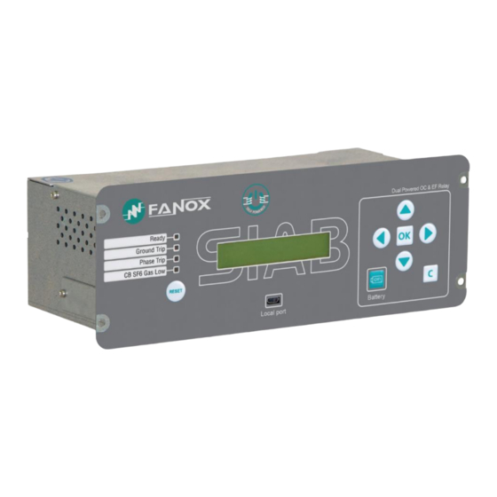
- Page 1 SIA-B Standard CT´s Self & Dual Powered Overcurrent & Earth Fault Protection Relay USER´S MANUAL EN_FANOXTD_MANU_SIA_Ocefsecondarydist_SIAB-STANDARD-CT_R007.Docx...
-
Page 2: Table Of Contents
Accumulated amps counter: I2t ..................29 4.8.4. Maximum openings in a time window ................29 4.9. Function TB. Trip block protection for the switchgear ............30 4.10. Function 46. Negative sequence inverse time overcurrent..........30 www.fanox.com Rev. 07 2/138... - Page 3 Standards ..........................76 COMMUNICATION AND HMI ....................78 7.1. Front Communication: USB ....................78 7.2. Rear communication: RS485 ....................78 7.3. LED indicators ........................79 7.4. LCD and keypad ........................79 7.5. SICom Communications program ..................79 www.fanox.com Rev. 07 3/138...
- Page 4 9.1. Identification ......................... 132 9.2. Checks ........................... 132 9.3. Test menu ..........................132 9.4. Register of commissioning settings .................. 133 9.5. Inputs ............................. 135 9.6. Outputs ..........................135 9.7. Leds ............................135 9.8. Comments ..........................136 www.fanox.com Rev. 07 4/138...
-
Page 5: Reception, Handling & Installation
It is necessary to inspect the relay at the time it is delivered to ensure that the relays have not been damaged during transport. If any defect is found, the transport company and FANOX should be informed immediately. If the relays are not for immediate use, they should be returned to their original packaging. -
Page 6: Installation, Commissioning And Service
This product must be disposed of in a safe way. It should not be incinerated or brought into contact with water sources like rivers, lakes, etc. www.fanox.com Rev. 07 6/138... -
Page 7: Dimensions And Connection Diagrams
DIMENSIONS AND CONNECTION DIAGRAMS 2.1. Front view 2.2. Case dimensions The dimensions are in mm: www.fanox.com Rev. 07 7/138... -
Page 8: Striker Dimensions
Cut-out pattern 2.3. Striker dimensions 2.3.1. PRT-15 www.fanox.com Rev. 07 8/138... -
Page 9: Prt
2.3.2. 44,5 49,5 56,5 64,5 42,5 www.fanox.com Rev. 07 9/138... -
Page 10: Connection Diagram
2.4. Connection diagram NOTE! STRIKER: 6 – 24 Vdc & <= 0.135 W·s www.fanox.com Rev. 07 10/138... -
Page 11: Terminals
Digital 3 common output Auxiliary power supply - Digital output 3 NC Common of the Inputs Digital output 3 NO Input 1 RS485 Remote communication (*) B18-B19 Input 2 Input 3 (*) Optional depending on model www.fanox.com Rev. 07 11/138... -
Page 12: Description
Worldwide, the energy sector is currently undergoing a profound change as a result of high levels of energy demand; more distribution lines and advanced supervision systems are required. Given the need for creating intelligent infrastructure, FANOX has developed the SIA family of products to carry out this function. - Page 13 The relay has a frontal communication port (micro USB). This port allows a PC to be connected, which can be used to monitor the relay using the SICom communications program (supplied by FANOX). Besides, the frontal port can be used to power the relay by using an USB cable which can be directly connected with PC.
- Page 14 Self-powering with standard CTs: ✓ 75 mA three phase/100 mA two phase/160 mA single phase Auxiliary power: 24-230 Vdc / Vac, 50/60 Hz Optional ✓ Internal commissioning battery ✓ Battery power accessory: 5 V with Kitcom adaptor www.fanox.com Rev. 07 14/138...
-
Page 15: Functional Diagram
Fault reports registered in the FRAM are maintained when there is a power fault, as it is a non-volatile memory. A maximum of 20 fault reports and 10 records in COMTRADE format can be stored. 3.3. Functional Diagram www.fanox.com Rev. 07 15/138... -
Page 16: Selection & Ordering Codes
4 LEDs + Trip (striker) + 3 Outputs + 3 Inputs Mechanics Extended Horizontal Assembly Languages English, Spanish and German English, Spanish and Turkish English, Spanish and French English, Spanish and Russian Adaptation Standard CTs /1 www.fanox.com Rev. 07 16/138... -
Page 17: Phase Ct And Neutral Ct Selection
Load Curve for SIA-B /1 relay 6,000 5,000 4,000 3,000 2,000 1,000 0,000 0,000 1,000 2,000 3,000 4,000 5,000 6,000 7,000 8,000 9,000 10,000 11,000 12,000 13,000 14,000 15,000 16,000 17,000 18,000 19,000 20,000 21,000 Average Current (A) www.fanox.com Rev. 07 17/138... -
Page 18: Burden Curve For Sia-B Relay
Impedance curve for SIA-B relay Impedance Curve for SIA-B /1 relay 10,000 1,000 0,100 0,000 1,000 2,000 3,000 4,000 5,000 6,000 7,000 8,000 9,000 10,000 11,000 12,000 13,000 14,000 15,000 16,000 17,000 18,000 19,000 20,000 Average Current (A) www.fanox.com Rev. 07 18/138... -
Page 19: Protection Functions
The serial number is only a reading setting. The rest of the settings can be changed either from the HMI or through communications. Any change of set values will restart all functions, irrespective they are activated or not. www.fanox.com Rev. 07 19/138... -
Page 20: Function Shb. Second Harmonic Blocking
±30 ms or ±0.5% (whichever is greater). If the Function Enable is set to “SHB”, the accuracy of the Time Delay is equal to the pre-set time ±50 ms or ±0.5% (whichever is greater). The function activates at 100% of the pre-set input and deactivates at 95%. The reset is instantaneous. www.fanox.com Rev. 07 20/138... -
Page 21: Function 50/51. Inverse Time Phase Overcurrent
This protection function can be set by using three parameters: Function Description Minimum Maximum Step Unit Default 50G_1 Instantaneous neutral overcurrent 50G_2 (*) Function Enable Yes/No/SHB Current Tap 0.05 10.00 0.01 5.00 Time Delay 0.02 300.00 0.01 (*) Optional depending on model www.fanox.com Rev. 07 21/138... -
Page 22: Function 50/51G. Inverse Time Neutral Overcurrent
±5% (whichever is greater). In this case, the function is activated at 110% of the set tap value, and it deactivates at 100%. Instantaneous reset in both cases. The curves used are IEC 60255-151 and IEEE, which are described in their section. www.fanox.com Rev. 07 22/138... -
Page 23: Function 49. Thermal Image Protection
This protection function is adjusted by setting five different parameters: Function Description Minimum Maximum Pitch Unit Default Thermal image protection function Function Enable Yes/No Current Tap 0.10 2.40 0.01 x In ζ heating ζ cooling ζ heating Alarm www.fanox.com Rev. 07 23/138... - Page 24 Thermal image is stored in non-volatile RAM memory periodically. By this way, though the relay loses the power supply, it will keep the thermal state of the machine. 4.7.3. Thermal image measurement display. Reset Thermal image measurement can be displayed on Measurement menu. www.fanox.com Rev. 07 24/138...
- Page 25 4.7.4. Thermal protection curves This is the thermal curve for ζ = 3 minutes. www.fanox.com Rev. 07 25/138...
-
Page 26: Function 52. Circuit Breaker Monitoring
Activated if the accumulated amps counter exceeds “Maximum accumulated (l2t) amps accumulated amps” setting exceeded Activated the number of openings exceeds the setting in “Maximum repeated openings” for the time set in “Time of maximum repeated Repeated Trips openings” www.fanox.com Rev. 07 26/138... - Page 27 52a contact to the “52a” logic signal, and the circuit breaker 52b contact to the “52b” logic signal. The circuit breakers automaton is considered as having eight statuses: Start, open, closed, error, opening time, opening error, closing time and closing error. The circuit breaker performance is shown in the following finite state machine: www.fanox.com Rev. 07 27/138...
- Page 28 Rev. 07 28/138...
-
Page 29: Circuit Breaker Opening And Closing Commands
Both parameters can be adjusted. When this number is exceeded, the “Repeated Trips” status is activated and its corresponding event is generated. This alarm resets itself, when the corresponding time is exceeded with less trips than those indicated. www.fanox.com Rev. 07 29/138... -
Page 30: Function Tb. Trip Block Protection For The Switchgear
±5% (whichever is greater). In this case, the function is activated at 110% of the set tap value, and it deactivates at 100%. Instantaneous reset in both cases. The curves used are IEC 60255-151 and IEEE, which are described in their section. www.fanox.com Rev. 07 30/138... -
Page 31: Function 50Bf. Breaker Failure Monitoring
To monitor the circuit breaker opening the current measurement via the three phases is used. When the current via the three phases is less than 60mA, the circuit breaker is considered to be open. The start of 50BF function is associated to the general trip. www.fanox.com Rev. 07 31/138... -
Page 32: Function Clp. Cold Load Pickup
“Cold load time” starts to count. During this time the relay will work with the new setting group regardless of the circuit breaker situation, this is, without considering whether the circuit breaker is maintained closed or is open. www.fanox.com Rev. 07 32/138... -
Page 33: Function 49T. External Trip
Regarding other options, regardless of that established by the settings, the inputs prevail over the settings. If the use of both inputs is not required, then one can be used, but depending on which is used, operation can be done with Setting group 1 or Setting group 2. www.fanox.com Rev. 07 33/138... -
Page 34: Iec60255-151 Curves
Ext. Inverse Very Inverse 13,5 Inverse 0,14 0,02 The curve can mode from its axis using the D time selection device, which the user can adjust. is the initial operating current, set by the user. adjusted www.fanox.com Rev. 07 34/138... - Page 35 Rev. 07 35/138...
- Page 36 Rev. 07 36/138...
- Page 37 Rev. 07 37/138...
- Page 38 Rev. 07 38/138...
-
Page 39: Ieee Curves
Very Inverse 19,61 0,491 Inverse 0,0515 0,02 0,114 The curve can move from its axis using the TD time selection device, which the user can adjust. is the initial operating current, set by the user. adjusted www.fanox.com Rev. 07 39/138... - Page 40 Rev. 07 40/138...
- Page 41 Rev. 07 41/138...
- Page 42 Rev. 07 42/138...
-
Page 43: Monitoring And Control
Sampling rate (interval): configurable through communications: 1 – 60 min • Record format: Date/Time IMAX (in interval) IMAX (actual) 5.3. Counters The following counters are provided: Number of openings of the circuit breaker Accumulated amperes (l2t) during the openings of the circuit breaker www.fanox.com Rev. 07 43/138... -
Page 44: States And Events
“delete events” option. To delete the events, it is necessary to enter a password. Events have the following structure: Identify Unique event identifier: e.g.: 51_1.4 = 51 START UP Value ON(Activated) /OFF(Deactivated): an event is generated for activations and deactivations Associate Depending of the event measurement Date Day/Month/Year Hour:Minutes:Seconds:Milliseconds www.fanox.com Rev. 07 44/138... - Page 45 EEPROM changed Activation Events error Events error Activation/Deactivation Reset Reset Activation Pickup Pickup Phase A Pickup Phase B Pickup Phase C Ground pickup Trip Phase A Trip Phase B Trip Phase C Ground trip 50 Trip www.fanox.com Rev. 07 45/138...
- Page 46 Activation/Deactivation Phase B current 50/51 50/51 Phase C pick-up 50/51 Phase C pick-up Activation/Deactivation Phase C current 50/51 Pick-up 50/51 Pick-up Activation/Deactivation Maximum current 50/51 Phase A Trip 50/51 Phase A Trip Activation Phase A current www.fanox.com Rev. 07 46/138...
- Page 47 52 Max. Accumulated 52 Max. Accumulated Activation/Deactivation amperes (I2t). amperes (I2t). 52 Max. openings/Time 52 Max. openings/Time Activation/Deactivation Negative Sequence Overcurrent (*) 46 pickup 46 pickup Activation/Deactivation Negative sequence current 46 Trip 46 Trip Activation/Deactivation Negative sequence current www.fanox.com Rev. 07 47/138...
- Page 48 Input 1 Activation/Deactivation Input 2 Input 2 Activation/Deactivation Input 3 Input 3 Outputs Trip Output Trip Output Activation/Deactivation Output 1 (*) Output 1 Activation Output 2 (*) Output 2 Activation Output 3 (*) Output 3 Activation www.fanox.com Rev. 07 48/138...
- Page 49 Remote communication (*) Remote communication Open Breaker Open Breaker Activation 2 (Command identifier) Close Breaker Close Breaker Activation 3 (Command identifier) Reset thermal image Reset thermal image Activation 10 (Command identifier) (*) Optional depending on model www.fanox.com Rev. 07 49/138...
-
Page 50: Date And Time By Real Time Clock (Rtc)
Setting group, but not with two damaged Setting groups. • There is a Watchdog device both between and in main CPUs. If any CPU goes out of operation the relay will be reset and this condition will be identified as an event. www.fanox.com Rev. 07 50/138... -
Page 51: Disturbance Fault Recording
2 situations appear on the main screen (EEPROM ERROR or EVENTS ERROR), the relay should be replaced, and it will be necessary to contact Fanox. On the other hand, “Default settings” means that the relay is operating under factory settings, being all protection functions disabled. - Page 52 COMTRADE = 33 Date/Time = 10/23/2018 - 15:47:02.584 The following information is included in each COMTRADE file: Number Analog channels Phase A current Phase B current Phase C current Neutral current This current is already in primary amps. www.fanox.com Rev. 07 52/138...
- Page 53 51G Pick-up External Trip 50BF Trip Trip Cold Load Pick-up No Trip Power Trip Output 50_1 Phase A Pick-up Phase Block Output 1 50_1 Phase B Pick-up Output 2 50_1 Phase C Pick-up Output 3 50G_1 Pick-up www.fanox.com Rev. 07 53/138...
- Page 54 It is possible to visualize the COMTRADE file using SICom software: Using SICom software, it is possible to save the COMTRADE file. www.fanox.com Rev. 07 54/138...
-
Page 55: Configurable Inputs
Output 3: it is activated when any of the ground functions trip To get the outputs to be operative it is required Single phase→270 mA or Three phases→90 mA. Once the relay detects these levels of current these outputs are instantaneously operative. www.fanox.com Rev. 07 55/138... -
Page 56: Programmable Logic Control
NOTE: As it is described above, the options NOR_LATCH, NAND_PULSES and NAND_LATCH are not available in the relay. Although, using SICOM software allows the user to configure these options, the relay will not recognize them and it will not work properly. www.fanox.com Rev. 07 56/138... - Page 57 Function 86 (latch condition) can be implemented through signaling outputs configuration. It is necessary to configure one of the signaling outputs as trip output and after this configuration if OR4_LACTH is chosen the latch of this output is being permitted. www.fanox.com Rev. 07 57/138...
-
Page 58: Leds
By default, the configuration is: OUTPUT LOGICAL GATE BINARY STATES • LED 1 Ready • Ground Trip LED 2 AND4 • General Trip LEDS • Phase Trip LED 3 AND4 • General Trip • LED 4 Input 2 www.fanox.com Rev. 07 58/138... - Page 59 Logical gate selection guide The configured signal will make a pulse of the adjusted milliseconds once the input signal is activated. Input Output The configured signal waits the adjusted milliseconds to activate itself. Input Output www.fanox.com Rev. 05 59/138...
- Page 60 The configured signal will be activated till it is externally reset (command, reset key, communications…), though the input signal drops off. Input Output The configured signal will make pulses of the adjusted milliseconds while the input signal is activated. Input Output www.fanox.com Rev. 05 60/138...
-
Page 61: Commands
NOTE: When performing the test menu, the protection will not be available, and it will be possible to open the circuit breaker. Only authorized personnel can do this job. To obtain more detailed information, the method for navigating the menus is explained graphically in the keypad and display section. www.fanox.com Rev. 07 61/138... -
Page 62: Power Supply
In a situation where the center is deenergized, if this is energized and a fault induced with the instantaneous function set at 20 ms, the trip time will be 20 ms. www.fanox.com Rev. 07 62/138... -
Page 63: Battery Power: 5 V, With A Kitcom Adaptor
The lifetime of the battery is 20 years. How to change the internal battery www.fanox.com Rev. 07 63/138... - Page 64 Unscrew the 4 screws on the front of the relay to extract it from the RMU. Access to the rear side of the relay. Unscrew the 2 screws to remove the cover from the battery compartment. www.fanox.com Rev. 07 64/138...
- Page 65 Remove the battery and replace it respecting polarity (+ facing up): Battery characteristics: AA 3.6V lithium battery Model LS14500 from SAFT Do not use rechargeable batteries or other types of battery www.fanox.com Rev. 07 65/138...
- Page 66 6. Put on the battery cover and tighten the 2 screws. 7. Put the relay into the RMU again and tighten the 4 screws on the front to fix the relay. www.fanox.com Rev. 07 66/138...
-
Page 67: Switch On To Fault (Sotf) Characteristic
The most critical case is produced when the relay is self-powered (without auxiliary voltage or battery) and low current faults. To sum up, there are a lot of factors which influence on the starting up time: self-power, auxiliary voltage, tripping time… www.fanox.com Rev. 07 67/138... - Page 68 SINGLE PHASE - 12 Vdc Time (ms) 3 PHASE - 17 Vdc Time (ms) SINGLE PHASE - 17 Vdc Time (ms) 3 PHASE - 24 Vdc Time (ms) 2375 1160 SINGLE PHASE - 24 Vdc x In www.fanox.com Rev. 07 68/138...
-
Page 69: Opening Mechanism: Striker
On the other hand, if a higher level that the required by the striker is selected, the activation of the striker is guaranteed, however, the fault trip time during start-up may be increased. Fanox encourages selecting the correct value of this critical setting and offers its expertise at any doubt. - Page 70 16 Ohm Protection class IP00 Due to the existing variety in the market, it is important to check the voltage and the necessary energy for its activation. If you have any doubt, please contact with Fanox. www.fanox.com Rev. 07 70/138...
-
Page 71: Technical Specifications And Standards
Time Delay: 0.02 to 300.00 s (step 0.01 s) Time Dial (TMS): 0.01 to 1.5 (step 0.01) Curve, activation level 110% Curve, deactivation level 100% Defined time, activation level 100% Defined time, deactivation level 95% Instantaneous deactivation www.fanox.com Rev. 07 71/138... - Page 72 Current Tap: 0.10 to 2.40 xIn (step 0.01 xIn) ζ heating: 3 to 600 minutes (step 1 min) ζ cooling: 1 a 6 x ζ heating (step 1) Alarm level: 20 a 99% (step 1 %) www.fanox.com Rev. 07 72/138...
- Page 73 With SHB permitted: ± 50 ms or ± 5% (greater of both). Timing accuracy for defined time curve selection: Without SHB permitted: ± 30 ms or ± 0.5% (greater of both). With SHB permitted: ± 50 ms or ± 0.5% (greater of both). www.fanox.com Rev. 07 73/138...
- Page 74 Load Data Profiling • Number of records: 168 (Current Demand) • Recording mode circular • Sampling rate (interval): configurable through communications: 1 – 60 • Record format: Date/Time IMAX (in interval) IMAX (actual) IA; IB; IC; IN www.fanox.com Rev. 07 74/138...
-
Page 75: Thermal Resistance
Considering that the specific CTs have a wide Is range, the thermal resistance is defined according to the minimum and maximum limit: • 4xIn continuously. • 30 x In for 10 seconds. • 100 x In for 1second. www.fanox.com Rev. 07 75/138... -
Page 76: Standards
6.3. Standards www.fanox.com Rev. 07 76/138... - Page 77 Rev. 07 77/138...
-
Page 78: Communication And Hmi
Fiber optics can be used in very aggressive environments, and they are connected by using the corresponding converters. Connection diagram for a RS485 bus: Minimum required current to achieve remote communication:360 mA (single phase), 180 mA (2- phase) and 120 mA (3-phase). www.fanox.com Rev. 07 78/138... -
Page 79: Led Indicators
Measurement reading • Reading and changing settings • Reading and changing configuration • Reading and deleting events • Reading and deleting DFR (fault reports and COMTRADE files) • Changing the user passwords • Loading settings files www.fanox.com Rev. 07 79/138... -
Page 80: How To Install Sicom Software
How to install SICOM Software 7.5.1. To install the SICom it is necessary the following link: http://fanox.blob.core.windows.net/sicom/publish.htm The link will open the next screen, where key “install” must be pressed: The necessary drivers depending on the operative system can be downloaded from this page. -
Page 81: Setting-Up The Session: Password And Access Levels
SIcom program. The password must be made up of 4 characters (passwords with more or less characters will not be accepted). By default, the relay is programmed with the following passwords and their associated levels: PASSWORD ACCESS LEVEL 2222 3333 4444 5555 www.fanox.com Rev. 07 81/138... -
Page 82: Menus
▼ are used to increase or decrease the value. If an invalid value is entered during the process, the “C” key can be used to delete it. The navigation through the menus is described as graphically as possible below. www.fanox.com Rev. 07 82/138... -
Page 83: Date-Time Menu
The contrast menu can be accessed from the standby mode screen by pressing the “◄” key. Contrast level can be changed using the “▲” and “▼” keys. Press the “C” key to return to the standby mode screen. ◄ ↑ Contrast: SIAB110FD132AC 0.00 0.00 0.00 0.00 ↓ hold www.fanox.com Rev. 07 83/138... -
Page 84: Fault Report
0.00 0.00 0.00 0.00 ↓ press 50 Trip Trip 50-1 04/11/2013 01:43:25 04/11/2018 10:43:25 Trip 51 ▲▼ 08/11/2018 17:43:25 The name of the fault reports indicates the function that has tripped and originated the fault report. www.fanox.com Rev. 07 84/138... -
Page 85: Test Menu
TEST MENU y/n? ◄ ▼ ► without protection! OK hold Set Password -> 0 Set Password ◄▼▲► -> 5555 TEST MENU Output 1: ▲▼ not activated Output 1: not activated Output 2: ▲▼ not activated Output 2: <<ACTIVATED>> www.fanox.com Rev. 07 85/138... -
Page 86: Functions Menu
<<ACTIVATED>> 7.7.9. Functions Menu The SIA-B relay menu is split up into 6 main parts: • Measurements. • States. • Settings. • Events. • Commands • LDP (Load data profiling – current demand) • Fault Reports www.fanox.com Rev. 07 86/138... - Page 87 Press the “OK” key to access the second level from the main screen. Use the ▲ and ▼ keys to move from one menu section to another in the second level. Use the “C” key to return to a higher level. www.fanox.com Rev. 07...
-
Page 88: Measurements Menu
“MEASUREMENTS” screen and press “OK”. Use the “▲” and “▼” keys to position the cursor over the measurement and to see its value. ↑ MEASUREMENTS SIAB110FD132AC 0.00 0.00 0.00 0.00 ↓ 1/10 ↑ MEASUREMENTS 0.00 A ↓ 1/10 0.00 A 2/10 ▲▼ 0.00 A 3/10 ▲▼ 0.00 A 4/10 ▲▼ 0.00 A 5/10 ▲▼ 0.00 A www.fanox.com Rev. 07 88/138... -
Page 89: States Menu
IB-2H 7/10 ▲▼ 0.00 A IC-2H 8/10 ▲▼ 0.00 A IMax 9/10 ▲▼ 0.00 A 10/10 ▲▼ 0.00 % States menu 7.7.11. ↑ STATES SIAB110FD132AC 0.00 0.00 0.00 0.00 ↓ Sta. GENERAL ↑ STATES >Activated ↓ www.fanox.com Rev. 07 89/138... - Page 90 ▲▼ not activated No Trip power: ▲▼ not activated 50 Hz: ▲▼ <<ACTIVATED>> TripBlck Enab.: ▲▼ not activated Error Measure: ▲▼ not activated Ready: ▲▼ <<ACTIVATED>> Setting change: ▲▼ Not activated Set Date/Time: ▲▼ not activated www.fanox.com Rev. 07 90/138...
- Page 91 ▲▼ not activated FactorySetting: ▲▼ not activated Error Eeprom: ▲▼ not activated Eeprom changed: ▲▼ not activated Error Event: ▲▼ not activated Pickup: ▲▼ not activated Pickup: ▲▼ not activated Phase A Pickup: ▲▼ not activated www.fanox.com Rev. 07 91/138...
- Page 92 ▲▼ not activated Phase A Trip: ▲▼ not activated Phase B Trip: ▲▼ not activated Phase C Trip: ▲▼ not activated Ground Trip: ▲▼ not activated 50 Trip: ▲▼ not activated 50G Trip: ▲▼ not activated www.fanox.com Rev. 07 92/138...
- Page 93 ▲▼ not activated Self-Power: ▲▼ not activated USB Power: ▲▼ not activated Battery: ▲▼ not activated ↑ STATES ▲▼ Sta. 50-1 ↓ Phase A Pickup: C Sta. 50-1 not activated Phase B Pickup: ▲▼ not activated www.fanox.com Rev. 07 93/138...
- Page 94 Phase B Trip: ▲▼ not activated Phase C Trip: ▲▼ not activated Phase Trip: ▲▼ not activated Sta. 50-2 ↑ STATES ▲▼ ↓ Phase A Pickup: Sta. 50-2 not activated Phase B Pickup: ▲▼ not activated www.fanox.com Rev. 07 94/138...
- Page 95 Phase A Trip: ▲▼ not activated Phase B Trip: ▲▼ not activated Phase C Trip: ▲▼ not activated Phase Trip: ▲▼ not activated ↑ STATES ▲▼ Sta. 51 ↓ Phase A Pickup: C Sta. 51 not activated www.fanox.com Rev. 07 95/138...
- Page 96 Phase A Trip: ▲▼ not activated Phase B Trip: ▲▼ not activated Phase C Trip: ▲▼ not activated Phase Trip: ▲▼ not activated ↑ STATES ▲▼ Sta. 50G-1 ↓ Ground Pickup: C Sta. 50G-1 not activated www.fanox.com Rev. 07 96/138...
- Page 97 ↑ STATES Sta. 50G-2 ▲▼ ↓ Ground Pickup: Sta. 50G-2 not activated Ground Trip: ▲▼ not activated ↑ STATES ▲▼ Sta. 51G ↓ Ground Pickup: C Sta. 51G not activated Ground Trip: ▲▼ not activated www.fanox.com Rev. 07 97/138...
- Page 98 ↑ STATES Sta. 46 ▲▼ ↓ Pickup: Sta. 46 not activated Trip: ▲▼ not activated Sta. 49 ↑ STATES ▲▼ ↓ Alarm: Sta. 49 not activated Trip: ▲▼ not activated www.fanox.com Rev. 07 98/138...
- Page 99 Phase B Block: ▲▼ not activated Phase C Block: ▲▼ not activated Phase Block: ▲▼ not activated Sta. 52 ↑ STATES ▲▼ >Activated ↓ 52 Startup: Sta. SHB not activated >Activated 52 Error: ▲▼ not activated www.fanox.com Rev. 07 99/138...
- Page 100 52 Open Error: ▲▼ not activated 52 Close: ▲▼ not activated 52 Close Time: ▲▼ not activated 52 Close Error: ▲▼ not activated Open Num.Alarm: ▲▼ not activated I2t Alarm: ▲▼ not activated Open/Time Alarm: ▲▼ not activated www.fanox.com Rev. 07 100/138...
- Page 101 CLP Disable: Sta. CLP <<ACTIVATED>> >Activated 52 Close: ▲▼ not activated 52 Open: ▲▼ not activated 52 Def. open: ▲▼ not activated Close CLP: ▲▼ not activated Open CLP: ▲▼ not activated CLP: ▲▼ not activated www.fanox.com Rev. 07 101/138...
- Page 102 Trip: ▲▼ not activated ↑ Sta. T.Block STATES ▲▼ ↓ Phase A Block: Sta. T.Block not activated Phase B Block: ▲▼ not activated Phase C Block: ▲▼ not activated Phase Block: ▲▼ not activated www.fanox.com Rev. 07 102/138...
- Page 103 C Sta. INPUTS not activated Input 2: ▲▼ not activated Input 3: ▲▼ not activated ↑ STATES ▲▼ Sta. OUTPUTS ↓ Output 1: C Sta. OUTPUTS not activated Output 2: ▲▼ not activated Output 3: ▲▼ not activated www.fanox.com Rev. 07 103/138...
- Page 104 STATES ▲▼ > Activated ↓ Led1: Sta. LEDS <<ACTIVATED>> Led2: ▲▼ not activated Led3: ▲▼ not activated Led4: ▲▼ not activated ↑ STATES ▲▼ Sta. LOGIC ↓ 52a: Sta. LOGIC not activated 52b: ▲▼ not activated www.fanox.com Rev. 07 104/138...
- Page 105 Ext Trip: ▲▼ not activated Bclk. 50/51: not activated Bclk. 50/51G: not activated SettingsG1: not activated SettingsG2: not activated Reset: not activated Logic Sig1: not activated Logic Sig2: ▲▼ not activated www.fanox.com Rev. 07 105/138...
- Page 106 Logic Sig4: not activated ↑ STATES ▲▼ Sta. LOCAL ↓ Local COM.: Sta. LOCAL not activated HMI Activity: ▲▼ <<ACTIVATED>> Open breaker: ▲▼ not activated Close Breaker: ▲▼ not activated Reset TI: ▲▼ not activated www.fanox.com Rev. 07 106/138...
- Page 107 ↑ STATES Sta. REMOTE ▲▼ ↓ Remote COM.: Sta. REMOTE not activated Open breaker: ▲▼ not activated Close Breaker: ▲▼ not activated Reset TI: ▲▼ not activated www.fanox.com Rev. 07 107/138...
-
Page 108: Settings Menu
If it is necessary to change one of the password characters or numbers due to an error, press “C” to delete it. Press “OK” to validate the password. The method for navigating through the settings menu and the sequence to follow to change a setting are shown graphically below: www.fanox.com Rev. 07 108/138... - Page 109 ▲▼ ↓ GEN ↑SETTINGS Sett(2) 50-1 COM → ↓ Function Enable Sett(2) 50-1 Set Password Function Enable -> 0 Set Password ◄▼▲► -> 5555 Function Enable NO -> NO Function Enable ▲▼ NO -> YES www.fanox.com Rev. 07 109/138...
- Page 110 NO > YES y/n SETTING CHANGED Function Enable Function Enable Current Tap ▲▼ 5.00 xIn Time Delay ▲▼ 0.2 s GEN Sett(2) 50-2 ↑SETTINGS ▲▼ COM → ↓ Function Enable Sett(2) 50-2 Current Tap ▲▼ 5.00 xIn www.fanox.com Rev. 07 110/138...
- Page 111 Function Enable Sett(2) 51 Curve type ▲▼ IEC E.I Time Dial ▲▼ 1.25 Current Tap ▲▼ 0.20 xIn Time Delay ▲▼ 0.2 s Sett(2) 50G-1 ↑ SETTINGS ▲▼ COM → ↓ Function Enable Sett(2) 50G-1 www.fanox.com Rev. 07 111/138...
- Page 112 ▲▼ COM → ↓ Function Enable Sett(2) 50G-2 Current Tap ▲▼ 5.00 xIn Time Delay ▲▼ 0.2 s Sett(2) 51G SETTINGS ↑ ▲▼ COM → ↓ Function Enable Sett(2) 51G Curve type ▲▼ IEC E.I www.fanox.com Rev. 07 112/138...
- Page 113 Time Delay ▲▼ 0.2 s Sett(2) 46 SETTINGS ↑ ▲▼ COM → ↓ Function Enable Sett(2) 46 Curve type ▲▼ IEC E.I Time Dial ▲▼ 1.25 Current Tap ▲▼ 1.00 xIn Time Delay ▲▼ 0.2 s www.fanox.com Rev. 07 113/138...
- Page 114 Current Tap ▲▼ 1.20 xIn Z Heating constant ▲▼ 3 min Cooling constant ▲▼ 1 xZ Alarm level ▲▼ 80 % Sett(2) SHB SETTINGS ↑ ▲▼ COM → ↓ Function Enable Sett(2) SHB Current Tap ▲▼ www.fanox.com Rev. 07 114/138...
- Page 115 COM → ↓ Max Num. Openings Sett(2) 52 Max Accumulated Amp ▲▼ 1000 M(A2) Max. Open Time ▲▼ 0.10 s Max. Close Time ▲▼ 0.10 s Repetitive Open Num ▲▼ Repetitiv open Time ▲▼ 9 min www.fanox.com Rev. 07 115/138...
- Page 116 15.00 s Cold Load Time ▲▼ 15.00 s Sett(2) 50BF SETTINGS ↑ ▲▼ COM → ↓ Function Enable Sett(2) 50BF Time Delay ▲▼ 0.2 s Sett(2) T. BLOCK SETTINGS ↑ ▲▼ COM → ↓ www.fanox.com Rev. 07 116/138...
- Page 117 7.00 xIn To access the general settings from the “SETTINGS” menus, press “◄” Identification SETTINGS GEN ↑ ◄ COM → Free text ↓ Frequency ▲▼ 50Hz Serial Number ▲▼ Language ▲▼ ENG. Active Settings Group ▲▼ www.fanox.com Rev. 07 117/138...
- Page 118 ▲▼ Local COM Address ▲▼ Remote COM Address ▲▼ ► To access the communication parameters from the “SETTINGS” menus, press “ ” GEN Local COM Address SETTINGS ↑ ► COM→ ↓ Remote COM Address ▲▼ www.fanox.com Rev. 07 118/138...
-
Page 119: Events Menu
4/5: ▲▼ ┐ 52 Open Error ┐ 52 Open Error Set Password EVENTS ↑ RESET -> 0 There are 5 ↓ Set Password ◄▼▲► -> 5555 Confirm Erased Events y/n? EVENTS ↑ There are 1 ↓ www.fanox.com Rev. 07 119/138... - Page 120 Position of the event within the list of events • Events generated by a state activation or reset • Associated measurement (if it has one) Associated measurement Time Date 01/01/00 00:54:18600 1/1023 Events erased Events erased Activated or Not activated Event description www.fanox.com Rev. 07 120/138...
-
Page 121: Counters Menu
0.00 0.00 0.00 0.00 ↓ Openings Number ↑COUNTERS ↓ Set Password -> 0 Openings Number Set Password ◄▼▲► -> 5555 Openings Number -> 0 Openings Number ▲▼ -> 5 Accumulated Amps Openings Number ▲▼ 0 k(A2) www.fanox.com Rev. 07 121/138... -
Page 122: Commands Menu
“OK” key to perform a command and press the “OK” key again to confirm the command. SIAB110FD132AC ↑COMMANDS 0.00 0.00 0.00 0.00 ↓ EXECUTE COMMAND y/n ↑COMMANDS Open Breaker ↓ Set Password -> 0 EXECUTE COMMAND y/n Open Breaker Set Password ◄▼▲► -> 5555 CONFIRM COMMAND y/n Open Breaker In progress www.fanox.com Rev. 07 122/138... -
Page 123: Load Data Profiling
Press “OK” and use the “▲” and “▼” keys to position the cursor over the Fault Report. It is also possible to acces fault Report menu pressing “◄” key from standby screen. SIAB110FD132AC ↑LDP 0.00 0.00 0.00 0.00 ↓ 23/10/18 17:22 ↑LDP 0.00 0.00 0.00 0.00 ↓ www.fanox.com Rev. 07 123/138... -
Page 124: Fault Reports
To delete the fault reports, position the cursor over the fault report menu and press and hold the “RESET” key, until password is requested. Introduce the password and press OK until there is a massage informing “fault reports erased”.” www.fanox.com Rev. 07... -
Page 125: Pgc And Outputs Configuration Menu
Phase A Pickup ↑Sta. 50-1 not activated ↓ Phase B Pickup Set Password ▲▼ ► not activated -> 0 Phase B Pickup not activated Set Password ◄▼▲► -> 5555 Phase B Pickup>?0 ↑Sta. 50-1 Output 1 y/n? ↓ www.fanox.com Rev. 07 125/138... - Page 126 Processing... Con ¼ Output 2 Phase B Pickup Phase B Pickup>t0 ◄ Output 2 y/n? Phase B Pickup>&0 ◄ Output 2 y/n? Phase B Pickup>§0 ◄ Output 2 y/n? Phase B Pickup>c0 ◄ Output 2 y/n? www.fanox.com Rev. 07 126/138...
- Page 127 Output 2 y/n? Phase B Pickup>p250 ◄ Output 2 y/n? Phase B Pickup>t250 ◄ Output 2 y/n? Phase B Pickup>Φ250 ◄ Output 2 y/n? Phase B Pickup>$250 Output 2 y/n? Phase B Pickup>Q250 Output 2 y/n? www.fanox.com Rev. 07 127/138...
- Page 128 Phase B Pickup>r250 Output 2 y/n? Phase B Pickup>?0 ▲▼ Output 3 y/n? Phase B Pickup>?0 ▲▼ TripOutput y/n? Phase B Pickup>?0 ► 52a y/n? Phase B Pickup>?0 ▲▼ 52b y/n? Phase B Pickup>?0 ▲▼ Ext Trip y/n? www.fanox.com Rev. 07 128/138...
- Page 129 SettingsG2 y/n? Phase B Pickup>?0 ▲▼ Reset y/n? Phase B Pickup>?0 ▲▼ Logic Sig1 y/n? Phase B Pickup>?0 ▲▼ Logic Sig2 y/n? Phase B Pickup>?0 ▲▼ Logic Sig3 y/n? Phase B Pickup>?0 ▲▼ Logic Sig4 y/n? www.fanox.com Rev. 07 129/138...
- Page 130 (up to 4). Hold the “RESET” key while viewing any of the signals associated with the output and it will be removed from the output configuration. www.fanox.com Rev. 07 130/138...
-
Page 131: Commissioning
To perform this test, connect a PC with the SICom software program to the SIA-B relay, and check that there are no communication errors. It is important to check communications port (COM) which is assign to USB. www.fanox.com Rev. 07 131/138... -
Page 132: Commissioning
• FANOX recommends the use of the KITCOM accessory with a battery in the front port. This additional energy source allows the relay to be monitored and the trip to function without the need for self-power in any breakdown situation. -
Page 133: Register Of Commissioning Settings
In Inverse Very Inverse Ext. Inverse LT Inverse IEC curve type IEEE curve type Inverse Very Inverse Ext. Inverse Def. Time Time Dial (TMS) ...……………… ……………… Time Delay www.fanox.com Rev. 07 133/138... - Page 134 In Inverse Very Inverse Ext. Inverse LT Inverse IEC curve type IEEE curve type Inverse Very Inverse Ext. Inverse Def. Time Time Dial (TMS) ...……………… ……………… Time Delay www.fanox.com Rev. 07 134/138...
-
Page 135: Inputs
Input -1: Input -2: Input -3: 9.6. Outputs Output -1: Output -2: Output -3: Trip Output: 9.7. Leds Led -1: Led -2: Led -3: Led -4: www.fanox.com Rev. 07 135/138... -
Page 136: Comments
Comments …………….....……………………………………………………………………………..… …………….....……………………………………………………………………………..… ……………....……………………………………………………………………………..…. …………….....……………………………………………………………………………..… …………….....……………………………………………………………………………..… …………….....……………………………………………………………………………..… …………….....……………………………………………………………………………..… …………….....……………………………………………………………………………..… …………….....……………………………………………………………………………..… …………….....……………………………………………………………………………..… …………….....……………………………………………………………………………..… …………….....……………………………………………………………………………..… …………….....……………………………………………………………………………..… …………….....……………………………………………………………………………..… …………….....……………………………………………………………………………..… …………….....……………………………………………………………………………..… …………….....……………………………………………………………………………..… …………….....……………………………………………………………………………..… …………….....……………………………………………………………………………..… …………….....……………………………………………………………………………..… …………….....……………………………………………………………………………..… …………….....……………………………………………………………………………..… …………….....……………………………………………………………………………..… …………….....……………………………………………………………………………..… Person in charge of commissioning………..……..…………..Date……….....… Maintenance performed on the………………….. by ………..………………………………….. www.fanox.com Rev. 07 136/138... - Page 137 NOTES: ……………………………………………………………………………………………………..… ……………………………………………………………………………………………………..… ……………………………………………………………………………………………………..… ……………………………………………………………………………………………………..… ……………………………………………………………………………………………………..… ……………………………………………………………………………………………………..… ……………………………………………………………………………………………………..… ……………………………………………………………………………………………………..… ……………………………………………………………………………………………………..… ……………………………………………………………………………………………………..… ……………………………………………………………………………………………………..… ……………………………………………………………………………………………………..… ……………………………………………………………………………………………………..… ……………………………………………………………………………………………………..… ……………………………………………………………………………………………………..… ……………………………………………………………………………………………………..… ……………………………………………………………………………………………………..… ……………………………………………………………………………………………………..… ……………………………………………………………………………………………………..… ……………………………………………………………………………………………………..… ……………………………………………………………………………………………………..… ……………………………………………………………………………………………………..… ……………………………………………………………………………………………………..… ……………………………………………………………………………………………………..… ……………………………………………………………………………………………………..… ……………………………………………………………………………………………………..… www.fanox.com Rev. 07 137/138...
- Page 138 Rev. 07 138/138...
Need help?
Do you have a question about the SIA-B Series and is the answer not in the manual?
Questions and answers