
Related Manuals for FANOX SIL-V


Summary of Contents for FANOX SIL-V
- Page 1 SIL-V Voltage, frequency and synchronism protection relay USER´S MANUAL SER´S MANUAL EN_FANOXTD_MANU_SIL_Voltagefrequency_SILV_R010.Docx...
-
Page 2: Table Of Contents
79 Autorecloser ......................... 37 4.13.1. Counter to record the number of reclosings ................. 40 4.14. Function 25. Synchronism protection function ............. 41 4.14.1. Syncronism (25) and manual closure (52) ..............43 4.14.2. Synchronism (25) and recloser (79) ................44 www.fanox.com Rev.10 2/212... - Page 3 Accessing the menus ...................... 98 7.6.4. Date-Time Menu ......................98 7.6.5. Fault report ........................99 7.6.6. Communication parameters and versions ..............99 7.6.7. Test Menu ........................100 7.6.8. Functional Menu ......................104 7.6.9. Measurements Menu ....................105 www.fanox.com Rev.10 3/212...
- Page 4 Function codes ........................ 163 8.3. Exemptions an error answers ..................164 8.4. Data type .......................... 164 8.5. Memory map of SIL-V ...................... 165 8.6. Commands map ....................... 175 8.2.5. Examples of Mosdbus frames ..................176 IEC 60870-5-103 PROTOCOL ..............177 9.1.
-
Page 5: Reception, Handling, Installation
It is necessary to inspect the equipment at the time it is delivered to ensure that the relays have not been damaged during transport. If any defect is found, the transport company and FANOX should be informed immediately. If the relays are not for immediate use, they should be returned to their original packaging. -
Page 6: Installation, Commissioning And Service
All electrical power sources should be removed before performing this operation to avoid the risk of electrical discharge. This product must be disposed of in a safe way. It should not be incinerated or brought into contact with water sources like rivers, lakes, etc… www.fanox.com Rev.10 6/212... -
Page 7: Dimensions And Connection Diagrams
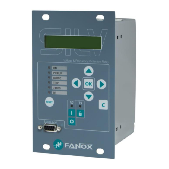
2. DIMENSIONS AND CONNECTION DIAGRAMS 2.1. Equipment front view www.fanox.com Rev.10 7/212... -
Page 8: Equipment Dimensions
2.2. Equipment dimensions www.fanox.com Rev.10 8/212... -
Page 9: Cut-Out Pattern
2.3. Cut-out pattern www.fanox.com Rev.10 9/212... -
Page 10: Connection Diagrams
2.4. Connection diagrams In SIL-V relay it is important to take into account the connection type is configurable by the user. Depending on model the following options are available: SILVxxxx0xxxxx: Using voltage transformers 3 VT configuration (phase-neutral) 3 VT configuration (phase-neutral) + residual voltage... - Page 11 3 VT configuration (phase-neutral) www.fanox.com Rev.10 11/212...
- Page 12 3 VT configuration (phase-neutral) + residual voltage (SILVxxxx0xxxxx) www.fanox.com Rev.10 12/212...
- Page 13 3 VT configuration (phase-neutral) + busbar voltage (SILVxxxx2xxxxx) www.fanox.com Rev.10 13/212...
- Page 14 3VT configuration (phase-phase) + residual voltage www.fanox.com Rev.10 14/212...
- Page 15 2VT configuration (phase-phase) + residual voltage www.fanox.com Rev.10 15/212...
- Page 16 Connecting the relay directly to Low Voltage line SILVxxxx0xxxxx and SILVxxxx2xxxxx Phase to neutral configuration (250-480 V) www.fanox.com Rev.10 16/212...
-
Page 17: Terminals
2.5. Terminals www.fanox.com Rev.10 17/212... - Page 18 (*) When the model is chosen it is very important to choose the communications protocols correctly. If “RS485” port with selectable protocol is chosen then “E” communications module is not available. If “E” communications module is chosen then “RS485” is not available. www.fanox.com Rev.10 18/212...
-
Page 19: Description
(either locally or remotely). The SIL-V equipment has 6 inputs and 4 outputs that can be set by the user: The SIL-V equipment is housed in a metal box with galvanic isolation on all of its measurement or digital inputs and outputs (with the exception of ports for communications and battery power supply, as these are sporadic connections). - Page 20 20 faults to be recorded with a capacity of 24 events per fault. In order to facilitate the analysis of events, it is fitted with oscillography records. SIL-V is fitted with 5 oscillographic registers, each one with 88 cycles (1 second at 50 Hz, 0.833 seconds at 60 Hz).
- Page 21 Automatic reconnection of the generator to the network may occur, causing damage to the generator and to the network. SIL-V protection detects this situation thanks to its voltage and frequency functions focused on the Rate of change of frequency (ROCOF) method:...
- Page 22 Function Description SIL-V Protection Synchronism 1 (Optional) ✓(2): 27P1, 27P2 Undervoltage 27V1 Positive sequence undervoltage ✓(2): 59P1, 59P2 Phase Overvoltage Negative Sequence Overvoltage ✓(2): 59N1, 59N2 Neutral overvoltage V/T Rate of change of Voltage 74TCS Trip circuit supervision Out of step (vector shift) ✓(4): 81_1, 81_2, 81_3, 81_4...
- Page 23 Function Description SIL-V Measurements Phase RMS voltages with a precision of 2% in a band ✓ of ±20% when compared to the rated voltage, and 4% in the rest of the range. (V-A, V-B, V-C) Depending on model Residual voltage (V-R) ✓...
- Page 24 Function Description SIL-V Communication ✓: 1 Local port RS232: ModBus RTU LOCAL Communication ✓ Remote ports with the following options: 1 Remote port RS485: ModBus RTU or IEC 60870-5- REMOTE Communication 103 (by general settings) 1 RJ45: IEC61850, DNP3.0 or IEC 60870-104 (depending on model) ✓...
-
Page 25: Functional Diagram
3.3. Functional Diagram www.fanox.com Rev.10 25/212... -
Page 26: Selection & Ordering Codes
3.4. Selection & Ordering codes SIL-V Protection Functions 27(2) + 27V1 + 59(2) + 47 + 59N(2) + ΔV/ΔT + 74TCS + BF + 52 + 79 + 81O/U(4) + 81R(2) + 78 + 86 Phase Measurement Defined by General settings... -
Page 27: Protection Functions
The function pick up occurs at 100% of the adjusted input and the dropout at 105%. The reset type is temporized and reset time is adjusted with reset time parameter. The accuracy of the operating time is the adjusted time ±30ms or ± 0.5% (greater of both). www.fanox.com Rev.10 27/212... -
Page 28: Function 59. Definite-Time Phase Overvoltage
The accuracy of the operating time is the adjusted time ±30ms or ± 0.5% (greater of both). NOTE: Depending on the configuration the neutral voltage can be measured or calculated: www.fanox.com Rev.10 28/212... -
Page 29: Function 47. Definite-Time Negative Sequence Overvoltage
Rate of change of voltage Permission Yes/No Type Decrement/Increment Decrement ΔV/Δt Activation level Operating time 1.00 40,00 0,01 Reset time 0,02 300.00 0,01 1,00 The accuracy of the operating time is the adjusted time ±60ms or ± 5% (greater of both). www.fanox.com Rev.10 29/212... -
Page 30: Function 81O/U. Overfrequency And Underfrecuency Protection
(1*) Overfrequency or Underfrequency The frequency measurement is an average value of the frequency measured during 8 cycles. The tripping time will be the adjusted value plus the necessary time to achieve the measure during 8 cycles www.fanox.com Rev.10 30/212... -
Page 31: Function 81R. Frequency Rate Of Change
45 volts at this stage for 78 functions to be operational. If the measured phase voltage is less than 45 volts, it activates a state bit indicating function blocked. When the frequency measurement is again valid, function begins in the start state with all bits and counters reset. www.fanox.com Rev.10 31/212... -
Page 32: Function 52. Circuit Breaker Monitoring
Maximum Step Unit Default Circuit breaker monitoring Maximum number of openings 10000 Opening time 0,02 30,0 0,01 0,10 Closing time 0,02 30,0 0,01 0,10 Maximum repeated openings 10000 Time of maximum repeated openings 1,00 300,0 0,01 9,00 www.fanox.com Rev.10 32/212... - Page 33 This physical input is then assigned to the "52a” logical signal. The 52b logical signal is calculated internally as the negative of 52a. The circuit breaker performance is shown in the following finite state machine: www.fanox.com Rev.10 33/212...
- Page 34 52a & 52b 52a & 52b 52a & 52b Fallo Fallo Cierre apertura 52a & 52b 52a & 52b TimeOut 52a & 52b 52a & 52b TimeOut 52a & 52b 52a & 52b Tiempo Tiempo apertura cierre www.fanox.com Rev.10 34/212...
-
Page 35: Circuit Breaker Opening And Closing Commands
"CONTROL" status group in the status menu. 4.10.2. Counter to register the number of openings The SIL-V equipment is fitted with a counter that registers the number of times the circuit breaker opens. This counter is associated with the "Maximum number of openings" setting. When the number of openings exceeds this preset value, the "Maximum number of openings"... -
Page 36: Bf Circuit Breaker Opening Fault
This functionality is achived through configurable digital inputs. It is verified the continuity of the coils. This function settings are as follows: Group Description Minimum Maximum Step Unit Default Trip circuit supervision 74TCS Permission Yes/No Operating time 0,02 300,00 0,01 2,00 www.fanox.com Rev.10 36/212... -
Page 37: Autorecloser
0,02 300,00 0,01 180,00 Reclose 4 time 0,02 300,00 0,01 180,00 Reclose 5 time 0,02 300,00 0,01 180,00 Hold time 0,02 300,00 0,01 10,00 Reset time 0,02 300,00 0,01 10,00 Final Opening Time 0,02 300,00 0,01 10,00 www.fanox.com Rev.10 37/212... - Page 38 It must be possible to lock the recloser, particularly is maintenance tasks are carried out on the substation. To this end there are various SIL-V locking and unlocking possibilities: • From the HMI. There is a specific key marked 79, plus a specific signal led, allowing recloser operation, locking or unlocking it.
- Page 39 Wait Reclose Condition No Hold Time Hold TimeOut Time Reclose Condition Input Close TimeOut Time 52 Close Reset TimeOut Time 52 Close & 79 Unblock Command Safety TimeOut Time LOCKOUT 52 Open 79 Block Input + 79 Block Command www.fanox.com Rev.10 39/212...
-
Page 40: Counter To Record The Number Of Reclosings
The “79 init” status is an adjustable logical signal. The “79 init” is configurable by user. The default configuration is shown below: • General trip 4.13.1. Counter to record the number of reclosings The SIL-V equipment is fitted with a counter that records the number of reclosings. www.fanox.com Rev.10 40/212... -
Page 41: Function 25. Synchronism Protection Function
8 cycles to achieve a stable measure, so the synchrocheck time should be set according to this concept. If these conditions of synchronism are mantains during synchronism time, we will have switch close permission. www.fanox.com Rev.10 41/212... - Page 42 When the voltage falls below the level of dead state, a timer is started during which we turn to undefined state until the timer ends. At this moment, indicates the dead status of the bar or line. www.fanox.com Rev.10 42/212...
-
Page 43: Syncronism (25) And Manual Closure (52)
Manual closure enable logical signalsynchronism condition or DLDB condition • Physical output (in this example output 3)Manual closure condition and recloser condition. (in this case the output 3 should be connected to the closing coil of the circuit breaker) www.fanox.com Rev.10 43/212... -
Page 44: Synchronism (25) And Recloser (79)
79 Enable logical signalSynchronism condition • A physical output (output 3 in this example)recloser closing condition and manual closing condition (in this case the output 3 should be connected to the closing coil of the circuit breaker) www.fanox.com Rev.10 44/212... -
Page 45: General Settings
These settings are defined as general because they affect the entire relay, and as a result they are not subject to a change of table. Function Description Minimum Maximum Step Unit Default General Settings “SIL-V” Equipment identifier Frequency 60/50 Serial number Language English Active table Connection type (1*) -
Page 46: Settings Table
Regarding other options, regardless of that established by the settings, the inputs prevail over the settings. If the use of both inputs is not required, then one can be used, but depending on which is used, operation can be done with table 1 or table 2. www.fanox.com Rev.10 46/212... -
Page 47: Monitoring And Control
Frequency difference between phase B line and phase B bar (depending on model) • Phase difference between phase B line voltage and busbar voltage (depending on model) In the following table the SIL-V measurement ranges are shown: Phase range Nominal voltage (phase to phase) 3 - 250 V <... -
Page 48: Statuses And Events
Eeprom changed Events error General Reset Pickup Phase A Pickup Phase B Pickup Phase C Pickup Ground Pickup Phase A Trip Phase B Trip Phase C Trip Ground Trip Phase Trip Line frequency block Bus bar frequency block www.fanox.com Rev.10 48/212... - Page 49 27_2 Phase A Pickup 27_2 Phase B Pickup 27_2 Phase C Pickup 27_2 27_2 Pickup 27_2 Phase A trip 27_2 Phase B trip 27_2 Phase C trip 27_2 Trip Positive sequence undervoltage 27V1 27V1 Pickup 27V1 Trip www.fanox.com Rev.10 49/212...
- Page 50 59_2 Phase B trip 59_2 Phase C trip 59_2 Trip Level 1 neutral instantaneous overvoltage 59N_1 59N_1 Pickup 59N_1 Trip Level 2 neutral instantaneous overvoltage 59N_2 59N_2 Pickup 59N_2 Trip Negative sequence overvoltage 47 Pickup 47 Trip www.fanox.com Rev.10 50/212...
- Page 51 Level 4: Over/Underfrequency 81O/U_4 81_4 Pickup 81_4 Trip Level 1: Frequency rate of change 81R_1 81R_1 Pickup 81R_1 Trip Level 2: Frequency rate of change 81R_2 81R_2 Pickup 81R_2 Trip Out of step (vector shift) 78 Trip www.fanox.com Rev.10 51/212...
- Page 52 Trip circuit supervision 74TCS 74TCS Pickup 74TCS Alarm Recloser 79 Standby 79 Reclosing time 79 Open 79 Hold time 79 Closing time 79 Reset time. 79 Lock out 79 Safety time 79 Final opening time 79 Enabled www.fanox.com Rev.10 52/212...
- Page 53 Digital Inputs Input 1 Input 2 Inputs Input 3 Input 4 Input 5 Input 6 Digital Outputs Output 1 Outputs Output 2 Output 3 Output 4 Leds Led-1 Led-2 Led-3 Led-4 Leds Led-5 Led-6 Led-79 Led-52 www.fanox.com Rev.10 53/212...
- Page 54 Pulse unlock 79 Continuity coil A Continuity coil B Logical signal 1 Logical signal 2 Local communication Local communication HMI Activity Open circuit breaker Close circuit breaker Local Pulse Lock 79 Pulse Unlock 79 Local control Telecontrol Reset www.fanox.com Rev.10 54/212...
- Page 55 Should it be required that a function does not generate a trip, this must be prohibited individually. In the case of the external trip input, it is sufficient to not set it. The Ready bit agglutinates correct relay operation and has the following logic: www.fanox.com Rev.10 55/212...
- Page 56 HMI, you have to go to the events menu and press and hold the "RESET" key until the number of events reads 1, and this event is registered as "Events deleted". To delete the events using communications, use the corresponding "delete events" command. www.fanox.com Rev.10 56/212...
- Page 57 Events have the following structure: Identifier Unique event identifier: e.g.: 51_1.4 = 27V1 PICKUP ON(Activated) /OFF(Deactivated): Value an event is generated for Activation and deActivation Year Month Time Minutes Seconds Milliseconds www.fanox.com Rev.10 57/212...
- Page 58 Phase Trip Activation/Deactivation Voltage Bit-29 Line frequency block Line frequency block Activation/Deactivation Voltage Bit-30 Bar ferquency block Bar ferquency block Bit-14 Fault report Activation Fault report NO. Events deleted Activation Active setting group Activation Setting group NO. www.fanox.com Rev.10 58/212...
- Page 59 27_2 Phase A trip Activation Phase A voltage Bit-09 27_2 Phase B trip 27_2 Phase B trip Activation Phase B voltage Bit-10 27_2 Phase C trip 27_2 Phase C trip Activation Phase C voltage Bit-11 27_2 Trip 27_2 Trip Activation www.fanox.com Rev.10 59/212...
- Page 60 59N_1 pickup 59N_1 pickup Activation/Deactivation Neutral voltage 59N_1 Bit-12 59N_1 Trip 59N_1 Trip Activation/Deactivation Neutral voltage Level 2 neutral instantaneous overvoltage Bit-04 59N_2 pickup 59N_2 pickup Activation/Deactivation Neutral voltage 59N_2 Bit-12 59N_2 Trip 59N_2 Trip Activation/Deactivation Neutral voltage www.fanox.com Rev.10 60/212...
- Page 61 Bit-04 81_4 Pickup 81_4 Pickup Activation/Deactivation Frequency 81O/U_4 Bit-12 81_4 Trip 81_4 Trip Activation/Deactivation Frequency Level 1: Rate of change of frequency Bit-04 81R_1 Pickup 81R_1 Pickup Activation/Deactivation Frequency 81R_1 Bit-12 81R_1 Trip 81R_1 Trip Activation/Deactivation Frequency www.fanox.com Rev.10 61/212...
- Page 62 79 Final opening time Activation Bit-09 79 Enabled Breaker failure Bit-04 BF Pickup BF Pickup Activation/Deactivation Bit-12 BF Trip BF Trip Activation/Deactivation Trip circuit supervision Bit-04 74TCS Pickup 74TCS Pickup Activation/Deactivation 74TCS Bit-12 74TCS Alarm 74TCS Alarm Activation/Deactivation www.fanox.com Rev.10 62/212...
- Page 63 LLDB: Lived line, dead bar Activation/Deactivation Bit-04 Voltage LLLB: Lived line, lived bar LLLB: Lived line, lived bar Activation/Deactivation Bit-05 Module difference Module difference Activation/Deactivation Voltage Bit-06 Frequency difference Frequency difference Activation/Deactivation Voltage Bit-07 Phase difference Phase difference Activation/Deactivation Voltage www.fanox.com Rev.10 63/212...
- Page 64 Bit-10 Output 3 Output 3 Activation/Deactivation Bit-11 Output 4 Output 4 Activation/Deactivation Leds Bit-00 Led 1 Bit-01 Led 2 Bit-02 Led 3 Bit-03 Led 4 Bit-04 Led 5 Bit-05 Led 6 Bit-06 Led 52 Bit-07 Led 79 www.fanox.com Rev.10 64/212...
- Page 65 Pulse Lock 79 Pulse Lock 79 Activation Command identifier Bit-20 Pulse Unlock 79 Pulse Unlock 79 Activation Command identifier Bit-21 Local control Local control Activation Command identifier Bit-22 Telecontrol Telecontrol Activation Command identifier Bit-23 Reset Reset Activation Command identifier www.fanox.com Rev.10 65/212...
- Page 66 Activation Bit-19 Command identifier Lock 79 Lock 79 Activation Bit-20 Command identifier Unlock 79 Unlock 79 Activation Bit-21 Command identifier Local control Local control Activation Bit-22 Command identifier Telecontrol Telecontrol Activation Bit-23 Command identifier Reset Reset Activation www.fanox.com Rev.10 66/212...
-
Page 67: Fault Reports
Local protocol. The performance is identical to the HMI, the relay synchronises the date and time and executes a new synchronisation event. Remote protocols. These protocols can include continuous synchronisation sections. For this reason, the execution of synchronisation events is inappropriate. www.fanox.com Rev.10 67/212... -
Page 68: Oscillography
5.6. Oscillography The SIL-V relay stores 5 oscillographic records, with a resolution of 16 samples/cycle and a size of 88 cycles. The first three of these cycles correspond to pre-fault. The oscillography is downloaded by communications through the front or rear port using the Modbus protocol (the protocol is documented in this manual). - Page 69 Input 4 81R_2 Pickup Input 5 27V1 Pickup Input 6 47 Pickup Output 1 dV/dt Pickup Output 2 DLDB (*) Output 3 DLLB (*) Output 4 LLDB (*) BF Pickup LLLB (*) (*) Available only in SILVxxxx2xxxxx model www.fanox.com Rev.10 69/212...
- Page 70 Analog channels = 4 Digital channels = 64 Oscillo = 1 Date/Time = 12/5/2014 - 09:52:18.570 **************************************************************** An oscillography is started when the "fault init" state is activated; this is a configurable logical signal. The default configuration is as follows: www.fanox.com Rev.10 70/212...
- Page 71 It is possible to visualize the oscillography using SICom software Using SICom software, it is possible to save the oscillo as a COMTRADE file www.fanox.com Rev.10 71/212...
-
Page 72: Configurable Inputs
5.7. Configurable Inputs The SIL-V has 6 digital inputs that can be set by the user. These inputs can be configured from the HMI, or by using the SICom program. The inputs are configured by associating the logical signals with the physical input that they require, or else no association is made if that logical signal is not in use. -
Page 73: Configurable Outputs
5.8. Configurable Outputs SIL-V is fitted with 4 digtal outputs. The outputs can be configured from the HMI or through the SICom program. The configuration of the outputs is described in point 5.9 Programmable Logic Control 5.9. Programmable Logic Control Firstly, it is defined the concept of physical input, physical output and logical signal. - Page 74 For each output there is a LOGICAL GATE. It can perform a logical operation up to 4 binary states to obtain other binary result. In V3 of the PLC the LOGICAL GATES that are supported by SIL-V are: LOGICAL GATE...
- Page 75 In the SICom the logic is as follows: Logical gate selection guide The configured signal will make a pulse of the adjusted milliseconds once the input signal is activated. Input Output The configured signal waits the adjusted milliseconds to activate itself. Input Output www.fanox.com Rev.10 75/212...
- Page 76 The configured signal will be activated till it is externally reset (command, reset key, communications…), though the input signal drops off. Input Output The configured signal will make pulses of the adjusted milliseconds while the input signal is activated. Input Output www.fanox.com Rev.10 76/212...
- Page 77 Output 1 Ready • Output 2 BF Trip • 52 manual close Output 3 PHYSICAL • 79 Closing time OUTPUTS • General trip • Local open breaker Output 4 • Remote Modbus open breaker • 60870-5-103 Open breaker www.fanox.com Rev.10 77/212...
- Page 78 General trip 79 Init 79 Enable Not configured 79 Block Not configured Lock 79 Not configured Unlock 79 Not configured • Continuity A Input-1 • Input-2 Continuity B Logical signal 1 Not configured Logical signal 2 Not configured www.fanox.com Rev.10 78/212...
-
Page 79: Function. Trip Output Lockout
OR4_LACTH General trip output will be activated and it will generate a new fault register. 5.10. 86 Function. Trip Output Lockout When the trip output is configured like OR_LACTH the programmable logic allows this output to block. www.fanox.com Rev.10 79/212... -
Page 80: Self-Diagnosis
Problem in the events recording On the other hand, a default settings error indicates that the relay is operating with default settings, whereby it will not trip (check that the relay alarm is activated with default settings). www.fanox.com Rev.10 80/212... -
Page 81: Commands
If telecontrol is used, it is recommended to configure a led to display when telecontrol is permitted and when it is not. 5.14. Date-time synchronisation The equipment can be synchronised from the HMI or by using communications. www.fanox.com Rev.10 81/212... -
Page 82: Test Program
5.15. Test program The SIL-V relay is equipped with a test menu from where the led and outputs operation can be checked. The following table shows the components that can be tested, along with their status depending on whether they are activated or deactivated:... -
Page 83: Power Supply
It is used a power supply of 24-220 Vdc/48-230 Vac. Supply from the front is designed for fine tuning, or situations where the auxiliary voltage is not guaranteed. In these cases, complete relay operation is not guaranteed, particularly regarding outputs. www.fanox.com Rev.10 83/212... -
Page 84: Technical Specifications And Standard
Timing accuracy: ±30 ms or ± 0.5% (greater of both). Function permission : yes/no 59N_1 59N_2 Operating range: 6 to 999V (step 0.1 V) Operating time: 0.02 to 300 s (step 0.01 s) Reset time: 0.02 to 300 s (step 0.01 s) Activation level: 100% www.fanox.com Rev.10 84/212... - Page 85 8 cycles to achieve the frequency measurement. Function permission : yes/no 81R_1 81R_2 Type: Incremento r Decrement Level: 0.1 to 5 Hz/s (step 0.1 Hz/s) Operating time: 0.06 to 40 s (step 0.01 s) Reset level: 0.06 to 40 s (step 0.01 s) www.fanox.com Rev.10 85/212...
- Page 86 Definitive opening time: 0.02 to 300 s (step 0.01 s) Dead voltage level: 3 to 555 V (step 0.1 V) 25 (*) Live voltage level: 6 to 999 V (step 0.1 V) Voltage supervision time: 0.02 to 300 s (step 0.01 s) www.fanox.com Rev.10 86/212...
- Page 87 Phase voltages (V-A, V-B, V-C), calculated neutral voltage (3V-0), residual voltage (V-R) (*), Busbar voltage (V-BB)(*), positive sequence voltage (V-1), negative sequence voltage (V-2), Maximum voltage (Vmax) and Minimum voltage (Vmin) Measurement range: Low scale (rated voltage<250 V)3-250 V High scale (rated voltage>250V)12-1000 V www.fanox.com Rev.10 87/212...
- Page 88 Environmental Operating temperature: -10 to 70ºC conditions Storage temperature: -20 to 80 ºC Relative humidity: 95% Mechanical Metal case characteristics Panel mounting Height x Width: 177 x 107 (mm) Depth: 122.1 mm IP-54 (*) Depending on model www.fanox.com Rev.10 88/212...
-
Page 89: Standards
Short field strenght for a duration of 3s. 1000 IEC 61000-4-8 A/m. Frequency 50Hz. 1.12. 100KHz damped oscillatory IEC 61000-4-18 Class 3, Repetition frequency 40Hz, Duration waves of each application 3s. Common mode: ±2.5kV. Differential mode: ±1kV www.fanox.com Rev.10 89/212... - Page 90 4. Contact performance IEC 60255-27 Communication requirements ModBus RTU IEC 61850 IEC 60870-5-103 IEC 60870-5-104 DNP 3.0 Climatic environmental IEC 60255-27 requirements 6.1. Cold IEC 60068-2-1 Cold Operation Ab, -25ºC, 72h Cold transport & Storage Ad, -40ºC, 72h www.fanox.com Rev.10 90/212...
- Page 91 Declared on manual, without damage for overload continuous operation 8.4. VT Input short time IEC 60255-27 Declared on manual, without damage for 10s overload short time overloading 9. Enclosure protection 60255-27 IP-54 IEC 60529 Quality Management System ISO 9001:2008 www.fanox.com Rev.10 91/212...
-
Page 92: Communication And Hmi
7. COMMUNICATION AND HMI The SIL-V relay is equipped with the following communications ports: LOCAL (front) RS232 Modbus RTU REMOTE (rear) RS485 Modbus RTU or IEC 60870-5-103 (by general settings) REMOTE (rear) RJ45 IEC 61850 (Depending on model) REMOTE (rear) RJ45 DNP 3.0 (Depending on model) - Page 93 Connection diagram for a RS485 bus: SIL-V with one RJ45 port for IEC61850, DNP3.0 or IEC60870-5-104 In this case there is one RJ45 port for IEC 61850 protocol, for DNP 3.0 protocol or for IEC 60870-5-104 protocol depending on model.
-
Page 94: Lcd And Keypad
7.3. LCD and keypad The front of the SIL-V relay is fitted with an alphanumeric LCD screen, measuring 20x2. This screen provides the user with access to read information about the settings parameters, measurements, status and events. All of this information is arranged in a system of menus. -
Page 95: How To Install Sicom Software
How to install SICOM Software To install the SICom it is necessary the following link: http://fanox.blob.core.windows.net/sicom/publish.htm The link will open the next screen, where key “install” must be pressed: The necessary drivers depending on the operative system can be downloaded from this page. -
Page 96: Setting Up The Session: Password And Access Levels
SIcom program. It is possible to change the passwords The password must have 4 characters. By default, the equipment is programmed with the following passwords and their associated levels: PASSWORD ACCESS LEVEL 2222 3333 4444 5555 www.fanox.com Rev.10 96/212... -
Page 97: Menus
When a trip occurs, the default screen alternates with the last trip screen, showing the cause of the trip and the time and date of its occurrence. Trip 59-1 07/04/15 13:51:44825 The last trip screen will disappear when the “RESET” button is pressed and hold down. www.fanox.com Rev.10 97/212... -
Page 98: Accessing The Menus
“OK” to change the equipment date. Press the “C” key to return to the standby mode screen. The date-time information can be viewed by pressing the “►” key from the main screen. DATE AND TIME SILV000C0A12BA 07/04/2015 11:43:25 0.00 0.00 0.00 0.00 ↓ 07/04/2015 11:43 www.fanox.com Rev.10 98/212... -
Page 99: Fault Report
LOCAL COM Settings SILV000C0A12BA 19200-8-N-1 0.00 0.00 0.00 0.00 LOCAL Settings ▼ 19200-8-N-1 REMOTE COM Settings ▼ (*) REMOTE COM parameters depend on model ( the used protocol can be IEC61850, DNP3.0, IEC60870-5-104, Modbus or IEC60870-5-103 depending on model) www.fanox.com Rev.10 99/212... -
Page 100: Test Menu
0.00 0.00 ◄ ▼ ► OK HOLD Set Password SILV000C0A12BA -> 0 0.00 0.00 0.00 0.00 Set Password ◄▼▲► -> 5555 SILV000C0A12BA TEST MENU 0.00 0.00 0.00 0.00 Led-1: not activated Led-1: <<ACTIVATED>> Led-2: ▲▼ not activated www.fanox.com Rev.10 100/212... - Page 101 Led-2: <<ACTIVATED>> Led-3: ▲▼ not activated Led-3: <<ACTIVATED>> Led-4: ▲▼ not activated Led-4: <<ACTIVATED>> Led-5: ▲▼ not activated Led-5: <<ACTIVATED>> Led-6: not activated Led-6: <<ACTIVATED>> www.fanox.com Rev.10 101/212...
- Page 102 Led-79: ▲▼ not activated Led-79: <<ACTIVATED>> Led-52: ▲▼ not activated Led-52: <<ACTIVATED>> Output 1: ▲▼ not activated Output 1: <<ACTIVATED>> Output 2: ▲▼ not activated Output 2: <<ACTIVATED>> www.fanox.com Rev.10 102/212...
- Page 103 Output 4: ▲▼ not activated Output 4: <<ACTIVATED>> NOTE : Be careful when activating the output which is set to trip. When the equipment is installed it will open the circuit as if it were a trip. www.fanox.com Rev.10 103/212...
-
Page 104: Functional Menu
7.6.8. Functional Menu The SIL-V relay menu is split up into 6 main parts: • Measurements. • Status. • Settings. • Events. • Counters. • Commands. • Fault report SILV000C0A12BA MEASUREMENTS SILV000C0A12BA 0.00 0.00 0.00 0.00 0.00 0.00 0.00 0.00 STATES ▲▼... -
Page 105: Measurements Menu
“MEASUREMENTS” screen and press “OK”. Use the “▲” and “▼” keys to position the cursor over the measurement and to see its value. ↑ MEASUREMENTS SILV000C0A12BA 0.00 0.00 0.00 0.00 ↓ ↑ 1/17 MEASUREMENTS 0.00 A ↓ 1/17 0.00 A 2/17 ▲▼ 0.00 A 3/17 ▲▼ 0.00 A www.fanox.com Rev.10 105/212... - Page 106 0.00 A 6/17 ▲▼ 0.00 A 7/17 ▲▼ 0.00 A VMin 8/17 ▲▼ 0.00 A VMax 9/17 ▲▼ 0.00 A dVA/dt 10/17 ▲▼ 0.00 A dVB/dt 11/17 ▲▼ 0.00 A dVC/dt 12/17 ▲▼ 0.00 A www.fanox.com Rev.10 106/212...
- Page 107 13/17 0.00 A Lin.Frq 14/17 ▲▼ 0.00 A Bar Frq 15/17 0.00 A Frq.Diff 16/17 ▲▼ Phs.Diff 17/17 www.fanox.com Rev.10 107/212...
-
Page 108: States Menu
There is a quick way to access the GNAL Statuses from the SIL-V relay main screen. Press the ◄ key to jump directly to the third level of the menu; this takes the user directly from the main screen to the GNAL Statuses option. - Page 109 Set Date/Time: ▲▼ not activated Local Ctrl.: ▲▼ not activated FactorySetting: ▲▼ not activated Eeprom error: ▲▼ not activated Eeprom changed: ▲▼ not activated Event error: ▲▼ not activated Reset: ▲▼ not activated Pickup: ▲▼ not activated www.fanox.com Rev.10 109/212...
- Page 110 Phase C pickup: ▲▼ not activated Ground pickup: ▲▼ not activated Phase A Trip: ▲▼ not activated Phase B Trip: ▲▼ not activated Phase C Trip: ▲▼ not activated Ground Trip: ▲▼ not activated Phase Trip: ▲▼ not activated www.fanox.com Rev.10 110/212...
- Page 111 ↓ Phase A Pickup Sta. 27-1 not activated Phase B Pickup: ▲▼ not activated Phase C Pickup: ▲▼ not activated Phase Pickup: ▲▼ not activated Phase A Trip: ▲▼ not activated Phase B Trip: ▲▼ not activated www.fanox.com Rev.10 111/212...
- Page 112 ↑ STATES Sta. 27-2 ▲▼ ↓ Phase A Pickup: Sta. 27-2 not activated Phase B Pickup: ▲▼ not activated Phase C Pickup: ▲▼ not activated Phase Pickup: ▲▼ not activated Phase A Trip: ▲▼ not activated www.fanox.com Rev.10 112/212...
- Page 113 Phase C Trip: ▲▼ not activated Phase Trip: ▲▼ not activated Sta. 27V1 ↑ STATES ▲▼ ↓ Pickup: Sta. 27V1 not activated Trip: ▲▼ not activated ↑ Sta. 59-1 STATES ▲▼ ↓ Phase A Pickup: Sta. 59-1 not activated www.fanox.com Rev.10 113/212...
- Page 114 Phase A Trip: ▲▼ not activated Phase B Trip: ▲▼ not activated Phase C Trip: ▲▼ not activated Phase Trip: ▲▼ not activated Sta. 59-2 ↑ STATES ▲▼ ↓ Phase A Pickup: Sta. 59-2 not activated www.fanox.com Rev.10 114/212...
- Page 115 Phase C Pickup: not activated Phase Pickup: not activated Phase A Trip: ▲▼ not activated Phase B Trip: ▲▼ not activated Phase C Trip: ▲▼ not activated Phase Trip: ▲▼ not activated ↑ Sta. 59N-1 STATES ▲▼ ↓ www.fanox.com Rev.10 115/212...
- Page 116 Trip: ▲▼ not activated Sta. 59N-2 ↑ STATES ▲▼ ↓ Pickup: Sta. 59N-2 not activated Trip: ▲▼ not activated ↑ STATES Sta. 47 ↓ Pickup: Sta. 47 not activated Trip: not activated Sta. ΔV/Δt ↑ STATES ↓ www.fanox.com Rev.10 116/212...
- Page 117 Phase C Pickup: not activated ▲▼ Phase Pickup: not activated ▲▼ Phase A Trip: not activated ▲▼ Phase B Trip: not activated ▲▼ Phase C Trip: not activated ▲▼ Phase Trip: not activated ▲▼ ↑ Sta. 81-1 STATES ↓ www.fanox.com Rev.10 117/212...
- Page 118 Trip: not activated ▲▼ ↑ STATES Sta. 81-2 ↓ Pickup: Sta. 81-2 not activated Trip: not activated ▲▼ Sta. 81-3 ↑ STATES ↓ Pickup: Sta. 81-4 not activated Trip: not activated ▲▼ Sta. 81-4 ↑ STATES ↓ www.fanox.com Rev.10 118/212...
- Page 119 Trip: not activated ▲▼ ↑ STATES Sta. 81R-1 ↓ Pickup: Sta. 81R-1 not activated Trip: not activated ▲▼ Sta. 81R-2 ↑ STATES ↓ Pickup: Sta. 81R-2 not activated Trip: not activated ▲▼ ↑ Sta. 78 STATES ↓ www.fanox.com Rev.10 119/212...
- Page 120 ↓ Pickup: Sta. 74TCS not activated Alarm: not activated ▲▼ ↑ STATES Sta. BF ↓ Pickup: Sta. BF not activated Trip: not activated ▲▼ ↑ Sta. 79 STATES ▲▼ >Lockout ↓ Standby: Sta. 79 not activated >Lockout www.fanox.com Rev.10 120/212...
- Page 121 79 Hold Time: ▲▼ not activated 79 Close Time: ▲▼ not activated 79 Reset Time: ▲▼ not activated 79 Lockout: ▲▼ not activated 79 Security T.: ▲▼ not activated 79 Manual Open: ▲▼ not activated www.fanox.com Rev.10 121/212...
- Page 122 52 Error: ▲▼ not activated 52 Open: ▲▼ not activated 52 Open Time: ▲▼ not activated 52 Open Error: ▲▼ <<ACTIVATED>> 52 Close: ▲▼ not activated 52 Close Time: ▲▼ not activated 52 Close Error: ▲▼ not activated www.fanox.com Rev.10 122/212...
- Page 123 <<ACTIVATED>> Too Many Trips: ▲▼ not activated 52A contact: ▲▼ not activated 52B contact: ▲▼ not activated Manual close: ▲▼ not activated ↑ STATES Sta. 25 ▲▼ ↓ Synchrocheck: Sta. 25 not activated DLDB: ▲▼ not activated www.fanox.com Rev.10 123/212...
- Page 124 LLLB: ▲▼ not activated Module diff.: ▲▼ not activated Freq. diff.: ▲▼ not activated Phase diff.: ▲▼ not activated Sta. INPUTS ↑ STATES ↓ Input 1: Sta. INPUTS not activated Input 2: ▲▼ not activated www.fanox.com Rev.10 124/212...
- Page 125 Input 5: ▲▼ not activated Input 6: ▲▼ not activated ↑ Sta. OUTPUTS STATES >Activated ↓ Output 1: Sta. OUTPUTS <<ACTIVATED>> >Activated Output 2: ▲▼ not activated Output 3: ▲▼ not activated Output 4: ▲▼ not activated www.fanox.com Rev.10 125/212...
- Page 126 Sta. LEDS STATES >Activated ↓ Led1: Sta. LEDS <<ACTIVATED>> >Activated Led2: ▲▼ not activated Led3: ▲▼ not activated Led4: ▲▼ not activated Led5: ▲▼ not activated Led6: ▲▼ not activated Led-52: ▲▼ not activated Led-79: ▲▼ not activated www.fanox.com Rev.10 126/212...
- Page 127 >Activated 52b: ▲▼ not activated Ext Trip: ▲▼ not activated BF Init: ▲▼ not activated Fault Init: ▲▼ not activated Manual close Init: ▲▼ not activated Manual close Enable: ▲▼ not activated Reset: ▲▼ not activated www.fanox.com Rev.10 127/212...
- Page 128 79Init: ▲▼ not activated 79 Enable: ▲▼ not activated L Lock 79: ▲▼ not activated P Lock 79: ▲▼ not activated P Unlock 79: ▲▼ not activated 74TCS A: ▲▼ not activated 74TCS B: ▲▼ not activated www.fanox.com Rev.10 128/212...
- Page 129 Sta. LOCAL STATES >Activated ↓ Local COM.: Sta. LOCAL not activated >Activated HMI Activity: ▲▼ <<ACTIVATED>> Open Breaker: ▲▼ not activated Close Breaker: ▲▼ not activated P Lock 79: ▲▼ not activated P Unlck 79: ▲▼ not activated www.fanox.com Rev.10 129/212...
- Page 130 Reset: ▲▼ not activated ↑ Sta. REMOTE STATES ↓ Remote COM.: Sta. REMOTE not activated Open Breaker: ▲▼ not activated Close Breaker: ▲▼ not activated P Lock 79: ▲▼ not activated P Unlck 79: ▲▼ not activated www.fanox.com Rev.10 130/212...
- Page 131 Local Ctrl.: ▲▼ not activated Telecontrol: ▲▼ not activated Reset: ▲▼ not activated NOTE: REMOTE COM can be ModBus, IEC60870-5-103, IEC61850, DNP3.0 or IEC60870-5-104 depending on model www.fanox.com Rev.10 131/212...
-
Page 132: Settings Menu
SETTINGS GEN ↑ Select group ↑ 1 (Active group) COM " ↓ ↓ ↑ Select group ▲▼ ↓ ↑ Select group ▲▼ ↓ SETTINGS GEN Sett(1) 27-1 ↑ COM " ↓ Function Enable Sett(1) 27-1 www.fanox.com Rev.10 132/212... - Page 133 -> 0 Set Password ◄▼▲► -> 5555 Function Enable NO -> NO Function Enable ▲▼ NO -> YES Function Enable NO > YES y/n SETTING CHANGED Function Enable Function Enable ▲▼ 10.00 V Operating time ▲▼ 0.02 s www.fanox.com Rev.10 133/212...
- Page 134 COM " ↓ Function Enable Sett(1) 27-2 ▲▼ 10.00 V Operating time ▲▼ 5.00 s Reset time ▲▼ 0.20 s Sett(1) 27V1 SETTINGS GEN ↑ ▲▼ COM " ↓ Function Enable Sett(1) 27V1 ▲▼ 1.00 V www.fanox.com Rev.10 134/212...
- Page 135 0.20 s ↑ SETTINGS Sett(1) 59-1 ▲▼ COM " ↓ Function Enable Sett(1) 59-1 ▲▼ 100 V Operating time ▲▼ 1.00 s Reset time ▲▼ 0.20 s ↑ Sett(1) 59-2 SETTINGS ▲▼ COM " ↓ www.fanox.com Rev.10 135/212...
- Page 136 100 V Operating time ▲▼ 2.00 s Reset time ▲▼ 0.20 s Sett(1) 59N-1 ↑ SETTINGS ▲▼ COM " ↓ Function Enable Sett(1) 59N-1 ▲▼ 10.00 V Operating time ▲▼ 2.00 s Reset time ▲▼ 0.20 s www.fanox.com Rev.10 136/212...
- Page 137 ↑ COM " ↓ Function Enable Sett(1) 59N-2 ▲▼ 10.00 V Operating time ▲▼ 2.00 s Reset time ▲▼ 0.20 s ↑ Sett(1) 47 SETTINGS ▲▼ COM ↓ Function Enable Sett(1) 47 ▲▼ 1.00 V www.fanox.com Rev.10 137/212...
- Page 138 2.00 s Reset time ▲▼ 0.20 s ↑ Sett(1) 81-1 SETTINGS ▲▼ COM " ↓ Function Enable Sett(1) 81-1 Type ▲▼ Overfrequency Activation level ▲▼ 50 Hz Operating time ▲▼ 0.50 s Reset time ▲▼ 0.20 s www.fanox.com Rev.10 138/212...
- Page 139 COM " ↓ Function Enable Sett(1) 81-2 Type ▲▼ Overfrequency Activation level ▲▼ 50 Hz Operating time ▲▼ 0.50 s Reset time ▲▼ 0.20 s Sett(1) 81-3 ↑ SETTINGS COM " ↓ Function Enable Sett(1) 81-3 www.fanox.com Rev.10 139/212...
- Page 140 50 Hz Operating time ▲▼ 0.50 s Reset time ▲▼ 0.20 s Sett(1) 81-4 SETTINGS ↑ COM " ↓ Function Enable Sett(1) 81-4 Type ▲▼ Overfrequency Activation level ▲▼ 50 Hz Operating time ▲▼ 0.50 s www.fanox.com Rev.10 140/212...
- Page 141 Reset time ▲▼ 0.20 s Sett(1) 81R-1 ↑ SETTINGS COM " ↓ Function Enable Sett(1) 81R-1 Type ▲▼ Increase Activation level ▲▼ 1.5 Hz/s Operating time ▲▼ 0.50 s Reset time ▲▼ 0.20 s www.fanox.com Rev.10 141/212...
- Page 142 Sett(1) 81R-2 Type ▲▼ Increase Activation level ▲▼ 1.5 Hz/s Operating time ▲▼ 0.50 s Reset time ▲▼ 0.20 s Sett(1) 78 SETTINGS ↑ COM " ↓ Function Enable Sett(1) 78 Activation level ▲▼ 1 deg www.fanox.com Rev.10 142/212...
- Page 143 Sett(1) 74TCS Operating time ▲▼ 0.50 s Sett(1) BF SETTINGS ↑ COM " ↓ Function Enable Sett(1) BF Operating time ▲▼ 0.20 s Sett(1) 79 SETTINGS ↑ ▲▼ COM " ↓ Function Enable Sett(1) 79 www.fanox.com Rev.10 143/212...
- Page 144 Recloser Number ▲▼ Reclose 1 Time ▲▼ 0.02 s Reclose 2 Time ▲▼ 0.02 s Reclose 3 Time ▲▼ 1.00 s Reclose 4 Time ▲▼ 1.00 s Reclose 5 Time ▲▼ 1.00 s Hold Time ▲▼ 1.00 s www.fanox.com Rev.10 144/212...
- Page 145 COM " ↓ Max Acumulated Open Sett(1) Max. Open Time ▲▼ 0.10 s Max. Close Time ▲▼ 0.10 s Repetitive Open Num ▲▼ Repetitiv Open Time ▲▼ 9.00 min Sett(1) SETTINGS ↑ COM " ↓ ▲▼ www.fanox.com Rev.10 145/212...
- Page 146 Serial number is a read only setting. Nominal voltage can be selected from 110 volts till 480 volts. Thanks to this range it is possible to work with VT or connecting the relay directly to the line www.fanox.com Rev.10 146/212...
- Page 147 Connecting the relay directly to Low Voltage line Phase to neutral configuration (250-480 V) SILVxxxx2xxxxx: Using voltage transformers 3 VT configuration (phase-neutral) + busbar voltage Connecting the relay directly to Low Voltage line Phase to neutral configuration + busbar voltage www.fanox.com Rev.10 147/212...
- Page 148 Identification ↑ SETTINGS ◄ SIL-V COM " ↓ Frequency ▲▼ 50Hz Serial number ▲▼ Language ▲▼ ENG. VT type ▲▼ 3 P-N+Vr Nominal V. P-P ▲▼ 110 V Local COM Address ▲▼ Remote Address ▲▼ www.fanox.com Rev.10 148/212...
- Page 149 The keys ▲, ▼, ◄ and ► are used to enter the password. ▲ and ▼ are used to introduce a value or a character, and the ◄ and ► keys are used to move from one character to another. If it is necessary to change one of the password characters or numbers due to an error, press "C" to delete it. Press "OK” to validate the password. www.fanox.com Rev.10 149/212...
-
Page 150: Events Menu
4/5: 0 ▲▼ ┐ 52 Open Error ┐ 52 Open Error Set Password EVENTS ↑ RESET -> 0 There are 5 ↓ Set Password ◄▼▲► -> 5555 Confirm Erased Events y/n? EVENTS ↑ There are 1 ↓ www.fanox.com Rev.10 150/212... - Page 151 • Position of the event within the list of events • Events generated by a status activation or reset • Associated measurement (if it has one) Associated Time Event number measurement Date 01/01/00 00:54:18600 1/120 measurement EventsErased EventsErased Activated or Not activated Event Description www.fanox.com Rev.10 151/212...
-
Page 152: Counters Menu
If it is necessary to change one of the password characters or numbers due to an error, press "C" to delete it. Press "OK” to validate the password. SILV000C2101BA ↑COUNTERS 0.00 0.00 0.00 0.00 ↓ Openings Number ↑COUNTERS ↓ Reclosings Number ▲▼ www.fanox.com Rev.10 152/212... -
Page 153: Commands Menu
EXECUTE COMMAND ↑ COMMANDS Open Breaker ↓ CONFIRM COMMAND y/n EXECUTE COMMAND Open Breaker Open Breaker In progress COMMANDS ↑ ↓ EXECUTE COMMAND ↑ COMMANDS ▲▼ Close Breaker ↓ CONFIRM COMMAND y/n EXECUTE COMMAND Close Breaker Close Breaker www.fanox.com Rev.10 153/212... - Page 154 CONFIRM COMMAND y/n EXECUTE COMMAND P Lock 79 P Lock 79 In progress ↑ COMMANDS ↓ EXECUTE COMMAND ↑ COMMANDS ▲▼ P Unlck 79 ↓ CONFIRM COMMAND EXECUTE COMMAND P Unlck 79 P Unlck 79 In progress www.fanox.com Rev.10 154/212...
- Page 155 EXECUTE COMMAND ↑ COMMANDS ▲▼ Local Ctrl. ↓ CONFIRM COMMAND y/n EXECUTE COMMAND Local Ctrl. Local Ctrl. In progress ↑ COMMANDS ↓ EXECUTE COMMAND ↑ COMMANDS ▲▼ Telecontrol ↓ CONFIRM COMMAND y/n EXECUTE COMMAND Telecontrol Telecontrol In progress www.fanox.com Rev.10 155/212...
- Page 156 COMMANDS ↑ ↓ EXECUTE COMMAND ↑ COMMANDS ▲▼ Reset ↓ CONFIRM COMMAND y/n EXECUTE COMMAND Reset Reset In progress ↑ COMMANDS ↓ www.fanox.com Rev.10 156/212...
-
Page 157: Fault Report Menu
NOTE: if fault report is configured to a situation that does not cause trip screen then the fault report is identified with the number of report (example in the flowchart Fault report 77). If fault report is configured to a situation that originates a trip screen the the fault report is identified with the trip (example in the flowchart Trip 59-1) www.fanox.com Rev.10 157/212... -
Page 158: Input, Leds, Logical Signals And Physical Outputs Configuration Menu
Led 1 y/n? Phase B Pickup: Phase B Pickup: States 59-1 ▲▼ ◄ > Led 2 y/n? > Led 2 y/n? Configuration Processing... Con 1/4 Led 2 Phase B Pickup Phase B Pickup: ◄ Ю > Led 2 y/n? www.fanox.com Rev.10 158/212... - Page 159 Led 2 y/n? ◄ Phase B Pickup: § > Led 2 y/n? ◄ Phase B Pickup: > Led 2 y/n? ◄ Phase B Pickup: > Led 2 y/n? ◄ Phase B Pickup: > Led 2 y/n? ◄ www.fanox.com Rev.10 159/212...
- Page 160 Phase B Pickup: > Led 2 y/n? ◄ Phase B Pickup: > Led 2 y/n? ◄ Phase B Pickup: ▲▼ > Led 3 y/n? Phase B Pickup: > Led 4 y/n? Phase B Pickup: > Led 5 y/n? www.fanox.com Rev.10 160/212...
- Page 161 > Led-52 y/n? Phase B Pickup: > Led-79 y/n? Phase B Pickup: > Output 1 y/n? Phase B Pickup: > Output 2 y/n? Phase B Pickup: > Output 3 y/n? Phase B Pickup: > Output 4 y/n? www.fanox.com Rev.10 161/212...
-
Page 162: Modbus Rtu Protocol
• No parity • 1 stop bit. This document describes the steps to follow to read and write data on the SIL-V relay, as per the ModBUS/RTU protocol. This memory map is only valid for one piece of equipment and one version of the memory. The positions of existing objects in the memory remain fixed from one version to the next, but new objects will naturally have new addresses which will, in turn, remain fixed in future versions. -
Page 163: Modbus Package Format
Registers more settings. The registers are values of 2 bytes of length, transmitted with the most important byte at first. The maximum number of register to be written in a package is 60. www.fanox.com Rev.10 163/212... -
Page 164: Exemptions An Error Answers
Integer without sign of 4 bytes DWORD Integer with sign of 4 bytes Number in floating decimal point “Float” of 4 bytes FLOAT String: In length variable character chain. Final of String marked with ‘\0’. ASCIIxx xx/2 E. g.: “ABC” 0x41x42x43x00..www.fanox.com Rev.10 164/212... -
Page 165: Memory Map Of Sil-V
Criteria-30(UINT). When the data format takes up more than one BYTE, the most important BYTE is sent through the communications first, and the least important BYTE is sent last. 8.5. Memory map of SIL-V Start Number of Function... - Page 166 Delete All Events dummy 03 and 16 Events number General states in status and State reading BIT32 events section State reading Local communication in status BIT32 and events section State reading Inputs in status and events BIT32 section www.fanox.com Rev.10 166/212...
- Page 167 State reading 81-3 in status and events BIT32 section State reading 81-4 in status and events BIT32 section State reading 81R-1 in status and events BIT32 section State reading 81R-2 in status and events BIT32 section www.fanox.com Rev.10 167/212...
- Page 168 52 Max opening time 03 and 16 Setting FLOAT 52 Max closing time 03 and 16 Setting LONG 52 Excess openings number 03 and 16 Setting FLOAT 52 Excess openings time 03 and 16 Setting DENUM NO SI 79 Permission www.fanox.com Rev.10 168/212...
- Page 169 03 and 16 Setting FLOAT 59-2 Tap 03 and 16 Setting FLOAT 59-2 Operating time 03 and 16 Setting FLOAT 59-2 Reset time 03 and 16 Setting DENUM NO/YES 81-1 Permission DENUM Setting 03 and 16 81-1 Type UNDER/OVER www.fanox.com Rev.10 169/212...
- Page 170 81R-2 Type 03 and 16 DEC/INC 03 and 16 Setting FLOAT 81R-2 Tap 03 and 16 Setting FLOAT 81R-2 Operation time 03 and 16 Setting FLOAT 81R-2 Reset time 03 and 16 Setting DENUM NO SI 59N-1 Permission www.fanox.com Rev.10 170/212...
- Page 171 Setting DENUM NO/YES dV/dt Type 03 and 16 Setting FLOAT dV/dt activation level 03 and 16 Setting FLOAT dV/dt Operating time 03 and 16 Setting FLOAT dV/dt reset time 03 and 16 Confirm setting ASCII20 Equipment identifier www.fanox.com Rev.10 171/212...
- Page 172 79 Reclosing 1 time Confirm setting FLOAT 79 Reclosing 2 time Confirm setting FLOAT 79 Reclosing 3 time Confirm setting FLOAT 79 Reclosing 4 time Confirm setting FLOAT 79 Reclosing 5 time Confirm setting FLOAT 79 Hold time www.fanox.com Rev.10 172/212...
- Page 173 81-1 Reset time Confirm setting 1018 DENUM NO/YES 81-2 Permission Confirm setting DENUM 1020 81-2 Type UNDER/OVER Confirm setting 1022 FLOAT 81-2 Tap Confirm setting 1024 FLOAT 81-2 Operation time Confirm setting 1026 FLOAT 81-2 Reset time www.fanox.com Rev.10 173/212...
- Page 174 59N-1 Reset time Confirm setting 1076 DENUM NO SI 59N-2 Permission Confirm setting 1078 FLOAT 59N-2 Tap Confirm setting 1080 FLOAT 59N-2 Operating time Confirm setting 1082 FLOAT 59N-2 Reset time Confirm setting 1084 DENUM NO SI 27V1 Permission www.fanox.com Rev.10 174/212...
-
Page 175: Commands Map
FLOAT dV/dt Activation level Confirm setting 1126 FLOAT dV/dt Operating time Confirm setting 1128 FLOAT dV/dt Reset time 8.6. Commands map Open Circuit breaker Close circuit breaker Pulse Lock 79 Pulse Unlock 79 Local control Telecontrol Reset www.fanox.com Rev.10 175/212... -
Page 176: Examples Of Mosdbus Frames
Number of checksum checks address function Password address address H registers L registers um L Bytes 35,35,35,35 And the SIL-V will reply OK: Number Number H Pickup L Pickup Number of L checksum checksum address function address address registers registers Bytes www.fanox.com... -
Page 177: Iec 60870-5-103 Protocol
• General Interrogation • Synchronization • Commands transmission Information in monitor direction: <1>:= time-tagged message <2>:= time-tagged message with relative time <3>:= measurands I <5>:= identification <6>:= time synchronization <8>:= general interrogation termination Information in control direction: www.fanox.com Rev.10 177/212... - Page 178 One COMMON ADDRESS OF ASDU (identical with station address) More than one COMMON ADDRESS OF ASDU GLOBAL ADDRESS Selection of standard information numbers in monitor direction Description SIL-V System functions in monitor direction <0> End of general interrogation End of GI <0>...
- Page 179 79 Status Reclose Time <17> 79 Status Open <18> 79 Status Wait Time <19> 79 Status Reset Time <20> 79 Status Security Time <21> 79 Status final open Time <24> GEN 50Hz SE,GI <26> GEN Measurement Error SE,GI www.fanox.com Rev.10 179/212...
- Page 180 <64> Continuity B logical signal SE, GI <76> Auxiliary Input 5 SE, GI <77> Auxiliary Input 6 SE, GI <92> Auxiliary output 1 SE, GI <93> Auxiliary output 2 SE, GI <94> Auxiliary output 3 SE, GI www.fanox.com Rev.10 180/212...
- Page 181 Dead Line, Dead Bus <5> Synchrocheck <15> 27 Trip P_1 <23> 27 Trip P_2 <24> 59 Start N_1 <25> 59 Trip N_1 <26> 59 Start N_2 <27> 59 Trip N_2 <31> 59 Start P_1 <35> 59 Trip P_1 www.fanox.com Rev.10 181/212...
- Page 182 <60> 81R Start_1 <61> 81R Trip_1 <62> 81R Start_2 <63> 81R Trip_2 <72> 78 Trip <3> 74TC Trip SE,GI <4> 74TC Start <6> 27V1 Start <7> 27V1 Trip <8> 47 Start <9> 47 Trip <10> DV/DT Trip www.fanox.com Rev.10 182/212...
- Page 183 SE,GI (**) Type Identification 9 : Measurands II (Measurements IL123, VL123, P, Q, f) SIL-V relay uses this type to send the value of theVL1, VL2 and VL3, the other measures remain with value 0. Each value is in the range 0 – 4095 where 4095 corresponds to 1,2*Vn e.g.
- Page 184 Selection of standard information numbers in control direction SIL-V Description System functions in control direction <0> Initiation of general interrogation Init of GI <0> Time synchronization General commands in control direction <16> Auto-recloser on (1) / off (0) ACK,NACK Generic functions in control direction Particular commands in control direction <1>...
-
Page 185: Iec 61850 Protocol
Data object, there are Data attributes that give complete information about this Data object. As example, the ground overvoltage protection unit is represented in SIL-V according IEC 61850 as the logical node PTOV, with the prefix GND and the instance 1: GNDPTOV1... - Page 186 The Data model of SIL-V according IEC 61850 is represented in the following tables: Protection: Function Logical Node Data Object Data Attribute General Start / Pick up PTRC1 general Start / pick up L1 PTRC1 phsA Start / pick up L2...
- Page 187 81_4 Trip PTOF2 general 81R_1 Start PFRC1 general 81R_1 Trip PFRC1 general 81R_2 Start PFRC2 general 81R_2 Trip PFRC2 general 81R_4 Trip PFRC4 general 81R_4 Lockout PFRC4 stVal 78_1 Start PPAM1 general 81 Lockout GGIO3 Ind24 stVal www.fanox.com Rev.10 187/212...
- Page 188 Trip I> GGIO2 Ind4 stVal Trip IN> GGIO2 Ind5 stVal CB on by AR GGIO2 Ind6 stVal 52 Status Open Failure GGIO2 Ind7 stVal 52 Status Close Failure GGIO2 Ind8 stVal Status excessive GGIO2 Ind9 stVal openinigs www.fanox.com Rev.10 188/212...
- Page 189 Ground lockout logical GGIO3 Ind1 stVal signal External trip logical signal GGIO3 Ind2 stVal Fault init logical signal GGIO3 Ind3 stVal 79 Init logical signal GGIO3 Ind4 stVal 79 Enable logical signal GGIO3 Ind5 stVal www.fanox.com Rev.10 189/212...
-
Page 190: Services
CSWI1 Oper$ctlVal 10.2. Services SIL-V disposes of the following services according IEC 61850: DATASETS A Dataset is a grouping of information from the data model of the IED: These groupings can be used by other services for the sending of information (GOOSE, RCB, BRC). - Page 191 Trips, with the name of Trips and the following data objects: Measures, with the name of Measures and the following data objects: Events, with the name of Events and the following data objects: www.fanox.com Rev.10 191/212...
- Page 192 Rev.10 192/212...
- Page 193 URCB have not this time buffer and it is not possible recovering lost or past reports. They are usually used for reporting of measures. SIL-V device is pre configured with 10 URCB associated to the Measures Dataset: 10 BRCB associated to Events Dataset and another 10 to Trips Dataset: This way, up to 10 different clients can dispose of the whole information of events and measures.
-
Page 194: Operation
SIL-V provided for this purpose. From the ICD file of SIL-V, the client device has to select a Report with the associated Dataset. This way, client will have a list of signals that will use to configure its own database. -
Page 195: Dnp 3.0 Prococol
11. DNP 3.0 PROCOCOL 11.1. Device profile document DNP V3.00 DEVICE PROFILE DOCUMENT This document must be accompanied by : Implementation Table and Point List. FANOX Electronic, S.L. Vendor Name: SIL-V Device Name: Highest DNP Level Supported: Device Function: For Requests ... - Page 196 Sometimes Configurable _______________________________________________________________________ Attach explanation: All points support the same Function Codes :Direct Operate and Direct Operate-No ACK All points support the same Control Codes : Pulse ON, Latch ON, Latch OFF, Pulse OFF and Trip-Pulse ON. www.fanox.com Rev.10 196/212...
- Page 197 32 Bits Point-by-point list attached Other Value _____________ Point-by-point list attached Sends Multi-Fragment Responses: No Yes QUICK REFERENCE FOR DNP3.0 LEVEL 2 FUNCTION CODES & QUALIFIERS Function Codes Index Qualifier Read Size Code www.fanox.com Rev.10 197/212...
-
Page 198: Implementation Table
Analog Input – All variations Assigned to 16-Bit Analog Input Class 0. Analog Change Event – All variations 6,7,8 Assigned to 16-Bit Analog Change Event with Time 129,130 Class 2. Time and Date count=1 Operating time Fine count=1 Class 0 Data www.fanox.com Rev.10 198/212... -
Page 199: Point List
Start / pick-up L3 Start / pick-up N General trip Trip L1 Trip L2 Trip L3 General start / pick-up BF Breaker failure CB 'on' by AR AR blocked CB close / open 52 Status Open Time www.fanox.com Rev.10 199/212... - Page 200 Local control local command Telecontrol local command BF Start BF Activation Live Line, Live Bus Live Line, Dead Bus Dead Line, Live Bus Dead Line, Dead Bus 74TCS Activation 74TCS Start 25 Synhrocheck 27V1 Start 27V1 Trip 47 Start www.fanox.com Rev.10 200/212...
-
Page 201: Dnp3 Protocol Settings
Full Scale Range Phase A voltage 0 to 1.2*Vnominal Volts (0 to 4095). Phase B voltage 0 to 1.2*Vnominal Volts (0 to 4095). Phase C voltage 0 to 1.2*Vnominal Volts (0 to 4095). 11.4. DNP3 protocol settings www.fanox.com Rev.10 201/212... - Page 202 Unsolicited Retry Delay: Specifies the time to delay after an unsolicited confirm timeout before retrying the unsolicited response. Unsolicited Max. Retries: How many times should this slave resend Unsols before declaring the station offline Unsolicited Offline Retry Delay: How often to retry unsolicited responses after maxRetries attempts www.fanox.com Rev.10 202/212...
-
Page 203: Appendix
Led -3: Output 3: Led -4: Output 4: Led -5: Led -6: Led -79: Led -52: 12.4. Register of commissioning settings Password: …………………………………….……………………………………………………… Identification: ……………………….……………….....……………………………….. Nominal voltage:…….………………………………………………………………………………. VT configuration type:………………………………………………………………………………. www.fanox.com Rev.10 203/212... - Page 204 Permitted Prohibited Permission …………………xIn …………s Operating time …………s Reset Time 59_2 Permitted Prohibited Permission …………………xIn …………s Operating time …………s Reset Time 59N_1 Permitted Prohibited Permission …………………xIn …………s Operating time …………s Reset Time www.fanox.com Rev.10 204/212...
- Page 205 Permission Underfrequency Overfrequency Type ………………… Hz Activation level ………………… s Operating time ………………… s Reset time 81_4 Permitted Prohibited Permission Underfrequency Overfrequency Type ………………… Hz/s Activation level ………………… s Operating time www.fanox.com Rev.10 205/212...
- Page 206 …………………… s 1st reclosure time …………………… s 2nd reclosure time …………………… s 3rd reclosure time …………………… s 4th reclosure time …………………… s 5th reclosure time …………………… s Wait time …………………… s Reset time …………………….s Definitive opening time www.fanox.com Rev.10 206/212...
-
Page 207: Inputs
Number of openings…………………… Number openings/time:………………… Time period ………………………….min 74TCS Permitted Prohibited Permission ……..… Operating time 12.5. Inputs Input -1: Input -5: Input -2: Input -6: Input -3: Input -4: www.fanox.com Rev.10 207/212... -
Page 208: Logical Signals
BF Init Fault init Close Init Close Enable Reset Setting group 1 Setting group 2 79 Init 79 Permission Level 79 Lock Pulse 79 Lock Pulse 79 unlock Continuity A Continuity B Logical signal 1 Logical signal 2 www.fanox.com Rev.10 208/212... -
Page 209: Outputs Configuration
Output 2 Output 3 Output 4 12.8. Leds configuration Leds Flashing Latch Inverted Led 1 Led 2 Led 3 Led 4 Led 5 Led 6 Led 52 Led 79 12.8.1. Leds configuration Template PICKUP CLOSE TRIP 74TCS www.fanox.com Rev.10 209/212... -
Page 210: Comments
…………….....……………………………………………………………………………..……………....……………………………………………………………………………..…………….....……………………………………………………………………………..…………….....……………………………………………………………………………..…………….....……………………………………………………………………………..…………….....……………………………………………………………………………..…………….....……………………………………………………………………………..…………….....……………………………………………………………………………..…………….....……………………………………………………………………………..…………….....……………………………………………………………………………..…………….....……………………………………………………………………………..…………….....……………………………………………………………………………..…………….....……………………………………………………………………………..…………….....……………………………………………………………………………..…………….....……………………………………………………………………………..…………….....……………………………………………………………………………..…………….....……………………………………………………………………………..…………….....……………………………………………………………………………..…………….....……………………………………………………………………………..…………….....……………………………………………………………………………..…………….....……………………………………………………………………………..…………….....……………………………………………………………………………..…………….....……………………………………………………………………………..…………….....……………………………………………………………………………..…………….....……………………………………………………………………………..…………….....……………………………………………………………………………..Person in charge of commissioning………..……..…………..Date………..Maintenance performed on the………………….. by ………..………………………………. www.fanox.com Rev.10 210/212... - Page 211 NOTES: …………………………………………………………………………………………………..…… …………………………………………………………………………………………………..…… …………………………………………………………………………………………………..…… …………………………………………………………………………………………………..…… …………………………………………………………………………………………………..…… …………………………………………………………………………………………………..…… …………………………………………………………………………………………………..…… …………………………………………………………………………………………………..…… …………………………………………………………………………………………………..…… …………………………………………………………………………………………………..…… …………………………………………………………………………………………………..…… …………………………………………………………………………………………………..…… …………………………………………………………………………………………………..…… …………………………………………………………………………………………………..…… …………………………………………………………………………………………………..…… …………………………………………………………………………………………………..…… …………………………………………………………………………………………………..…… …………………………………………………………………………………………………..…… …………………………………………………………………………………………………..…… …………………………………………………………………………………………………..…… …………………………………………………………………………………………………..…… …………………………………………………………………………………………………..…… …………………………………………………………………………………………………..…… …………………………………………………………………………………………………..…… …………………………………………………………………………………………………..…… …………………………………………………………………………………………………..…… …………………………………………………………………………………………………..…… …………………………………………………………………………………………………..…… …………………………………………………………………………………………………..…… …………………………………………………………………………………………………..…… …………………………………………………………………………………………………..…… …………………………………………………………………………………………………..…… …………………………………………………………………………………………………..…… …………………………………………………………………………………………………..…… …………………………………………………………………………………………………..…… www.fanox.com Rev.10 211/212...
- Page 212 Rev.10 212/212...
Need help?
Do you have a question about the SIL-V and is the answer not in the manual?
Questions and answers