Table of Contents
Advertisement
Quick Links
Advertisement
Table of Contents

Related Manuals for FANOX SIL B


Summary of Contents for FANOX SIL B
- Page 1 SIL B Feeder Relay USER’S MANUAL EN_FANOXTD_MANU_SIL_Feeder_SILB_R023.Docx...
-
Page 2: Table Of Contents
Function 27_1 and 27_2. Definite-time phase undervoltage ........40 4.11. Function 32. Definite-time directional overpower ............. 41 4.12. Function 81O/U. Overfrequency and underfrecuency protection ......43 4.13. Function 52. Circuit Breaker monitoring ..............44 4.13.1. Circuit Breaker opening and closing commands ............47 www.fanox.com Rev.23 2/311... - Page 3 5.17. Power Supply ......................123 TECHNICAL SPECIFICATIONS AND STANDARDS ..........124 6.1. Technical specifications .................... 124 6.2. Thermal resistence ..................... 131 6.3. Standards ........................132 COMMUNICATION AND HMI ..................136 7.1. Local communication port. RS232 ................136 www.fanox.com Rev.23 3/311...
- Page 4 8.11. Event list ........................248 8.12. Settings map ....................... 253 8.13. Examples of Modbus packets ................... 261 IEC 60870-5-103 PROTOCOL ..................262 9.1. Physical layer ......................262 9.2. Application layer ......................262 IEC 61850 PROTOCOL ....................273 www.fanox.com Rev.23 4/311...
- Page 5 Test menu ........................297 12.4. Acceptance setting log ....................297 12.5. Inputs ........................... 304 12.6. Input configuration ..................... 305 12.7. Output configuration ....................306 LED’s configuration ....................308 12.8. LED’s configuration template ................... 309 12.8.1. 12.9. Comments ........................309 www.fanox.com Rev.23 5/311...
-
Page 6: Reception, Handling, Installation
It is necessary to inspect the equipment at the time it is delivered to ensure that the relays have not been damaged during transport. If any defect is found, the transport company and FANOX should be informed immediately. If the relays are not for immediate use, they should be returned to their original packaging. -
Page 7: Installation, Commisioning And Service
This product must be disposed of in a safe way. It should not be incinerated or brought into contact with water sources like rivers, lakes, etc. www.fanox.com Rev.23 7/311... -
Page 8: Dimensions And Connection Diagrams
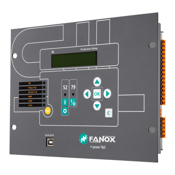
DIMENSIONS AND CONNECTION DIAGRAMS 2.1. Equipment front view www.fanox.com Rev.23 8/311... -
Page 9: Equipment Dimensions
2.2. Equipment dimensions www.fanox.com Rev.23 9/311... - Page 10 Rev.23 10/311...
-
Page 11: Cut-Out Pattern
2.3. Cut-out pattern CUT-OUT PATTERN www.fanox.com Rev.23 11/311... -
Page 12: Connection Diagrams
2.4. Connection diagrams Analog connections www.fanox.com Rev.23 12/311... - Page 13 Rev.23 13/311...
- Page 14 Digital connections Outputs and Trip circuit supervision www.fanox.com Rev.23 14/311...
-
Page 15: Terminals
2.5. Terminals IEC 61850 or DNP3.0 protocols www.fanox.com Rev.23 15/311... - Page 16 Common of digital inputs 1, 2, 3 and 4 74TCS common Digital input 5 Auxiliary voltage + Digital input 6 Auxiliary voltage - Digital input 7 IRIG B connector (depending on model) Digital input 8 Common of digital inputs 5, 6, 7 and 8 www.fanox.com Rev.23 16/311...
- Page 17 IEC 60870-5-103 protocol www.fanox.com Rev.23 17/311...
- Page 18 74TCS voltage presence Digital input 5 74TCS coil 1 Digital input 6 74TCS coil 2 Digital input 7 74TCS common Digital input 8 Auxiliary voltage + Common of digital inputs 5, 6, 7 and 8 Auxiliary voltage - www.fanox.com Rev.23 18/311...
-
Page 19: Description
The worldwide energy industry is going through a profound transformation. Due to huge energy demands, more distribution lines with advanced monitoring systems are needed. Assuming the need for creating intelligent infrastructure, FANOX has developed the SIL range of products to carry out this function. - Page 20 This is why a log of fault reports has been included. Each fault report contains up to 80 events associated with the time of failure. The log stores the reports associated with the last 20 faults that are detected. www.fanox.com Rev.23 20/311...
- Page 21 PC to be connected and the equipment to be monitored using the SICom program in Windows 7, Windows 8, Windows 8.1 or Windows 10 (supplied by FANOX). The rear communications ports are designed for different functions. One is designed for control, mainly...
- Page 22 4(depending on model) ✓ Trip Output Lockout Circuit breaker ✓ State and command of the circuit breaker ✓ Counter for the number of openings ✓ Counter for accumulated amperes ✓ Maximum number of openings in a time window www.fanox.com Rev.23 22/311...
- Page 23 Session: 4 log-in levels with a configurable password ✓ HMI: LCD, 20x2 6 keys + 1 reset button + 2 command keys for 52 + 1 separate key for ✓ locking 79 LED indicators Power Supply 24VDC-48 VDC Auxiliary voltage 90VDC–300VDC/110VAC–230VAC www.fanox.com Rev.23 23/311...
- Page 24 Depending on model ✓ Test menu ✓ Auto-diagnostic Table of settings Using keys Using inputs 3 tables of settings Using communications Cold Load Pickup Activated by current ✓ Multiplying the pickups Mechanics Dimensions 4U x ½ rack www.fanox.com Rev.23 24/311...
-
Page 25: Functional Diagram
3.3. Functional diagram www.fanox.com Rev.23 25/311... -
Page 26: Selection & Ordering Codes
USB (Modbus RTU) + RS485 (Modbus RTU) + FOC-LC (IEC 61850 HSR) Inputs and Outputs 8 Inputs + 7 Outputs Mechanics Horizontal Assembly Languages English, Spanish and German English, Spanish and Turkish English, Spanish and Russian Adaptation www.fanox.com Rev.23 26/311... -
Page 27: Phase Ct And Neutral Ct Selection
CTs and the relay must be taken into account. PRECISION BURDEN RELAYS 5P10 0,5 VA SIL-B/1 5P20 0,5 VA SIL-B/1 5P30 0,5 VA SIL-B/1 5P10 1 VA SIL-B/5 5P20 1 VA SIL-B/5 5P30 1 VA SIL-B/5 www.fanox.com Rev.23 27/311... -
Page 28: Sil-B/1 Charge Curve
3.5.1. SIL-B/1 CHARGE CURVE 3.5.2. SIL-B/5 CHARGE CURVE www.fanox.com Rev.23 28/311... -
Page 29: Protection Functions
The actuation time starts when the following conditions are met simultaneously: • Polarization voltage higher than adjusted • Phase current higher than adjusted • The phase shift of phase current and polarization voltage is such that the phase current is inside the intervention sector. www.fanox.com Rev.23 29/311... - Page 30 The actuation time is accurate to ±5%, o ±30ms, whichever is higher, of the theoretical actuation time. The curves that are used are IEC 60255-151 and IEEE, which are described in the corresponding section. The activation level for the polarization voltage is 100%, and the reset level is 95%. Resets are instantaneous. www.fanox.com Rev.23 30/311...
- Page 31 The following figure shows a graphic representation of the directional actuation zone, adjusted with an operating angle of 90° and a half-cone angle of 60°. angulo semicono = 60º Vpolarización angulo operación = 90º angulo semicono = 60º www.fanox.com Rev.23 31/311...
-
Page 32: Functions 50N/G_1 And 50N/G_2. Instantaneous Neutral Overcurrent
The actuation time starts when the following conditions are met simultaneously: • Residual voltage higher than adjusted • Residual current higher than adjusted • The phase shift of residual current and residual voltage is such that the residual current is inside the intervention sector. www.fanox.com Rev.23 32/311... - Page 33 The activation level for the residual voltage is 100%, and the reset level is 95%. Resets are instantaneous. The following figure shows a graphic representation of the directional actuation zone, adjusted with an operating angle of 90° and a half-cone angle of 60°. www.fanox.com Rev.23 33/311...
-
Page 34: Function 46. Negative Sequence Inverse-Time Overcurrent
“Operating time”. If for the curve setting it is selected a curve (inverse, very inverse or extremely inverse), operating time is function of curve settings, dial and tap. www.fanox.com Rev.23 34/311... -
Page 35: Function 49. Thermal Image Protection
As the current measurement algorithm used is r.m.s., in the thermal model is taken into account the heat produced by the harmonics. This protection function is adjusted by setting five different parameters: www.fanox.com Rev.23 35/311... -
Page 36: Thermal Image Measurement Evolution Graphic
On next graphic, thermal image measuremet evolution can be observed depending on applied current: Th % 100% alarm trip We suppose that thermal image protection has and adjusted tap of 1,1 times the nominal current and an alarm level of 75%. www.fanox.com Rev.23 36/311... -
Page 37: Thermal Image With Memory
4.6.3. Thermal image measurement display. Reset. Thermal image measuremet can be displayed on Measurement menu and Counters menu. Display is possible in Measurement menu. Display and thermal image value reset is possible in Counters menu. www.fanox.com Rev.23 37/311... -
Page 38: Thermal Protection Curves
4.6.4. Thermal protection curves This is the thermal curve for ζ = 3 minutes. www.fanox.com Rev.23 38/311... -
Page 39: Function 37_1 And 37_2. Definite-Time Phase Undercurrent
The function activates at 100% of the adjusted input and deactivates at 95%. Reset is temporized and reset time is adjusted with reset time parameter. The accuracy of the operating time is the adjusted time ±30ms. www.fanox.com Rev.23 39/311... -
Page 40: Function 59N_1 And 59N_2. Definite-Time Neutral Overvoltage
The function pick up occurs at 100% of the adjusted input and the dropout at 105%. The reset type is instantaneous temporized and reset time is adjusted with reset time parameter. The accuracy of the operating time is the adjusted time ±30ms. www.fanox.com Rev.23 40/311... -
Page 41: Function 32. Definite-Time Directional Overpower
As the characteristic angle can be adjusted from 0° to 359°, we can adjust the function to obtain direct active overpower, reverse active overpower, direct reactive overpower and reverse reactive overpower. www.fanox.com Rev.23 41/311... - Page 42 Inverse reactive overpower The following table establishes the settings for each function and its characteristics: Function Description Minimum Maximum Step Unit Default Definite-time directional overpower 32_1 32_2 Permission Yes/No 32_3 10000 32_4 Characteristic angle º Time 0.02 300.00 0.01 www.fanox.com Rev.23 42/311...
-
Page 43: Function 81O/U. Overfrequency And Underfrecuency Protection
This protection function is adjusted by setting five different parameters: Function Description Minimum Maximum Step Unit Default Overfrequency or Underfrequency 81_1 81_2 Permission Yes/No 81_3 Type (1*) Underfrequency 81_4 Activation level 45.00 65.00 0.01 Operating time 0.06 300.00 0.01 Reset time 1200.0 (1*) Overfrequency or Underfrequency www.fanox.com Rev.23 43/311... -
Page 44: Function 52. Circuit Breaker Monitoring
“Accumulated amperes counter” units are K(A²) (square kilo amperes). It is also necessary to assign the logical inputs 52a and/or 52b to a physical input. This function provides information about the circuit breaker status and if any maintenance alarm has been activated. www.fanox.com Rev.23 44/311... - Page 45 If only the circuit breaker 52a contact is available, it should be wired to the corresponding physical input. This physical input is then assigned to the "52a Input” logical input. The 52b logical input is calculated internally as the negative of 52a. The circuit breaker performance is shown in the following finite state machine: www.fanox.com Rev.23 45/311...
- Page 46 If only the circuit breaker 52b contact is available, it should be wired to the corresponding physical input. This physical input is then assigned to the "52b Input” logical input. The 52a logical input is calculated internally as the negative of 52b. The circuit breaker performance is shown in the following finite state machine: www.fanox.com Rev.23 46/311...
-
Page 47: Circuit Breaker Opening And Closing Commands
For the commands to have an effect, they should be assigned to the corresponding outputs. The "Open circuit breaker" and "Close circuit breaker" bits are assigned to their corresponding outputs in the "CONTROL" status group in the status menu. www.fanox.com Rev.23 47/311... -
Page 48: Counter To Register The Number Of Openings
When this number is exceeded, the " Excess of repetitive number of openings " status is activated and its corresponding event is generated. This alarm resets itself, when the corresponding time is exceeded with less trips than those indicated. www.fanox.com Rev.23 48/311... -
Page 49: Function 50Bf. Circuit Breaker Opening Fault
The “50BF init” status is an adjustable logic output. The default configuration is shown below: • Opening fault input activation (50BF init input) • Circuit breaker opening from an HMI/local modbus • Circuit breaker opening from a remote modbus • Circuit breaker opening from remote communications • General trip www.fanox.com Rev.23 49/311... -
Page 50: Function 74Tcs. Trip Circuit Supervision
Step Unit Default Trip circuit supervision 74TCS Permission Yes/No Time delay 0.02 300.00 0.01 2.00 The schematic for this criteria is as follows: Circuit A superv ision Circuit B superv ision Function permission Control v oltage T_UP www.fanox.com Rev.23 50/311... -
Page 51: Function 79. Autorecloser
0.02 300.00 0.01 180.00 Reclose 4 time 0.02 300.00 0.01 180.00 Reclose 5 time 0.02 300.00 0.01 180.00 Hold time 0.02 300.00 0.01 10.00 Reset time 0.02 300.00 0.01 10.00 Final Opening Time 0.02 300.00 0.01 10.00 www.fanox.com Rev.23 51/311... - Page 52 In the first four cases, the equipment stores the lock situation in the non-volatile memory, as the last control must be know for a possible re-start. The auto-recloser´s start up is shown in the following figure: There are two stable conditions here, Standby and Lockout, the other conditions are transient. www.fanox.com Rev.23 52/311...
- Page 53 Wait Reclose Condition No Hold Time Hold TimeOut Time Reclose Condition Input Close TimeOut Time 52 Close Reset TimeOut Time 52 Close & 79 Unblock Command Safety TimeOut Time LOCKOUT 52 Open 79 Block Input + 79 Block Command www.fanox.com Rev.23 53/311...
- Page 54 79TmpCierre bit The “79 Init” status is an adjustable logical output. The default configuration is shown below: • Activation of the recloser start input (“79 init input”) • 67P_1 trip • 67N_1 trip • 46 trip www.fanox.com Rev.23 54/311...
-
Page 55: Counter To Record The Number Of Reclosings
Dead line voltage 0, 1 Voltage supervision time 0.02 300.00 0.01 0.02 A time during which it is confirmed that the end is dead or live to be sure it is not a temporary situation is specified www.fanox.com Rev.23 55/311... - Page 56 Line-Bar voltage 170.0 difference Line-Bar phase ° difference 0.02 Line-Bar frequency 0.02 0,50 0.01 difference 0.02 Synchronism time 0.02 300.00 0.01 If these conditions of synchronism are mantains during synchronism time, we will have switch close permission. www.fanox.com Rev.23 56/311...
- Page 57 Line voltage and bar voltage supervision unit LLDB 25 closure permission LLDB permission DLDB DLDB permission LLLB LLLB permision | Vline | - | Vbar | < Vset | Qline- Qbar | < Qset | fline - fbar| < fset www.fanox.com Rev.23 57/311...
- Page 58 When the voltage falls below the level of dead state, a timer is started during which we turn to undefined state until the timer ends. At this moment, indicates the dead status of the bar or line. www.fanox.com Rev.23 58/311...
-
Page 59: Synchronism (25) And Recloser (79)
This is, for the recloser close is supervised by the closing permission given by sync function, it is necessary to set the "Permission of closure" state of sync function to the logical input "79 permission input". www.fanox.com Rev.23 59/311... - Page 60 If both, line and bar, are alive it will be necessary to get the reclose of the circuit breaker, not only LLLB permission to be enable either to check synchronism. If LLLB permission is enable but synchronism conditions do not verify the reclose will not occur and vice versa. www.fanox.com Rev.23 60/311...
-
Page 61: Syncronism (25) And Manual Closure (52)
For the manual closure of 52 function is supervised by the closing permission given by sync function, it is necessary to associate the "Permission of closure " status of sync function to the logical input "52 Permission of closure " www.fanox.com Rev.23 61/311... -
Page 62: Cold Load Pickup
Cold Load Pickup Permission Yes/No 50P_1 Multiplier 0.01 50P_2 Multiplier 0.01 67P_1 Multiplier 0.01 67P_2 Multiplier 0.01 50N/G_1 Multiplier 0.01 50N/G_2 Multiplier 0.01 67N_1 Multiplier 0.01 67N_2 Multiplier 0.01 CLP switch time 18000 0.01 CLP duration 18000 0.01 www.fanox.com Rev.23 62/311... - Page 63 Time to deactivate In < 10% Time Out incrementing Time Out In > 10% Cold Load Pickup In < 10% Time Out Time Out Time to activate In > 10% incrementing Time to activate decrementing In < 10% www.fanox.com Rev.23 63/311...
-
Page 64: General Settings
Function Description Minimum Maximum Step Unit Default General settings “www.fanox.com” Equipment identifier Transformation ratio of 2000 the phase CTs Transformation ratio of 2000 the neutral CTs Transformation ratio of 2000... -
Page 65: Settings Group
Regarding other options, regardless of that established by the settings, the inputs prevail over the settings. If the use of both inputs is not required, then one can be used, but depending on which is used, operation can be done with table 1 or table 2. www.fanox.com Rev.23 65/311... -
Page 66: Iec 60255-151 Curves
Parameters Ext. Inverse Very Inverse 13.5 Inverse 0.14 0.02 The curve can mode from its axis using the D time selection device, which the user can adjust. is the initial operating current, set by the user. adjusted www.fanox.com Rev.23 66/311... - Page 67 IEC Inverse 1000,000 100,000 Dial 0,05 Dial 0,1 Dial 0,2 10,000 Dial 0,3 Dial 0,4 Dial 0,5 Dial 0,6 Dial 0,7 Dial 0,8 Dial 0,9 1,000 Dial 1,0 Dial 1,1 Dial 1,2 0,100 0,010 10,0 100,0 I/It www.fanox.com Rev.23 67/311...
- Page 68 IEC Very Inverse 1000,000 100,000 Dial 0.05 Dial 0,1 10,000 Dial 0,2 Dial 0,3 Dial 0,4 Dial 0,5 Dial 0,6 Dial 0,7 1,000 Dial 0,8 Dial 0,9 0,100 0,010 10,0 100,0 I/It www.fanox.com Rev.23 68/311...
- Page 69 IEC Extremely Inverse 1000,000 100,000 Dial 0.05 Dial 10,000 Dial Dial Dial Dial Dial Dial Dial 1,000 Dial Dial Dial 0,100 0,010 10,0 100,0 I/It www.fanox.com Rev.23 69/311...
-
Page 70: Ieee Curves
0.1217 Very Inverse 19.61 0.491 Inverse 0.0515 0.02 0.114 The curve can move from its axis using the TD time selection device, which the user can adjust. is the initial operating current, set by the user. adjusted www.fanox.com Rev.23 70/311... - Page 71 IEEE Inverse 1000,000 100,000 Dial 10,000 0,05 Dial 0,1 Dial 0,2 Dial 0,5 Dial 0,8 Dial 1 Dial 1,2 1,000 0,100 0,010 10,0 100,0 I/It www.fanox.com Rev.23 71/311...
- Page 72 IEEE Very Inverse 1000,000 100,000 Dial 10,000 0,05 Dial 0,1 Dial 0,2 Dial 0,5 Dial 0,8 Dial 1 Dial 1,2 Dial 1,5 1,000 Dial 2 0,100 0,010 10,0 100,0 I/It www.fanox.com Rev.23 72/311...
- Page 73 IEEE Extremely Inverse 1000,000 100,000 Dial 0,05 10,000 Dial 0,1 Dial 0,2 Dial 0,5 Dial 0,8 Dial 1 Dial 1,2 Dial 1,5 Dial 2 1,000 Dial 2,2 0,100 0,010 10,0 100,0 I/It www.fanox.com Rev.23 73/311...
-
Page 74: Application Examples
50 function settings • Tap: 11xI • Operating time: 0.05 s 0,3500 0,3000 0,2500 0,2000 11,0000; 0,1425 0,1500 Function 51 0,1000 Function 50 0,0500 0,0000 0,0000 10,0000 20,0000 30,0000 40,0000 Figure 1. 50 y 51 IEC Inverse www.fanox.com Rev.23 74/311... - Page 75 The figure below (Figure 2), shows the tripping curve of the relay: 0,3500 0,3000 0,2500 0,2000 Function 51 0,1500 Function 50 0,1000 0,0500 11; 0,05 0,0000 0,00 4,00 8,00 12,00 16,00 20,00 24,00 28,00 32,00 Figure 2. Relay tripping curve www.fanox.com Rev.23 75/311...
- Page 76 • Dial: 2.20 • Tap: 1xI 50 function settings • Tap: 14xI • Operating time: 0.1 s 25,000 20,000 Function 51 15,000 Function 50 10,000 5,000 24; 0,376 0,000 Figure 3. 50 y 51 IEEE Extremely Inverse www.fanox.com Rev.23 76/311...
- Page 77 14xIn (50 function does not wait to reach 24xIn) The figure below (Figure 4), shows the tripping curve of the relay: 100,000 10,000 1,000 Function 51 Function 50 0,100 14; 0,1 0,010 Figure 4. Relay tripping curve www.fanox.com Rev.23 77/311...
- Page 78 Curve type: Definite time • Tap 1xIn • Operating time: 5 s 50 function settings • Tap: 15xIn • Operating time: 1 s 15; 5 Function51 as function 50 Function 50 Figure 5. Function 51 (as 50) and function 50. www.fanox.com Rev.23 78/311...
- Page 79 51 function. It is considered that this time is too high, so when current fault reaches 15xI definite time overcurrent function will be work function 50). The figure below (Figure 6), shows the tripping curve of the relay: Function 51 as function 50 Function 50 15; 1 Figure 6. Relay tripping curve www.fanox.com Rev.23 79/311...
-
Page 80: Monitoring And Control
Phase Apparent power (S-A, S-B, S-C) • Power factor (cos Phi) • Each phase Power factor (cos Phi-A, cos Phi-B, cos Phi-C) • Thermal image • Line frequency and Busbar frequency • Phase difference between phase B line voltage and busbar voltage www.fanox.com Rev.23 80/311... -
Page 81: Counters
6. Amperes accumulated (l2t) during the openings of the circuit breaker 7. Number of shots 8. Thermal Image It is possible to change tha values of the counters to a certain value, but firstly it is necessary to insert the correct password. www.fanox.com Rev.23 81/311... -
Page 82: Statuses And Events
5.3. Statuses and Events Statuses are real time information generated by the equipment. Some statuses are defined as a level, and others, like trips, are too brief to be displayed in real time. www.fanox.com Rev.23 82/311... - Page 83 67P_1 Phase B pickup 67P_1 Phase C pickup 67P_1 pickup 67P_1 Phase A trip 67P_1 Phase B trip 67P_1 Phase C trip 67P_1 Trip Level 2: Phase Inverse-time directional overcurrent 67P_2 67P_2 Phase A pickup 67P_2 Phase B pickup www.fanox.com Rev.23 83/311...
- Page 84 46 Pickup 46 Trip Thermal image protection 49 Alarm 49 Trip Level1: Definite time undercurrent 37P_1 37P_1 Phase A pickup 37P_1 Phase B pickup 37P_1 Phase C pickup 37P_1 pickup 37P_1 Phase A trip 37P_1 Phase B trip www.fanox.com Rev.23 84/311...
- Page 85 Level2: Phase definite-time overvoltage 59P_2 59P_2 Phase A pickup 59P_2 Phase B pickup 59P_2 Phase C pickup 59P_2 Pickup 59P_2 Phase A trip 59P_2 Phase B trip 59P_2 Phase C trip 59P_2 Trip Level1: Neutral definite-time overvoltage 59N_1 59N_1 Pickup www.fanox.com Rev.23 85/311...
- Page 86 27P_2 Phase B trip 27P_2 Phase C trip 27P_2 Trip Level1: Definite-time directional overpower 32_1 32_1 Pickup 32_1 Trip Level2: Definite-time directional overpower 32_2 32_2 Pickup 32_2 Trip Level3: Definite-time directional overpower 32_3 32_3 Pickup 32_3 Trip www.fanox.com Rev.23 86/311...
- Page 87 81_4 81_4 Pickup 81_4 Trip 81_ 4 Block Cold Load Pickup CLP Activation Circuit breaker opening fault 50BF 50BF Pickup 50BF Trip General General states General trip Battery supply 50Hz network frequency Measurement error Ready Protection error www.fanox.com Rev.23 87/311...
- Page 88 Permission 79 input Locking 79 level input Active table input-1 Active table input-2 79 Lock pulse input 79 Unlock pulse input 50BF init input Input 1 Input 2 Input 3 Input 4 Input 5 Input 6 Input 7 www.fanox.com Rev.23 88/311...
- Page 89 79 Init 50BF Init Fault Init Close 79 permission (models with function 25) Close 52 permission (models with function 25) LED ON LED 1 LED 2 LED 3 LED 4 LED 5 Recloser 79 Inactive 79 Reclosing time www.fanox.com Rev.23 89/311...
- Page 90 52 Opening time 52 Opening failure 52 Close 52 Closure time 52 Closure failure 52 Excess of openings 52 Excess of accumulated amperes 52 Excess of openings in a time window State 52 a State 52 b www.fanox.com Rev.23 90/311...
- Page 91 Rev.23 91/311...
- Page 92 No Telecontrol Telecontrol yes In states 52 and 79, a bit has been assigned to each state of the automaton, so that the evolution of said automatism can be seen if the oscillography has to be observed. www.fanox.com Rev.23 92/311...
- Page 93 To clear the events from the HMI, navigate to the events menu and press and hold the "RESET" key until the number of events reads "1" and corresponds to "Deleted events". Use the corresponding "delete events" command to delete the events from communications. www.fanox.com Rev.23 93/311...
- Page 94 Events have the following structure: Identifier Unique event identifier: e.g.: 51_1.4 = PICKUP OF 67P_1 Value ON(Activated) /OFF(Deactivated): events are generated for the activation and the deactivation Year Month Time Minutes Seconds Milliseconds www.fanox.com Rev.23 94/311...
- Page 95 67P_1 Phase A trip Activation/Deactivation Phase A current 67P_1 Phase B trip 67P_1 Phase B trip Activation/Deactivation Phase B current 67P_1 Phase C trip 67P_1 Phase C trip Activation/Deactivation Phase C current 67P_1 Trip 67P_1 Trip Activation/Deactivation www.fanox.com Rev.23 95/311...
- Page 96 Negative sequence inverse-time overcurrent 46 Pickup 46 Pickup Activation/Deactivation Negative sequence current 46 Trip 46 Trip Activation/Deactivation Negative sequence current Thermal image 49 Alarm 49 Alarm Activation/Deactivation Thermal image measurement 49 Trip 49 Trip Activation/Deactivation Thermal image measurement www.fanox.com Rev.23 96/311...
- Page 97 59P_1 Phase C Pickup Activation/Deactivation Phase C voltage Pickup 59P_1 Pickup 59P_1 Pickup Activation/Deactivation 59P_1 Phase A trip 59P_1 Phase A trip Activation/Deactivation Phase A voltage 59P_1 Phase B trip 59P_1 Phase B trip Activation/Deactivation Phase B voltage www.fanox.com Rev.23 97/311...
- Page 98 59P_1 Phase C trip 59P_1 Phase C trip Activation/Deactivation Phase C voltage 59P_1 Trip 59P_1 Trip Activation/Deactivation www.fanox.com Rev.23 98/311...
- Page 99 27P_1 Phase A trip Activation/Deactivation Phase A voltage 27P_1 Phase B trip 27P_1 Phase B trip Activation/Deactivation Phase B voltage 27P_1 Phase C trip 27P_1 Phase C trip Activation/Deactivation Phase C voltage 27P_1 Trip 27P_1 Trip Activation/Deactivation www.fanox.com Rev.23 99/311...
- Page 100 32_2 Trip 32_2 Trip Level 3 definite-time directional overpower Activation/Deactivatio 32_3 32_3 Pickup 32_3 Pickup Activation/Deactivatio 32_3 Trip 32_3 Trip Level 4 definite-time directional overpower Activation/Deactivatio 32_4 32_4 Pickup 32_4 Pickup Activation/Deactivatio 32_4 Trip 32_4 Trip Level1: Underfrequency/Overfrequency www.fanox.com Rev.23 100/311...
- Page 101 81_1 81_1 Pickup 81_1 Pickup Frequency Activation/Deactivatio 81_1 Trip 81_1 Trip Frequency Activation/Deactivatio 81_1 Block 81_1 Block Level2: Underfrequency/Overfrequency Activation/Deactivatio Frequency 81_2 81_2 Pickup 81_2 Pickup Activation/Deactivatio Frequency 81_2 Trip 81_2 Trip Activation/Deactivatio 81_2 Block 81_2 Block www.fanox.com Rev.23 101/311...
- Page 102 Manual closure Manual closure Activation/Deactivation Date-time Date-time Activation synchronization synchronization Local Activity Local Activity Activation/Deactivation Factory Settings Factory Settings Activation/Deactivation E2prom error E2prom error Activation/Deactivation IRIG B presence IRIG B presence Activation/Deactivation E2prom Changed E2prom Changed Activation/Deactivation www.fanox.com Rev.23 102/311...
- Page 103 Pickup of some phase C Activation/Deactivation function Pickup of a function Activation/Deactivation Phase A trip Activation/Deactivation Phase B trip Activation/Deactivation Phase C trip Activation/Deactivation Trip of 50N/G_1 or Activation/Deactivation 50N/G_2 Trip of 50P_1 or 50P_2 Activation/Deactivation www.fanox.com Rev.23 103/311...
- Page 104 Input 5 Activation/Deactivation Input 6 Input 6 Activation/Deactivation Input 7 Input 7 Activation/Deactivation Input 8 Input 8 Activation/Deactivation Command voltage Command voltage Activation/Deactivation Continuity coil A Continuity coil A Activation/Deactivation Continuity coil B Continuity coil B Activation/Deactivation www.fanox.com Rev.23 104/311...
- Page 105 50BF Init Activation/Deactivation Fault init Fault init Activation/Deactivation 79 Closure permission 79 Closure permission Activation/Deactivation (models with function 25) (models with function 25) 52 Closure permission 52 Closure permission Activation/Deactivation (models with 25 function) (models with 25 function) www.fanox.com Rev.23 105/311...
- Page 106 25 DLLB: Dead line, live bar Activation/Deactivation 25 LLDB: live line, dead bar 25 LLDB: live line, dead bar Activation/Deactivation 25 DLDB: Dead line, dead Activation/Deactivation 25 DLDB: Dead line, dead bar 25 Closure permission 25 Closure permission Activation/Deactivation www.fanox.com Rev.23 106/311...
- Page 107 74TCS Pickup Activation/Deactivation 74TCS 74TCS Activation 74TCS Activation Activation/Deactivation Remote control Remote communication Command selection Command selection Activation Open 52 Open 52 Activation Close 52 Close 52 Activation Lock 79 Lock 79 Activation Unlock 79 Unlock 79 Activation www.fanox.com Rev.23 107/311...
-
Page 108: Fault Reports
(this includes the circuit breaker fault). With the recloser permitted, the fault end is given by the final condition of the recloser, regardless of whether it has been successful or it has become blocked. As a general rule, the following logic shall provide the fault end. www.fanox.com Rev.23 108/311... -
Page 109: Real Time Clock (Rtc)
The primary current and voltage are expressed in amperes and volts. As well as the analogue magnitudes, the relay stores 128 digital logs, with the same precision of 16 samples/cycle. These 128 bits have the following content: www.fanox.com Rev.23 109/311... - Page 110 81_ 4 Pickup 81_4 Trip 25 Closure permission 37_1 Pickup phase A 37_1 Pickup phase B 37_1 Pickup phase C 37_1 Trip 37_2 Pickup phase A 37_2 Pickup phase B 37_2 Pickup phase C 37_2 Trip Input 1 www.fanox.com Rev.23 110/311...
- Page 111 Analogue channels = Digital channels = Oscillo : 41458 Date/Time : 2008/10/15 11:29:11:85 Fault queue = ************************************************************ Oscillo events: ************************************************************ Indicator Value Measurem Measurem Date Time ent1 ent2 Oscillo 2008/10/15 11:29:11:90 start Oscillo 2008/10/15 11:29:11:400 start ************************************************************ www.fanox.com Rev.23 111/311...
- Page 112 The default configuration is as follows: • General trip • Fault init input There are different programs that allow the file to be viewed in COMTRADE format, such as TOP, The Output Processor®, which can be downloaded from the internet at www.pqsoft.com/top/ www.fanox.com Rev.23 112/311...
-
Page 113: Data Diagram
Close breaker States 27P_2 Settings change Block recloser Led 5 Phase A pickup Phase A trip 27P_2 Unblock recloser Phase B pickup Phase B trip No Telecontrol Phase C pickup Phase C trip Telecontrol Phase pickup Phase trip www.fanox.com Rev.23 113/311... -
Page 114: Configurable Inputs
The inputs are configured by associating the logical inputs with the required physical input, or to none if the logical input is not used. Therefore, a single physical input can be assigned to more than one logical input. www.fanox.com Rev.23 114/311... - Page 115 50P block input 50N/G block input External trip input Fault init Input 79 init input Permission 79 input Locking 79 level input Input-1 Table Active Input-2 Table Active Locking 79 input pulse Unlock 79 pulse input 50BF init input www.fanox.com Rev.23 115/311...
-
Page 116: Configurable Outputs
The outputs can be configured from the HMI or through the SICom program. The following logical outputs are used internally: Local outputs 79 init 50BF init Fault init 79 Closure permission 52 Closure permission www.fanox.com Rev.23 116/311... - Page 117 Fault init input 79 Closure permission 79 closure supervision because of syncronism Not configured 52 closure permission 52 closure supervision because of syncronism Not configured The “Output configuration menu” section describes the process to configure the outputs. www.fanox.com Rev.23 117/311...
-
Page 118: Function. Trip Output Lockout
59N_2 Trip LED 3 50BF 50BF_Trip LED 4 32_1 Trip 32_2 Trip 32_3 Trip 32_4 Trip LED 5 74TCS 74TCS_Activation Although the ON LED is configurable, it is recommended that its default configuration as “Ready” not be modified. www.fanox.com Rev.23 118/311... -
Page 119: Self-Diagnosis
Problem in measurement block Protection error Problem in protection block EEPROM error Problem in EEPROM memory, one of the tables is corrupted Conversely, “Default settings” indicates that the relay is working with the factory settings, with all protection functions deactivated. www.fanox.com Rev.23 119/311... -
Page 120: Commands
Changing the mode to remote control or local control can only be undertaken through the HMI. If remote control is used, it is recommended that an LED be configured to indicate when remote control is permitted and when it is not. www.fanox.com Rev.23 120/311... -
Page 121: Date-Time Synchronization. Irig B
6, BCD , BCD YEAR 7, BCD , BCD , SBS YEAR , time of year encoded in BCD (Binay Coded Decimal) year encoded in BCD YEAR Control functions SBS, SBS time of day, seconds of day www.fanox.com Rev.23 121/311... -
Page 122: Test Program
Not activated Output not activated Activated Output activated Output 4 Not activated Output not activated Activated Output activated Output 5 Not activated Output not activated Activated Output activated Output 6 Not activated Output not activated Activated Output activated www.fanox.com Rev.23 122/311... -
Page 123: Power Supply
150V AC, the device may function, but is not guaranteed. Front power supply is designed for fine tuning, or situations where the auxiliary voltage is not guaranteed. In these cases, it is not guaranteed that the relay be totally operative, particularly the outputs. www.fanox.com Rev.23 123/311... -
Page 124: Technical Specifications And Standards
Operating angle: 0 to 359º (step 1º) Half cone angle: 0 to 170º (step 1º) Curve, current activation level: 110% Curve, current deactivation level: 100% Defined time, current activation level: 100% Defined time, current deactivation level: 95% Voltage activation level: 100% www.fanox.com Rev.23 124/311... - Page 125 Defined time: 0.02 to 300 s (step 0.01 s) Dial: 0.05 to 2.20 (step 0.01) Curve, current activation level: 110% Curve, current deactivation level: 100% Defined time, current activation level: 100% Defined time, current deactivation level: 95% www.fanox.com Rev.23 125/311...
- Page 126 Temporized deactivation Timing accuracy: 30 ms Function permission : yes/no 59N_1 59N_2 Operating range: 4 to 170V (step 1 V) Operating time: 0.02 to 300 s (step 0.01 s) Reset time: 0.2 to 1200.0 s (step 0.1 s) www.fanox.com Rev.23 126/311...
- Page 127 Reset time: 0.2 a 1200.0 s (step 0.1 s) Block function if phase b voltage is lower than 30 volts Activation level: 100% Underfrequency reset level: activation level + 50mHz Overfrequency reset level: activation level – 50 mHz Temporized deactivation Timing accuracy: 30 ms www.fanox.com Rev.23 127/311...
- Page 128 Synchro temporization: 0.02 to 300 s (step 0.01 s) Phase B line voltage and busbar voltage. Modules and phases using DFT Frequency using hardware circuit with the passing through zero detection. Permission signal minimum time 150 ms www.fanox.com Rev.23 128/311...
- Page 129 Selectable by input or general setting. Condenser charge time: 10 minutes Functioning without auxiliary voltage: 72 hours Oscillography 16 samples/cycle Oscillo starting configuration 2 records: 10 cycles pre-fault and 128 post-fault COMTRADE IEEE C37.111-1991 8 analogue channels and 120 digital channels www.fanox.com Rev.23 129/311...
- Page 130 Positive and negative reactive energy Frequency Starting from phase B line voltage, passing through zero detection to line frequency measurement Starting from phase B busbar voltage, passing through zero detection to busbar frequency. Minimum voltage: 30V Accuracy: ±0.01 Hz www.fanox.com Rev.23 130/311...
-
Page 131: Thermal Resistence
Height x Width: 177.8 x 241.3 (mm) Depth: 116.75 mm IP-54 (*) Optional depending on model 6.2. Thermal resistence • 4 times rated current continously. • 20 times rated current for 10 s. • 80 times rated current for 1s. www.fanox.com Rev.23 131/311... -
Page 132: Standards
Short field strenght for a duration of 3s. 1000 IEC 61000-4-8 A/m. Frequency 50Hz. 1.12. 100KHz damped IEC 61000-4-18 Class 3, Repetition frequency 40Hz, Duration oscillatory waves of each application 3s. Common mode: ±2.5kV. Differential mode: ±1kV www.fanox.com Rev.23 132/311... - Page 133 IEC 60255-27 5. Communication requirements ModBus RTU IEC 61850 IEC 60870-5-103 IEC 60870-5-104 DNP 3.0 6. Climatic environmental IEC 60255-27 requirements 6.1. Cold IEC 60068-2-1 Cold Operation Ab, -25ºC, 72h Cold transport & Storage Ad, -40ºC, 72h www.fanox.com Rev.23 133/311...
- Page 134 Declared on manual, without damage for overload continuous operation 8.4. VT Input short time IEC 60255-27 Declared on manual, without damage for 10s overload short time overloading 9. Enclosure protection IEC 60255-27 IP-54 IEC 60529 Quality Management System ISO 9001:2008 www.fanox.com Rev.23 134/311...
- Page 135 IEC 60255-21-2 Shock and bump tests Class 2: 10g/11ms IEC 60255-21-3 Seismic tests Class 2: 2g horizontal axis 1g vertical axis EN 50263 Generic standard for measuring relays and protective equipment EN 61000-6-4 Emission standard for industrial environments www.fanox.com Rev.23 135/311...
-
Page 136: Communication And Hmi
IEC 60255-22-1 Interruptions: Damped RF oscillatory wave immunity Level 3 ISO 9001:2000 Quality Management System Fanox Quality Management System its certify according to standard ISO 9001:2008. COMMUNICATION AND HMI The SIL-B relay features the following communications ports: LOCAL (front) Modbus RTU... -
Page 137: Remote Communications Ports
In highly aggressive environments fiber optics can be used, with the corresponding converters. Connection diagram of an RS485 bus: www.fanox.com Rev.23 137/311... - Page 138 RS485 are insulated from the auxiliary voltage, but there is no insulation between the two ends of rs485 terminals. In highly aggressive environments fiber optics can be used, with the corresponding converters. Connection diagram of an RS485 bus: Besides, there is another rear communication RJ45 port using IEC61850 or DNP3.0. www.fanox.com Rev.23 138/311...
-
Page 139: Lcd And Keypad
• Measurement reading • Reading and changing settings • Reading and deleting events • Changing the user passwords • Loading settings files • Date-time synchronisation • Checking the versions of the equipment • Inputs, outputs and leds configuration www.fanox.com Rev.23 139/311... - Page 140 Rev.23 140/311...
-
Page 141: How To Install Sicom Software
7.4.1. How to install SICOM Software To install the SICom it is necessary the following link: http://fanox.blob.core.windows.net/sicom/publish.htm The link will open the next screen, where key “install” must be pressed: The necessary drivers depending on the operative system can be downloaded from this page. -
Page 142: Setting Up The Session: Password And Access Levels
SIcom program. It is possible to change the passwords The password must have 4 characters.By default, the equipment is programmed with the following passwords and their associated levels: PASSWORD ACCESS LEVEL 2222 3333 4444 5555 www.fanox.com Rev.23 142/311... -
Page 143: Menus
▼ keys to increase or decrease the value. If an incorrect value is input during this process, use the “C” key to delete it. The following section gives the most graphical description possible of menu navigation. 7.6.4. Date-Time menu www.fanox.com Rev.23 143/311... -
Page 144: Fault Report
Access fault report information from the main screen by pressing ◄. FAULT REPORT 535 SILB555B2000BA 02/08/12 11:18:52435 0.00 0.00 0.00 0.00 12/04/12 01:57:03260 FAULT REPORT 535 ┘ New Osc. Regist 02/08/12 11:18:52435 1/9: 535 ┐ New Osc. Regist FAULT REPORT 534 ▲▼ 02/08/12 11:17:12545 www.fanox.com Rev.23 144/311... -
Page 145: Versions And Communications Parameters
19200-8-N-1 0.00 0.00 0.00 0.00 REMOTE COM Settings ▼ MODBUS COM Settings ▼ 19200-8-N-1 (*) REMOTE COM parameters depend on model ( the protocol that it is used can be IEC61850, DNP3.0 or IEC60870-5-103 depending on model) www.fanox.com Rev.23 145/311... -
Page 146: Test Menu
◄ ▼ ► OK HOLD Set Password SILB555B2000BA -> 0 0.00 0.00 0.00 0.00 Set Password ◄▼▲► -> 5555 SILB555B2000BA TEST MENU 0.00 0.00 0.00 0.00 Led-1: not activated Led-1: <<ACTIVATED>> Led-2: ▲▼ not activated Led-2: <<ACTIVATED>> www.fanox.com Rev.23 146/311... - Page 147 Led-3: ▲▼ not activated Led-3: <<ACTIVATED>> Led-4: ▲▼ not activated Led-4: <<ACTIVATED>> Led-5: ▲▼ not activated Led-5: <<ACTIVATED>> Led-79: ▲▼ not activated Led-79: <<ACTIVATED>> www.fanox.com Rev.23 147/311...
- Page 148 Led-52: ▲▼ not activated Led-52: <<ACTIVATED>> Led-ON: ▲▼ not activated Led-ON: <<ACTIVATED>> Output 1: ▲▼ not activated Output 1: <<ACTIVATED>> Output 2: ▲▼ not activated Output 2: <<ACTIVATED>> www.fanox.com Rev.23 148/311...
- Page 149 Output 3: ▲▼ not activated Output 3: <<ACTIVATED>> Output 4: ▲▼ not activated Output 4: <<ACTIVATED>> Output 5: ▲▼ not activated Output 5: <<ACTIVATED>> www.fanox.com Rev.23 149/311...
- Page 150 Output 6: <<ACTIVATED>> Output 7: ▲▼ not activated Output 7: <<ACTIVATED>> NOTE: Ensure that the output configured as Trip is activated. When the device is installed it will open the circuit as though there were a trip. www.fanox.com Rev.23 150/311...
-
Page 151: Functions Menu
• States • Settings • Events • Meters • Commands SILB555B2000BA MEASUREMENTS SILB555B2000BA 0.00 0.00 0.00 0.00 0.00 0.00 0.00 0.00 STATES ▲▼ GEN SETTINGS ▲▼ T.A=1 COM EVENTS ▲▼ There are 5 COUNTERS ▲▼ COMMANDS ▲▼ www.fanox.com Rev.23 151/311... -
Page 152: Measurements Menu
“▼” keys to select the measurement of interest and view its value ↑ MEASUREMENTS SILB555B2000BA 0.00 0.00 0.00 0.00 ↓ 1/37 ↑ MEASUREMENTS 0.00 A ↓ 1/37 0.00 *A 2/37 ▲▼ 0.00 A 3/37 ▲▼ 0.00 A www.fanox.com Rev.23 152/311... - Page 153 ▲▼ 0.00 A 5/37 ▲▼ 0.00 A 6/37 ▲▼ 0.00 A 7/37 ▲▼ 0.00 V 8/37 ▲▼ 0.00 V 9/37 ▲▼ 0.00 V 10/37 ▲▼ 0.00 V V-BB 11/37 ▲▼ 0.00 V V-AB 12/37 ▲▼ 0.00 V www.fanox.com Rev.23 153/311...
- Page 154 ▲▼ 0.00 V ang I-A 15/37 ▲▼ 0. deg ang I-B 16/37 ▲▼ 0. deg ang I-C 17/37 ▲▼ 0. deg 18/37 ▲▼ 0.00 W 19/37 ▲▼ 0.00 W 20/37 ▲▼ 0.00 W 21/37 ▲▼ 0.00 W www.fanox.com Rev.23 154/311...
- Page 155 22/37 ▲▼ 0.00 VAR 23/37 ▲▼ 0.00 VAR 24/37 ▲▼ 0.00 VAR 25/37 ▲▼ 0.00 VAR 26/37 ▲▼ 0.00 VA 27/37 ▲▼ 0.00 VA 28/37 ▲▼ 0.00 VA 29/37 ▲▼ 0.00 VA cos Phi 30/37 ▲▼ 0.00 www.fanox.com Rev.23 155/311...
- Page 156 31/37 ▲▼ 0.00 cosPhiB 32/37 ▲▼ 0.00 cosPhiC 33/37 ▲▼ 0.00 Thermal Image 34/37 ▲▼ Lin.Frequency 35/37 ▲▼ 0.00 Hz Bar.Frequency 36/37 ▲▼ 0.00 Hz PhaseDifferenc 37/37 ▲▼ 0. deg www.fanox.com Rev.23 156/311...
-
Page 157: Status Menu
↑ STATES SILB555B2000BA 0.00 0.00 0.00 0.00 ↓ States 50P1 ↑ STATES ↓ Phase A Pickup States 50P1 not activated Phase B Pickup: ▲▼ not activated Phase C Pickup: ▲▼ not activated Phase Pickup: ▲▼ not activated www.fanox.com Rev.23 157/311... - Page 158 Phase Trip: ▲▼ not activated ↑ States 50P2 STATES ▲▼ ↓ Phase A Pickup: States 50P2 not activated Phase B Pickup: ▲▼ not activated Phase C Pickup: ▲▼ not activated Phase Pickup: ▲▼ not activated www.fanox.com Rev.23 158/311...
- Page 159 Phase C Trip: ▲▼ not activated Phase Trip: ▲▼ not activated States 67P1 ↑ STATES ▲▼ ↓ Phase A Pickup: States 67P1 not activated Phase B Pickup: ▲▼ not activated Phase C Pickup: ▲▼ not activated www.fanox.com Rev.23 159/311...
- Page 160 Phase C Trip: ▲▼ not activated Phase Trip: ▲▼ not activated ↑ States 67P2 STATES ▲▼ ↓ Phase A Pickup: States 67P2 not activated Phase B Pickup: ▲▼ not activated Phase C Pickup: ▲▼ not activated www.fanox.com Rev.23 160/311...
- Page 161 ▲▼ not activated Phase B Trip: ▲▼ not activated Phase C Trip: ▲▼ not activated Phase Trip: ▲▼ not activated States 50G1 ↑ STATES ▲▼ ↓ Ground Pickup: States 50G1 not activated Ground Trip: ▲▼ not activated www.fanox.com Rev.23 161/311...
- Page 162 ▲▼ not activated ↑ States 67N1 STATES ▲▼ ↓ Ground Pickup: States 67N1 not activated Ground Trip: ▲▼ not activated ↑ States 67N2 STATES ▲▼ ↓ Ground Pickup: States 67N2 not activated Ground Trip: ▲▼ not activated www.fanox.com Rev.23 162/311...
- Page 163 ▲▼ ↓ Pickup: States CLP not activated States 50BF ↑ STATES ▲▼ ↓ Pickup: States 50BF not activated Trip: ▲▼ not activated States 46 ↑ STATES ▲▼ ↓ Pickup: States 46 not activated Trip: ▲▼ not activated www.fanox.com Rev.23 163/311...
- Page 164 ▲▼ not activated Phase C Pickup: ▲▼ not activated Phase Pickup: ▲▼ not activated Phase A Trip: ▲▼ not activated Phase B Trip: ▲▼ not activated Phase C Trip: ▲▼ not activated Phase Trip: ▲▼ not activated www.fanox.com Rev.23 164/311...
- Page 165 Phase B Pickup: ▲▼ not activated Phase C Pickup: ▲▼ not activated Phase Pickup: ▲▼ not activated Phase A Trip: ▲▼ not activated Phase B Trip: ▲▼ not activated Phase C Trip: ▲▼ not activated www.fanox.com Rev.23 165/311...
- Page 166 Ground Trip: ▲▼ not activated ↑ States 59N2 STATES ▲▼ ↓ Ground Pickup: States 59N2 not activated Ground Trip: ▲▼ not activated ↑ States 27P1 STATES ▲▼ ↓ Phase A Pickup: States 27P1 not activated www.fanox.com Rev.23 166/311...
- Page 167 ▲▼ not activated Phase Pickup: ▲▼ not activated Phase A Trip: ▲▼ not activated Phase B Trip: ▲▼ not activated Phase C Trip: ▲▼ not activated Phase Trip: ▲▼ not activated ↑ States 27P2 STATES ▲▼ ↓ www.fanox.com Rev.23 167/311...
- Page 168 ▲▼ not activated Phase Pickup: ▲▼ not activated Phase A Trip: ▲▼ not activated Phase B Trip: ▲▼ not activated Phase C Trip: ▲▼ not activated Phase Trip: ▲▼ not activated ↑ States 32-1 STATES ▲▼ ↓ www.fanox.com Rev.23 168/311...
- Page 169 States 32-1 not activated Trip: ▲▼ not activated States 32-2 ↑ STATES ▲▼ ↓ Pickup: States 32-2 not activated Trip: ▲▼ not activated States 32-3 ↑ STATES ▲▼ ↓ Pickup: States 32-3 not activated Trip: ▲▼ not activated www.fanox.com Rev.23 169/311...
- Page 170 ↑ States 32-4 STATES ▲▼ ↓ Pickup: States 32-4 not activated Trip: ▲▼ not activated ↑ States 49 STATES ▲▼ ↓ Pickup: States 49 not activated Trip: ▲▼ not activated www.fanox.com Rev.23 170/311...
- Page 171 States 81-1 ↑ STATES ▲▼ ↓ Pickup: States 81-1 not activated Trip: ▲▼ not activated Function blocked: ▲▼ <<ACTIVATED>> States 81-2 ↑ STATES ▲▼ ↓ Pickup: States 81-2 not activated Trip: ▲▼ not activated Function blocked: ▲▼ <<ACTIVATED>> www.fanox.com Rev.23 171/311...
- Page 172 States 81-3 STATES ▲▼ ↓ Pickup: States 81-3 not activated Trip: ▲▼ not activated Function blocked: ▲▼ <<ACTIVATED>> ↑ States 81-4 STATES ▲▼ ↓ Pickup: States 81-4 not activated Trip: ▲▼ not activated Function blocked: ▲▼ <<ACTIVATED>> www.fanox.com Rev.23 172/311...
- Page 173 Live L & Live B: States 25 not activated >Activated Live L & Dead B: ▲▼ not activated Dead L & Live B: ▲▼ not activated Dead L & Dead B: ▲▼ <<ACTIVATED>> Synchrocheck: ▲▼ not activated www.fanox.com Rev.23 173/311...
- Page 174 ▼ not activated ▲ Phase C Pickup: ▼ not activated ▲ Phase Pickup: ▼ not activated ▲ Phase A Trip: ▼ not activated ▲ Phase B Trip: ▼ not activated ▲ Phase C Trip: ▼ not activated www.fanox.com Rev.23 174/311...
- Page 175 ▼ not activated ▲ Phase C Pickup: ▼ not activated ▲ Phase Pickup: ▼ not activated ▲ Phase A Trip: ▼ not activated ▲ Phase B Trip: ▼ not activated ▲ Phase C Trip: ▼ not activated www.fanox.com Rev.23 175/311...
- Page 176 States GENERAL ↑ STATES ▲▼ ↓ Trip: States GENERAL not activated ▲ Battery Supply: ▼ not activated ▲ 50 Hz: ▼ <<ACTIVATED>> ▲ Mag.M. error: ▼ not activated ▲ Measure error: ▼ not activated ▲ Ready: ▼ <<ACTIVATED>> www.fanox.com Rev.23 176/311...
- Page 177 ▲ Set Date/Time: ▼ not activated ▲ No Telecontrol: ▼ not activated ▲ FactorySetting: ▼ not activated ▲ Eeprom error: ▼ not activated ▲ IRIG-B present: ▼ not activated ▲ Eeprom changed: ▼ not activated www.fanox.com Rev.23 177/311...
- Page 178 STATES ▲▼ ↓ 52a: States INPUTS not activated ▲ 52b: ▼ not activated ▲ 50P blck: ▼ not activated ▲ 50G blck: ▼ not activated ▲ Ext Trip: ▼ not activated ▲ Fault Init: ▼ not activated www.fanox.com Rev.23 178/311...
- Page 179 ▲ I1-Sett Table: ▼ not activated ▲ I2-Sett Table: ▼ not activated ▲ Block Recloser: ▼ not activated ▲ UnBlock Reclos: ▼ not activated ▲ I. 50BF Init: ▼ not activated ▲ Input 1: ▼ not activated www.fanox.com Rev.23 179/311...
- Page 180 ▲ Input 4: ▼ not activated ▲ Input 5: ▼ not activated ▲ Input 6: ▼ not activated ▲ Input 7: ▼ not activated ▲ Input 8: ▼ not activated ▲ Control Voltage: ▼ not activated www.fanox.com Rev.23 180/311...
- Page 181 ↑ States OUTPUTS STATES ▲▼ ↓ LedON: States OUTPUTS not activated ▲ Led1: ▼ not activated ▲ Led2: ▼ not activated ▲ Led3: ▼ not activated ▲ Led4: ▼ not activated ▲ Led5: ▼ not activated www.fanox.com Rev.23 181/311...
- Page 182 ▲ Output 3: ▼ not activated ▲ Output 4: ▼ not activated ▲ Output 5: ▼ not activated ▲ Output 6: ▼ not activated ▲ Output 7: ▼ not activated ▲ Output 8: ▼ not activated www.fanox.com Rev.23 182/311...
- Page 183 ▲ Output 12: ▼ not activated ▲ 79 Init: ▼ not activated ▲ 50BF Init: ▼ not activated ▲ Fault Init: ▼ not activated ▲ 79 Permit: ▼ not activated ▲ 52 Permit: ▼ not activated www.fanox.com Rev.23 183/311...
- Page 184 ▲ 79 Is 52 Open?: ▼ not activated ▲ 79 Hold Time: ▼ not activated ▲ 79 Close Time: ▼ not activated ▲ 79 Reset Time: ▼ not activated ▲ 79 Lockout: ▼ not activated www.fanox.com Rev.23 184/311...
- Page 185 >52 Open Error ↓ 52 Startup: not activated ▲ 52 Error: ▼ not activated ▲ 52 Open: ▼ not activated ▲ 52 Open Time: ▼ not activated ▲ 52 Open Error: ▼ <<ACTIVATED>> ▲ 52 Close: ▼ not activated www.fanox.com Rev.23 185/311...
- Page 186 ▲ Open Num. Alarm: ▼ <<ACTIVATED>> ▲ I2t Alarm: ▼ <<ACTIVATED>> ▲ Too Many Trips: ▼ not activated ▲ 52A contact: ▼ not activated ▲ 52B contact: ▼ not activated ↑ States 74TCS STATES ▲▼ ↓ www.fanox.com Rev.23 186/311...
- Page 187 ↓ Remote COM.: States MODBUS not activated ▲ Command Select: ▼ not activated ▲ Open Breaker: ▼ not activated ▲ Close Breaker: ▼ not activated ▲ Block Recloser: ▼ not activated ▲ UnBlock Reclos: ▼ not activated www.fanox.com Rev.23 187/311...
- Page 188 ▲ Command Select: ▼ not activated ▲ Open Breaker: ▼ not activated ▲ Close Breaker: ▼ not activated ▲ Block Recloser: ▼ not activated ▲ UnBlock Reclos: ▼ not activated ↑ States LOCAL STATES ▲▼ >Activated ↓ www.fanox.com Rev.23 188/311...
- Page 189 ▲ Command Select: ▼ not activated ▲ Open Breaker: ▼ not activated ▲ Close Breaker: ▼ not activated ▲ Block Recloser: ▼ not activated ▲ UnBlock Reclos: ▼ not activated ▲ No Telecontrol: ▼ not activated www.fanox.com Rev.23 189/311...
-
Page 190: Settings Menu
Use the ▲, ▼, ◄ and ► keys to enter the passcode. Use the ▲ and ▼ keys to change a value or character, and the ◄ and ► keys to move between digits. If a character or number of the passcode entered must be changed due to an entry error, it can be deleted with the “C” key. Press “OK” to validate the passcode. www.fanox.com Rev.23... - Page 191 ▲▼ ↓ Select table ↑ ▲▼ ↓ GEN Settings 50P1 SETTINGS ↑ T.A.=1 COM ↓ Function Enable Settings 50P1 Set Password Function Enable -> 0 Set Password ◄▼▲► -> 5555 Function Enable NO -> NO www.fanox.com Rev.23 191/311...
- Page 192 Function Enable NO > YES y/n SETTING CHANGED Function Enable Function Enable Current Tap ▲▼ 1.00 xIn Operating Time ▲▼ 0.02 s GEN Settings 50P2 SETTINGS ↑ ▲▼ T.A.=1 COM ↓ Function Enable Settings 50P2 www.fanox.com Rev.23 192/311...
- Page 193 5.00 s GEN Settings 67P1 SETTINGS ↑ ▲▼ T.A.=1 COM ↓ Function Enable Settings 67P1 Curve type ▲▼ Def Tim Time Dial ▲▼ 0.05 Current Tap ▲▼ 0.20 xIn Operating Time ▲▼ 5.00 s Directional ▲▼ www.fanox.com Rev.23 193/311...
- Page 194 Polarization V ▲▼ 35.0 V Operating Angle ▲▼ Halfcone Angle ▲▼ www.fanox.com Rev.23 194/311...
- Page 195 ▲▼ 0.05 Set Password Time Dial -> 0 0.05 Set Password ◄ ▼ ▲ ► -> 5555 Time Dial 0.05 -> 0 Time Dial ◄ ▼ ▲ ► 0.05 -> 1.25 Time Dial 0.05 > 1.25 y/n www.fanox.com Rev.23 195/311...
- Page 196 SETTING CHANGED Time Dial Time Dial 1.25 Current Tap ▲▼ 1.00 xIn Operating Time ▲▼ 0.02 s Directional ▲▼ Polarization V ▲▼ 35.0 V Operating Angle ▲▼ Halfcone Angle ▲▼ www.fanox.com Rev.23 196/311...
- Page 197 1.00 s GEN Settings 50G2 SETTINGS ↑ ▲▼ T.A.=1 COM ↓ Function Enable Settings 50G2 Current Tap ▲▼ 0.30 xIn Operating Time ▲▼ 2.00 s GEN Settings 67N1 SETTINGS ↑ ▲▼ T.A.=1 COM ↓ www.fanox.com Rev.23 197/311...
- Page 198 Function Enable Settings 67N1 Curve type ▲▼ Def Tim Time Dial ▲▼ 0.05 Current Tap ▲▼ 0.20 xIn Operating Time ▲▼ 5.00 s Directional ▲▼ Polarization V ▲▼ 35.0 V Operating Angle ▲▼ www.fanox.com Rev.23 198/311...
- Page 199 SETTINGS ↑ ▲▼ T.A.=1 COM ↓ Function Enable Settings 67N2 Curve type ▲▼ Def Tim Time Dial ▲▼ 1.00 Current Tap ▲▼ 1.00 xIn Operating Time ▲▼ 0.02 s Directional ▲▼ Polarization V ▲▼ 35.0 V www.fanox.com Rev.23 199/311...
- Page 200 Operating Angle ▲▼ Halfcone Angle ▲▼ GEN Settings CLP SETTINGS ↑ ▲▼ T.A.=1 COM ↓ Function Enable Settings CLP Multiplier 50P1 ▲▼ 1.00 Multiplier 50P2 ▲▼ 1.00 Multiplier67P1 ▲▼ 1.00 Multiplier 67P2 ▲▼ 1.00 www.fanox.com Rev.23 200/311...
- Page 201 1.00 Multiplier 67N2 ▲▼ 1.00 No Load Time ▲▼ 15 s Cold Load Time ▲▼ 15 s GEN Settings 50BF ↑ SETTINGS ▲▼ T.A.=1 COM ↓ Function Enable Settings 50BF Operating Time ▲▼ 0.02 s www.fanox.com Rev.23 201/311...
- Page 202 Function Enable Settings 46 Curve type ▲▼ Def Tim Time Dial ▲▼ 0.05 Current Tap ▲▼ 0.20 xIn Operating Time ▲▼ 0.02 s GEN Settings 59P1 SETTINGS ↑ ▲▼ T.A.=1 COM ↓ Function Enable Settings 59P1 www.fanox.com Rev.23 202/311...
- Page 203 Settings 59P2 SETTINGS ↑ ▲▼ T.A.=1 COM ↓ Function Enable Settings 59P2 ▲▼ 5.0 V Operating Time ▲▼ 5.00 s Reset Time ▲▼ 0.2 s GEN Settings 59N1 SETTINGS ↑ ▲▼ T.A.=1 COM ↓ www.fanox.com Rev.23 203/311...
- Page 204 Settings 59N1 ▲▼ 10.0 V Operating Time ▲▼ 0.02 s Reset Time ▲▼ 0.2 s GEN Settings 59N2 SETTINGS ↑ ▲▼ T.A.=1 COM ↓ Function Enable Settings 59N2 ▲▼ 8.0 V Operating Time ▲▼ 10.00 s www.fanox.com Rev.23 204/311...
- Page 205 COM ↓ Function Enable Settings 27P1 ▲▼ 4.0 V Operating Time ▲▼ 0.02 s Reset Time ▲▼ 0.2 s GEN Settings 27P2 ↑ SETTINGS ▲▼ T.A.=1 COM ↓ Function Enable Settings 27P2 ▲▼ 10.0 V www.fanox.com Rev.23 205/311...
- Page 206 GEN Settings 32-1 SETTINGS ↑ ▲▼ T.A.=1 COM ↓ Function Enable Settings 32-1 ▲▼ 10 VA Operating Angle ▲▼ Operating Time ▲▼ 5.00 s GEN Settings 32-2 SETTINGS ↑ ▲▼ T.A.=1 COM ↓ www.fanox.com Rev.23 206/311...
- Page 207 ▲▼ 50 VA Operating Angle ▲▼ Operating Time ▲▼ 2.00 s GEN Settings 32-3 SETTINGS ↑ ▲▼ T.A.=1 COM ↓ Function Enable Settings 32-3 ▲▼ 100 VA Operating Angle ▲▼ Operating Time ▲▼ 1.00 s www.fanox.com Rev.23 207/311...
- Page 208 COM ↓ Function Enable Settings 32-4 ▲▼ 200 VA Operating Angle ▲▼ Operating Time ▲▼ 0.02 s GEN Settings 49 SETTINGS ↑ ▲▼ T.A.=1 COM " ↓ Function Enable Settings 49 Current Tap ▲▼ 1.00xIn www.fanox.com Rev.23 208/311...
- Page 209 Alarma Level ▲▼ GEN Settings 81-1 SETTINGS ↑ ▲▼ T.A.=1 COM ↓ Function Enable Settings 81-1 Function Type ▲▼ OVER Activation level ▲▼ 60.00 Hz Operating Time ▲▼ 0.02 s Reset Time ▲▼ 0.2 s www.fanox.com Rev.23 209/311...
- Page 210 Function Enable Settings 81-2 Function Type ▲▼ OVER Activation level ▲▼ 50.00 Hz Operating Time ▲▼ 5.00 s Reset Time ▲▼ 0.2 s GEN Settings 81-3 SETTINGS ↑ ▲▼ T.A.=1 COM ↓ Function Enable Settings 81-3 www.fanox.com Rev.23 210/311...
- Page 211 ▲▼ 5.00 s Reset Time ▲▼ 0.2 s GEN Settings 81-4 SETTINGS ↑ ▲▼ T.A.=1 COM ↓ Function Enable Settings 81-4 Function Type ▲▼ UNDER Activation level ▲▼ 45.00 Hz Operating Time ▲▼ 0.02 s www.fanox.com Rev.23 211/311...
- Page 212 Live L & Live B Settings 25 NOT ALW Live L & Dead B ▲▼ NOT ALW Dead L & Live B ▲▼ NOT ALW Dead L & Dead B ▲▼ NOT ALW Voltage Difference ▲▼ 15.0 V Phase Difference ▲▼ www.fanox.com Rev.23 212/311...
- Page 213 Dead Line Tap ▲▼ 30.0 V Live Busbar Tap ▲▼ 50.0 V Dead Busbar Tap ▲▼ 30.0 V Voltage DelayTime ▲▼ 0.02 s GEN Settings 37-1 ↑ SETTINGS ▲▼ T.A.=1 COM ↓ Function Enable Settings 37-1 www.fanox.com Rev.23 213/311...
- Page 214 Settings 37-2 SETTINGS ↑ ▲▼ T.A.=1 COM ↓ Function Enable Settings 37-2 Current Tap ▲▼ 0.20xIn Operating Time ▲▼ 1.00 s GEN Settings 79 SETTINGS ↑ ▲▼ T.A.=1 COM ↓ Function Enable Settings 79 www.fanox.com Rev.23 214/311...
- Page 215 ▲▼ 0.02 s Reclose 2 Time ▲▼ 0.02 s Reclose 3 Time ▲▼ 1.00 s Reclose 4 Time ▲▼ 1.00 s Reclose 5 Time ▲▼ 1.00 s Hold Time ▲▼ 1.00 s Reset Time ▲▼ 1.00 s www.fanox.com Rev.23 215/311...
- Page 216 T.A.=1 COM ↓ Max Acumulated Open Settings 52 Max Acumulated Amp ▲▼ 1000 MA2 Max. Open Time ▲▼ 0.10 s Max. Close Time ▲▼ 0.10 s Repetitive Open Num ▲▼ Repetitiv Open Time ▲▼ 9.00 min www.fanox.com Rev.23 216/311...
- Page 217 GEN Settings 74TCS SETTINGS ↑ ▲▼ T.A.=1 COM ↓ Function Enable Settings 74TCS Operating Time ▲▼ 0.02 s www.fanox.com Rev.23 217/311...
- Page 218 To access the communication parameters from the “SETTINGS” menus, press “◄”. GEN Identification ↑ SETTINGS ◄ free text COM ↓ T.A.=1 CT Phase Ratio ▲▼ CT Neutral Ratio ▲▼ VT Ratio ▲▼ Frequency ▲▼ 50 Hz Language ▲▼ ENGLISH www.fanox.com Rev.23 218/311...
- Page 219 Active Settings T. ▲▼ GEN Remote address ↑ SETTINGS ► COM ↓ T.A.=1 REMOTE Baud. ▲▼ 9600 ModBus Address ▲▼ ModBus BaudRate ▲▼ 19200 REMOTE parameters depend on the model (IEC60870-5-103, IEC61850 or DNP3.0) www.fanox.com Rev.23 219/311...
-
Page 220: Events Menu
4/5: 0 ▲▼ ┐ 52 Open Error ┐ 52 Open Error Set Password ↑ EVENTS RESET -> 0 There are 5 ↓ Set Password ◄▼▲► -> 5555 Confirm Erased Events y/n? ↑ EVENTS There are 1 ↓ www.fanox.com Rev.23 220/311... - Page 221 • Position of the event in the events list • Event caused by state generation or reset • Associated measurement (if applicable) Associated Time Event number measurement Date 01/01/00 00:54:18600 1/275 measurement EventsErased EventsErased Activated or Not activated Event Description www.fanox.com Rev.23 221/311...
-
Page 222: Counters Menu
“C” key. Press “OK” to validate the passcode. SILB555B2000BA ↑COUNTERS 0.00 0.00 0.00 0.00 ↓ ↑COUNTERS 28 Wh ↓ ▲▼ 147 Wh ▲▼ 85 VARh ▲▼ 58 VARh www.fanox.com Rev.23 222/311... - Page 223 Openings Number ▲▼ Accumulated Amps ▲▼ 14011325 k(A2) Reclosing Numbers ▲▼ Thermal Image ▲▼ www.fanox.com Rev.23 223/311...
-
Page 224: Commands Menu
Open Breaker ↓ CONFIRM COMMAND y/n EXECUTE COMMAND y/n Open Breaker Open Breaker ↑ COMMANDS ↓ EXECUTE COMMAND y/n COMMANDS ↑ ▲▼ Close Breaker ↓ CONFIRM COMMAND y/n EXECUTE COMMAND y/n Close Breaker Close Breaker COMMANDS ↑ ↓ www.fanox.com Rev.23 224/311... - Page 225 UnBlock Reclos ↓ CONFIRM COMMAND y/n EXECUTE COMMAND y/n UnBlock Reclos UnBlock Reclos COMMANDS ↑ ↓ EXECUTE COMMAND y/n COMMANDS ↑ ▲▼ no Telecontrol ↓ CONFIRM COMMAND y/n EXECUTE COMMAND y/n no Telecontrol no Telecontrol COMMANDS ↑ ↓ www.fanox.com Rev.23 225/311...
- Page 226 EXECUTE COMMAND y/n COMMANDS ↑ ▲▼ Telecontrol Yes ↓ CONFIRM COMMAND y/n EXECUTE COMMAND y/n Telecontrol Yes Telecontrol Yes COMMANDS ↑ ↓ www.fanox.com Rev.23 226/311...
-
Page 227: Input Configuration Menu
I. 52a I. 52a: Not Asigned not activated I. 52a Do not Asign y/n I. 52a ▲▼ Set to Input 1 y/n? I. 52a ▲▼ Set to Input 2 y/n? I. 52a ▲▼ Set to Input 3 y/n? www.fanox.com Rev.23 227/311... - Page 228 I. 52a Asigned to Input 4 I. 52a ▲▼ Set to Input 5 y/n? I. 52a ▲▼ Set to Input 6 y/n? I. 52a ▲▼ Set to Input 7 y/n? I. 52a ▲▼ Set to Input 8 y/n? www.fanox.com Rev.23 228/311...
-
Page 229: Menu For Configuration Of Physical Outputs, Logical Outputs, And Leds
States 50P1 not activated Phase B Pickup: ▲▼ States 50P1 not activated Phase B Pickup: ► States 50P1 > LedON y/n? Phase B Pickup: Phase B Pickup: ▲▼ ► States 50P1 Θ > Led1 y/n? > Led1 y/n? www.fanox.com Rev.23 229/311... - Page 230 Led1 y/n? Phase B Pickup: ▲▼ > Led2 y/n? Phase B Pickup: ▲▼ > Led3 y/n? Phase B Pickup: ▲▼ > Led4 y/n? Phase B Pickup: ▲▼ > Led5 y/n? Phase B Pickup: ▲▼ > Output 1 y/n? www.fanox.com Rev.23 230/311...
- Page 231 ▲▼ > Output 5 y/n? Phase B Pickup: ▲▼ > Output 6 y/n? Phase B Pickup: ▲▼ > Output 7 y/n? Phase B Pickup: ▲▼ > Output 8 y/n? Phase B Pickup: ▲▼ > Output 9 y/n? www.fanox.com Rev.23 231/311...
- Page 232 ▲▼ > 79 Init y/n? Phase B Pickup: ▲▼ > 50BF Init y/n? Phase B Pickup: ▲▼ > Osc Init y/n? Phase B Pickup: ▲▼ > 79 Permit y/n? Phase B Pickup: ▲▼ > 52 Permit y/n? www.fanox.com Rev.23 232/311...
- Page 233 “▲” and “▼” keys to view each state (up to 16) associated with the physical output. From the screen showing any instantaneous state associated with the output and its index from 1 to 16, press and hold the “RESET” key to unassign the physical output. www.fanox.com Rev.23 233/311...
-
Page 234: Modbus Rtu Protocol
• No parity • 1 stop bit This document describes the steps to follow to read and write data on the SIL B relay, as per the ModBUS/RTU protocol. This memory map is only valid for one piece of equipment and one version of the memory. -
Page 235: Modbus Package Format
This function allows the writing of one or more logs, representing one or more settings. The logs are values 2 bytes in length, transmitted with the most significant byte first. The maximum number of logs that can be written in one packet is 60. www.fanox.com Rev.23 235/311... -
Page 236: Exceptions And Error Responses
Signed 4 byte integer FLOAT 4 byte floating point number ASCIIxx xx/2 String: Variable length string of characters. The end of the string is marked with ‘\0’ Example: “ABC” 0x41x42x43x00..MILIS Minutes (passed since 00:00 on 1/1/2000 (LONG). Milliseconds (UINT) www.fanox.com Rev.23 236/311... -
Page 237: Sil-B Memory Map
Read counters CONT See counter map Write counters CONT See counter map Command selection UINT See commands map Command confirmation UINT See commands map Write event index UINT See commands map Read an event EVENT See events list www.fanox.com Rev.23 237/311... -
Page 238: Counter Map
Active positive 3 phase energy counter Active negative 3 phase energy counter Reactive positive 3 phase energy counter Reactive negative 3 phase energy counter Counter for the number of openings Total amps counter: I²t Reclosures counter Thermal image www.fanox.com Rev.23 238/311... -
Page 239: Commands Map
Angle between voltage and current in phase A Angle B Angle between voltage and current in phase B Angle C Angle between voltage and current in phase C 3 phase active power Active power, phase A Active power, phase B Active power, phase C www.fanox.com Rev.23 239/311... -
Page 240: Protection Criteria Map
67*256+2+32 = 17186 67/51/50P_2 150*256+5 = 38405 50N/G_1 150*256+5+32 = 38437 50N/G_2 167*256+2 = 42754 67/51/50N/G_1 167*256+2+32 = 42786 67/51/50N/G_2 203*256+2 = 51970 Cold Load Pickup (CLP) 24*256+1 = 6145 50BF 46*256+2 = 11778 46 (Negative sequence) www.fanox.com Rev.23 240/311... - Page 241 79*256+1 = 20225 79 (Autorecloser) 52*256+1 = 13313 52 (Breakers) 74*256+1 = 18945 74TCS 252*256+3 = 64515 Oscillography 249*256+2 = 63746 Remote Modbus protocol 240*256+2 = 61442 Remote IEC 60870-5-103 protocol 249*256+1 = 63745 Local Modbus protocol www.fanox.com Rev.23 241/311...
-
Page 242: States Map
Phase C Trip bit-15 Trip 50N/G_1 bit-4 Pickup 50N/G_2 bit-12 Trip 67N_1 bit-4 Pickup 67N_2 bit-12 Trip bit-12 Activated 50BF bit-4 Pickup bit-12 Trip bit-4 Pickup bit-12 Trip 59P_1 bit-0 Pickup, phase A 59P_2 bit-1 Pickup, phase B www.fanox.com Rev.23 242/311... - Page 243 81_3 bit-15 Block 81_4 bit-0 Live line, live bar bit-1 Live line, dead bar bit-2 Dead line, live bar bit-3 Dead line, dead bar bit-15 Synchronism permission 37P_1 bit-0 Pickup, phase A 37P_2 bit-1 Pickup, phase B www.fanox.com Rev.23 243/311...
- Page 244 External trip input bit-5 Fault init Input bit-6 79 init input bit-7 Permission 79 input bit-8 Locking 79 level input bit-9 Input-1 Table Active bit-10 Input-2 Table Active bit-11 Lock pulse input 79 bit-12 Input pulse Unlock 79 www.fanox.com Rev.23 244/311...
- Page 245 Output - 7 bit-7 79 Init bit-8 50BF Init bit-9 Fault Init bit-10 LED-ON bit-11 LED -1 bit-12 LED -2 bit-13 LED -3 bit-14 LED -4 bit-15 LED -5 Outputs bit-0 Led-On (model bit-1 Led-1 SILBxxxx1xxxx SILBxxxx2xxxx) bit-2 Led-2 www.fanox.com Rev.23 245/311...
- Page 246 State 79 Wait Time bit-4 State 79 Closure Time bit-5 State 79 Reset Time bit-6 State 79 in Lockout bit-7 State 79 Safety Time bit-8 State 79 Definitive Opening Time bit-0 State 52 Error bit-1 State 52 Open www.fanox.com Rev.23 246/311...
- Page 247 Remote communications bit-16 Command selection bit-17 Open breaker bit-18 Close breaker bit-19 Lock 79 bit-20 Unlock 79 Local ModBus bit-0 Local communications bit-1 HMI activity bit-16 Command selection bit-17 Open breaker bit-18 Close breaker bit-19 Lock 79 www.fanox.com Rev.23 247/311...
-
Page 248: Event List
67 Pickup C 67 Pickup P 67 Trip A 67 Trip B 67 Trip C 67 Trip P 50N/G_1 50 Pickup N/G 50N/G_2 50 Trip N/G 67N_1 67 Pickup N 67N_2 67 Trip N Activation 50BF Pickup Activation Pickup www.fanox.com Rev.23 248/311... - Page 249 59 Trip N 27P_1 27 Pickup A 27P_2 27 Pickup B 27 Pickup C 27 Pickup P 27 Trip A 27 Trip B 27 Trip C 27 Trip P 32_1, 32_2, 32_3, 32 Pickup 32_4 32 Trip www.fanox.com Rev.23 249/311...
- Page 250 General Events Erased Pickup, neutral Pickup, phase A Pickup, phase B Pickup, phase C Pickup, GENERAL Phase A Trip Phase B Trip Phase C Trip 50N/G Trip 50P Trip Inputs Input 52 a Input 52 b 50P block input www.fanox.com Rev.23 250/311...
- Page 251 Input 3 Input 4 Input 5 Input 6 Input 7 Input 8 Outputs Output 1 Output 2 Output 3 Output 4 Output 5 Output 6 Output 7 79 Init 50BF Init Fault Init Permission 79 Closure permission 52 www.fanox.com Rev.23 251/311...
- Page 252 State 52 Excess Total Amps State 52 Excess Openings per Minute State 52-A State 52-B State 52 Error 74TCS Pickup Activation Remote ModBus Command selection Open breaker Close breaker Lock 79 Unlock 79 Remote Command selection Open breaker www.fanox.com Rev.23 252/311...
-
Page 253: Settings Map
5013 DENUM Communications Speed BAUDRATE 60870-5-103 3014 5014 LONG Communications ModBus address 3015 5015 DENUM Communications ModBus data rate BAUDRATE 3016 5016 DENUM NOSI 50P_1 Permission 3017 5017 FLOAT 50P_1 Pickup 3018 5018 FLOAT 50P_1 Operating time www.fanox.com Rev.23 253/311... - Page 254 Operating time 3042 5042 DENUM NOSI 67P_2 Directionality 3043 5043 FLOAT 67P_2 Polarization voltage 3044 5044 LONG 67P_2 Operating angle 3045 5045 LONG 67P_2 Half-cone angle 3046 5046 DENUM NOSI 67N_1 Permission 3047 5047 DENUM 67N_1 Curve CURVAEXT www.fanox.com Rev.23 254/311...
- Page 255 Operating time 3071 5071 LONG Excess number of openings 3072 5072 LONG Maximum accumulated amperes 3073 5073 FLOAT Opening time 3074 5074 FLOAT Closure time 3075 5075 LONG Excess repeated openings 3076 5076 FLOAT Repeated openings excess time www.fanox.com Rev.23 255/311...
- Page 256 5101 FLOAT 59N_2 3102 5102 FLOAT 59N_2 Operating time 3103 5103 FLOAT 59N_2 Reset Time 3104 5104 DENUM NOSI 27P_1 Permission 3105 5105 FLOAT 27P_1 3106 5106 FLOAT 27P_1 Operating time 3107 5107 FLOAT 27P_1 Reset Time www.fanox.com Rev.23 256/311...
- Page 257 5131 FLOAT 3132 5132 FLOAT Alarm 3133 5133 DENUM NOSI 74TCS Permission 3134 5134 FLOAT 74TCS Timing 3135 5135 DENUM NOSI Permission 3136 5136 FLOAT 50P_1 multiplier 3137 5137 FLOAT 50P_2 multiplier 3138 5138 FLOAT 67P_1 multiplier www.fanox.com Rev.23 257/311...
- Page 258 Activation level 3146 5146 FLOAT 81_3 Operating time 3147 5147 FLOAT 81_3 Reset time 3148 5148 DENUM NOSI 81_4 Permission 3149 5149 DENUM 81_4 Type 3150 5150 FLOAT 81_4 Activation level 3151 5151 FLOAT 81_4 Operating time www.fanox.com Rev.23 258/311...
- Page 259 DENUM NOSI Permission 3175 5175 FLOAT 50P_1 multiplier 3176 5176 FLOAT 50P_2 multiplier 3177 5177 FLOAT 67P_1 multiplier 3178 5178 FLOAT 67P_2 multiplier 3179 5179 FLOAT 50N/G_1 multiplier 3180 5180 FLOAT 50N/G_2 multiplier 3181 5181 FLOAT 67N_1 multiplier www.fanox.com Rev.23 259/311...
- Page 260 3182 5182 FLOAT 67N_2 multiplier 3183 5183 FLOAT Cold Load pass time 3184 5184 FLOAT CLP duration time www.fanox.com Rev.23 260/311...
-
Page 261: Examples Of Modbus Packets
And the SIL-B responds: addr functi State 50P State 67P_1 State 50G State 67N_1 General Inputs Output bytes State State s State State 00,09 00,00 00,00 00,00 00,00,00,D2 80.21 00,00 00,03 RESERVED checksum checksum 00,00,00.01.00,00,00,00,………………….…,7C,B1,0A,AF,DD www.fanox.com Rev.23 261/311... -
Page 262: Iec 60870-5-103 Protocol
Mode 1 (octet least significant first), as defined in 4.10 of IEC 60870-5-4, is the only mode used in this company’s standard. The following functions are supported: • Pickup • General interrogation • Synchronization • Transmission of commands Information in monitoring address: <1>:= time-tagged message <2>:= time-tagged message with relative time <3>:= measures www.fanox.com Rev.23 262/311... - Page 263 <16> Autorecloser active SE,GI <17> Remote protection active SE,GI <18> Protection active SE,GI <22> Local parameter setting <27> Auxiliary input 1 SE,GI <28> Auxiliary input 2 SE,GI <29> Auxiliary input 3 SE,GI <30> Auxiliary input 4 SE,GI www.fanox.com Rev.23 263/311...
- Page 264 52 Status Open Failure <6> 52 Status Close Failure <7> 52 Status excessive openings SE,GI <8> 52 Status excessive sum of switched amperes SE,GI <9> 52 Status excessive openings per minute SE,GI <10> 52-A Status SE,GI <11> 52-B Status SE,GI www.fanox.com Rev.23 264/311...
- Page 265 79 Enable input SE,GI <56> 79 Level lockout input SE,GI <57> 1 Setting group input SE,GI <58> 2 Setting group input SE,GI <59> 79 pulse lockout input SE,GI <60> 79 pulse unlock input SE,GI <61> 50BF start input SE,GI www.fanox.com Rev.23 265/311...
- Page 266 <118> Oscillographic start SE,GI <119> 79 Enabled SE,GI <120> 52 Close enabled SE,GI <132> Command Selection <133> CB Open <134> CB Close <135> 79 Lockout <136> 79 Unlock <137> Remote control into Local <138> Telecontrol into Remote www.fanox.com Rev.23 266/311...
- Page 267 32 Start <23> 32 Trip <24> 37 Start A <25> 37 Start B <26> 37 Start C <27> 37 Start P <28> 37 Trip A <29> 37 Trip B <30> 37 Trip C <31> 37 Trip P www.fanox.com Rev.23 267/311...
- Page 268 50 Trip P <60> 50 Start A <61> 50 Start B <62> 50 Start C <63> 50 Start P <64> 50 Trip A <65> 50 Trip B <66> 50 Trip C <67> 50 Trip P <96> 67 Start N www.fanox.com Rev.23 268/311...
- Page 269 Dead Line, Dead Bus SE,GI <5> Synchronism Permmision SE,GI <8> 27 Start A <9> 27 Start B <10> 27 Start C <11> 27 Start P <12> 27 Trip A <13> 27 Trip B <14> 27 Trip C www.fanox.com Rev.23 269/311...
- Page 270 59 Start A <37> 59 Start B <38> 59 Start C <39> 59 Start P <40> 59 Trip A <41> 59 Trip B <42> 59 Trip C <43> 59 Trip P <48> 81 Start <49> 81 Trip www.fanox.com Rev.23 270/311...
- Page 271 P and Q power values are in the range 0 – 4095 where 4095 corresponds to 1,2*Vn*1,2*In f frequency value is in the range 0 – 4095 where 4095 corresponds to 1,2*100*fn e.g. a received value of 806 with a nominal value In=5A corresponds to 1,18A www.fanox.com Rev.23 271/311...
- Page 272 System functions in control address <0> Initiation of general interrogation Init of GI <0> Synchronization General commands in control address <16> Auto-recloser on / off ACK,NACK <19> LED reset ACK,NACK Particular commands in control address <1> CB open/close ACK,NACK www.fanox.com Rev.23 272/311...
-
Page 273: Iec 61850 Protocol
In the Logical Node, the starting of the unit is represented by its Data Object, Str, with a list of Data Attributes that give information about the starting: Attribute neut indicates the status of the starting, t attribute indicates the time stamp when the starting has changed, etc. www.fanox.com Rev.23 273/311... - Page 274 PTRC1 phsC 50P_1 Start A (PHS)PIOC1 phsA 50P_1 Start B (PHS)PIOC1 phsB 50P_1 Start C (PHS)PIOC1 phsC 50P_1 Start P (PHS)PIOC1 general 50P_1 Trip A (PHS)PIOC1 phsA 50P_1 Trip B (PHS)PIOC1 phsB 50P_1 Trip C (PHS)PIOC1 phsC www.fanox.com Rev.23 274/311...
- Page 275 67P_2 Start C (PHS)PTOC2 phsC 67P_2 Start P (PHS)PTOC2 general 67P_2 Trip A (PHS)PTOC2 phsA 67P_2 Trip B (PHS)PTOC2 phsB 67P_2 Trip C (PHS)PTOC2 phsC 67P_2 Trip P (PHS)PTOC2 general CLP Activation RCLP1 general 46 Start (NGS)PTOC1 general www.fanox.com Rev.23 275/311...
- Page 276 37P_2 Trip A PTUC2 phsA 37P_2 Trip B PTUC2 phsB 37P_2 Trip C PTUC2 phsC 37P_2 Trip P PTUC2 general 50BF Start RBRF1 general Break Failure RBRF1 OpEx general 50BF Activation RBRF1 OpIn general 50N/G_1 Start (GND)PIOC1 general www.fanox.com Rev.23 276/311...
- Page 277 27P_2 Trip P (PHS)PTUV2 general 59N_1 Start (GND)PTOV1 general 59N_1 Trip (GND)PTOV1 general 59N_2 Start (GND)PTOV2 general 59N_2 Trip (GND)PTOV2 general 59P_1 Start A (PHS)PTOV1 phsA 59P_1 Start B (PHS)PTOV1 phsB 59P_1 Start C (PHS)PTOV1 phsC www.fanox.com Rev.23 277/311...
- Page 278 Voltage Phase B MMXU1 PhV.phsB cVal.mag.i Voltage Phase C MMXU1 PhV.phsC cVal.mag.i Active Power MMXU1 TotW mag.i Reactive Power MMXU1 TotVAr mag.i Frequency MMXU1 mag.i System Functions: Function Logical Node Data Object Attribute Teleprotection active LLN0 LocKey stVal www.fanox.com Rev.23 278/311...
- Page 279 Trip I> GGIO2 Ind4 stVal Trip IN> GGIO2 Ind5 stVal CB on by AR GGIO2 Ind6 stVal 52 Status Open Failure GGIO2 Ind7 stVal 52 Status Close Failure GGIO2 Ind8 stVal 52 Status excessive openinigs GGIO2 Ind9 stVal www.fanox.com Rev.23 279/311...
- Page 280 External trip input GGIO3 Ind2 stVal Fault init input GGIO3 Ind3 stVal 79 Init input GGIO3 Ind4 stVal 79 Enable input GGIO3 Ind5 stVal 79 Level lockout input GGIO3 Ind6 stVal 1 Setting group input GGIO3 Ind7 stVal www.fanox.com Rev.23 280/311...
- Page 281 Trip Circuit Supervision SCBC1 stVal Fault init RDRE1 RcdStr stVal 52 Status XCBR1 stVal 52 Status Open Time CSWI1 OpOpn stVal 52 Status Close Time CSWI1 OpCls stVal 52 Open CSWI1 Oper$ctlVal 52 Close CSWI1 Oper$ctlVal www.fanox.com Rev.23 281/311...
-
Page 282: Services
The definition of Datasets has to be made in a IEC61850’s file with extension .ICD (IED Capability Description) that is provided with the device. By default there are 4 Datasets, grouped according the functionality (Trips, Measures, Events and Goose): Trips, with the name of Trips and the following data objects: www.fanox.com Rev.23 282/311... - Page 283 Measures, with the name of Measures and the following data objects: Events, with the name of Events and the following data objects: www.fanox.com Rev.23 283/311...
- Page 284 URCB have not this time buffer and it is not possible recovering lost or past reports. They are usually used for reporting of measures. SILB device is pre configured with 10 URCB associated to the Measures Dataset: 10 BRCB associated to Events Dataset and another 10 to Trips Dataset: www.fanox.com Rev.23 284/311...
-
Page 285: Operation
Goose dataset (General Trips and Starts) into the net. One IED that requires the information from a Goose has to be configured using the ICD file from SILB. In this file appears the default parameters of the Goose message. www.fanox.com Rev.23 285/311... -
Page 286: Dnp 3.0 Protocol
11. DNP 3.0 PROTOCOL 11.1. Device profile document DNP V3.00 DEVICE PROFILE DOCUMENT This document must be accompanied by : Implementation Table and Point List. FANOX Electronic, S.L. Vendor Name: SIL-B Device Name: Highest DNP Level Supported: Device Function: For Requests ... - Page 287 Sometimes Configurable _______________________________________________________________________ Attach explanation: All points support the same Function Codes :Direct Operate and Direct Operate-No ACK All points support the same Control Codes : Pulse ON, Latch ON, Latch OFF, Pulse OFF and Trip-Pulse ON. www.fanox.com Rev.23 287/311...
- Page 288 5- 2 byte Object Size 5- 32-Bit Absolute address Ident. Disable Unsol. Messages 6- 4 byte Object Size 6- No Range Field (all) Delay Measurement 7- 8-Bit Quantity Response 8- 16-Bit Quantity Unsolicited Message 9- 32-Bit Quantity 11-(0xB) Variable array www.fanox.com Rev.23 288/311...
-
Page 289: Implementation Table
16-Bit Analog Change Event with Time 129,130 Class 2. Time and Date count=1 Time Delay Fine count=1 Class 0 Data Class 1 Data 6,7,8 20,21 Class 2 Data 6,7,8 20,21 Class 3 Data 6,7,8 20,21 Internal Indications index=7 No Object (Cold Start) www.fanox.com Rev.23 289/311... -
Page 290: Point List
Trip L3 General start / pick-up Breaker failure Trip I>> Trip IN>> CB 'on' by AR AR blocked CB close / open 52 Status Closed 52 Status Open Time 52 Status Open Failure 52 Status Close Failure www.fanox.com Rev.23 290/311... - Page 291 Fault init 79 Enabled 52 Close enabled Maneuver Selection (local) CB Open (local) CB Close (local) 79 Lockout (local) 79 Unlock (local) Remote control into Local Telecontrol into Remote Maneuver Selection (Modbus remote) Open CB (Modbus remote) www.fanox.com Rev.23 291/311...
- Page 292 50_1 Trip N 50_2 Start N 50_2 Trip N 50_1 Start A 50_1 Start B 50_1 Start C 50_1 Start P 50_1 Trip A 50_1 Trip B 50_1 Trip C 50_1 Trip P 50_2 Start A 50_2 Start B www.fanox.com Rev.23 292/311...
- Page 293 27_2 Start B 27_2 Start C 27_2 Start P 27_2 Trip A 27_2 Trip B 27_2 Trip C 27_2 Trip P 59_1 Start N 59_1 Trip N 59_2 Start N 59_2 Trip N 59_1 Start A 59_1 Start B www.fanox.com Rev.23 293/311...
-
Page 294: Dnp3 Protocol Settings
0 to 228,6 / 0 to 1143 Watts (0 to 4095). Reactive Power 0 to 228,6 / 0 to 1143 Watts (0 to 4095). Frequency 0 to 60 / 0 to 72 Hz (0 to 4095). 11.4. DNP3 protocol settings www.fanox.com Rev.23 294/311... - Page 295 Unsolicited Retry Delay: Specifies the time to delay after an unsolicited confirm timeout before retrying the unsolicited response. Unsolicited Max. Retries: How many times should this slave resend Unsols before declaring the station offline Unsolicited Offline Retry Delay: How often to retry unsolicited responses after maxRetries attempts www.fanox.com Rev.23 295/311...
-
Page 296: Appendix
12. APPENDIX 12.1. Identification ………………………………………………….………………………………………… Date: Person responsible:……………………………………………...…………………… Substation:………………………………………………………………………………………… Circuit: …………………………………………….……………………………………………… Model : ……………………………………………………………………………………………. Serial Nº: ………………………………………………………………………………..…… ………………………………………………………………………… Software versions: www.fanox.com Rev.23 296/311... -
Page 297: Checks
Identification: Rated phase and neutral currents: …………………………………………………………………. Rated phase current: Rated neutral current: …………………………………………………………………… 50P_1 Permitted Prohibited Permission …………………xIn Current tap …………s Definite-time 50P_2 Permitted Prohibited Permission …………………xIn Current tap …………s Definite time www.fanox.com Rev.23 297/311... - Page 298 ……………… V Polarization voltage ……………… º Operating angle ……………… º Half-cone angle 50N/G_1 Permitted Prohibited Permission .………………. xIn Current pickup ……… s Definite-time 50N/G_2 Permitted Prohibited Permission .………………. xIn Current pickup ……… s Definite-time www.fanox.com Rev.23 298/311...
- Page 299 ……………… º Half-cone angle Permitted Prohibited Permission .………………. xIn Current pickup IEC Inverse IEC Very Inverse IEC Extr Inverse Curve type IEEE Inverse IEEE Very Inverse IEEE Extr Inverse Definite-time ………………………… Dial ……… s Definite-time www.fanox.com Rev.23 299/311...
- Page 300 Permission …………………V Voltage pickup …………s Definite-time …………s Reset time 59P_2 Permitted Prohibited Permission …………………V Voltage pickup …………s Definite-time …………s Reset time 59N_1 Permitted Prohibited Permission …………………V Voltage pickup …………s Definite-time …………s Reset time www.fanox.com Rev.23 300/311...
- Page 301 Permitted Prohibited Permission …………………xIn …………………s Operating time …………………° Characteristic angle 32_2 Permitted Prohibited Permission …………………xIn …………………s Operating time …………………° Characteristic angle 32_3 Permitted Prohibited Permission …………………xIn …………………s Operating time …………………° Characteristic angle www.fanox.com Rev.23 301/311...
- Page 302 Overfrequency Type ………………… Hz Activation level ………………… s Operating time ………………… s Reset time 81_4 Permitted Prohibited Permission Underfrequency Overfrequency Type ………………… Hz Activation level ………………… s Operating time ………………… s Reset time www.fanox.com Rev.23 302/311...
- Page 303 Definitive opening time Permitted Prohibited Permission LLLB Permitted Prohibited Permission LLDB Permitted Prohibited Permission DLLB Permitted Prohibited Permission DLDB Live line voltage level ……………………………..V Dead line voltage level ………………………..V www.fanox.com Rev.23 303/311...
-
Page 304: Inputs
Time period …………………… ..min 74TCS Permitted Prohibited Permission Operation time ……..… 12.5. Inputs Input -1: Input -5: Input -2: Input -6: Input -3: Input -7: Input -4: Input -8: www.fanox.com Rev.23 304/311... -
Page 305: Input Configuration
Inp8 Not configured 52 a 52 b 50P block 50N/G block Fault init input 79 init input 79 permission 79 level locking 79 pulse locking 79 pulse unlocking 50BF init input Table 1 Table 2 External trip www.fanox.com Rev.23 305/311... -
Page 306: Output Configuration
12.7. Output configuration Outputs Output 1 Output 2 Output 3 Output 4 Output 5 Output 6 Output 7 79 Init www.fanox.com Rev.23 306/311... - Page 307 50BF init Fault init 79 Closure permission 52 closure permission www.fanox.com Rev.23 307/311...
-
Page 308: Led's Configuration
12.8. LED’s configuration LEDs Blinking Latch Negate LED On LED 1 LED 2 LED 3 LED 4 LED 5 www.fanox.com Rev.23 308/311... -
Page 309: Led's Configuration Template
50BF 74TCS 12.9. Comments ……………………………………………………………………………………………………..… ……………………………………………………………………………………………………..… ……………………………………………………………………………………………………..… ……………………………………………………………………………………………………..… ……………………………………………………………………………………………………..… ……………………………………………………………………………………………………..… ……………………………………………………………………………………………………..… ……………………………………………………………………………………………………..… ……………………………………………………………………………………………………..… ……………………………………………………………………………………………………..… ……………………………………………………………………………………………………..… ……………………………………………………………………………………………………..… ……………………………………………………………………………………………………..… ……………………………………………………………………………………………………..… ……………………………………………………………………………………………………..… ……………………………………………………………………………………………………..… ……………………………………………………………………………………………………..… ……………………………………………………………………………………………………..… ……………………………………………………………………………………………………..… ……………………………………………………………………………………………………..… ……………………………………………………………………………………………………..… ……………………………………………………………………………………………………..… ……………………………………………………………………………………………………..… ……………………………………………………………………………………………………..… Acceptance approved by…………………………….. Date…………… Maintenance undertaken on……………………… by …….………………………………... www.fanox.com Rev.23 309/311... - Page 310 NOTES: ……………………………………………………………………………………………………..… ……………………………………………………………………………………………………..… ……………………………………………………………………………………………………..… ……………………………………………………………………………………………………..… ……………………………………………………………………………………………………..… ……………………………………………………………………………………………………..… ……………………………………………………………………………………………………..… ……………………………………………………………………………………………………..… ……………………………………………………………………………………………………..… ……………………………………………………………………………………………………..… ……………………………………………………………………………………………………..… ……………………………………………………………………………………………………..… ……………………………………………………………………………………………………..… ……………………………………………………………………………………………………..… ……………………………………………………………………………………………………..… ……………………………………………………………………………………………………..… ……………………………………………………………………………………………………..… ……………………………………………………………………………………………………..… ……………………………………………………………………………………………………..… ……………………………………………………………………………………………………..… ……………………………………………………………………………………………………..… ……………………………………………………………………………………………………..… ……………………………………………………………………………………………………..… ……………………………………………………………………………………………………..… ……………………………………………………………………………………………………..… ……………………………………………………………………………………………………..… www.fanox.com Rev.23 310/311...
- Page 311 Rev.23 311/311...
Need help?
Do you have a question about the SIL B and is the answer not in the manual?
Questions and answers