
Related Manuals for FANOX SIA-C


Summary of Contents for FANOX SIA-C
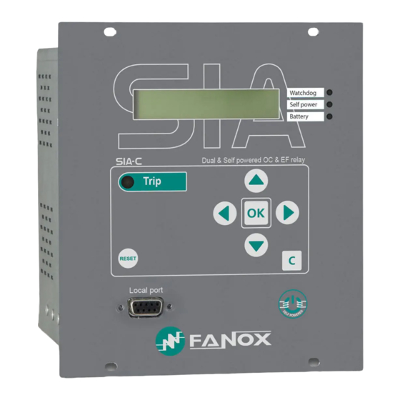
- Page 1 SIA-C Dual & Self powered overcurrent & earth fault relay USER´S MANUAL Sia_Manu_Siac_Ing_R026...
- Page 2 DIMENSIONS AND CONNECTION DIAGRAMS ..........8 2.1. Case Dimensions mm of SIA-C with mechanics type A ............8 2.2. Case Dimensions mm of SIA-C with mechanics type B and C .......... 10 2.3. Case Dimensions mm of SIA-C with mechanics type D ............. 12 2.4.
- Page 3 24 Vdc or 48 Vdc auxiliary power supply ................ 108 5.13. Equipment starting up time. Fault trip time during starting up of the equipment..108 5.13.1. SIA-C for striker ....................... 109 5.13.2. SIA-C withdrawable model ....................111 5.13.3. SIA-C for coil ........................113 5.14.
- Page 4 8.2. Function codes ........................172 8.3. Exemptions an error answers ..................... 173 8.4. Data type..........................173 8.5. Memory map of SIA-C ......................174 8.6. Counters Map ........................178 8.7. Commands Map ........................178 8.8. Examples of ModBus frames ....................179 Writing the access password “5555”...
- Page 5 10.1. Identification ........................182 10.2. Checks ..........................183 10.3. Test menu .......................... 183 10.4. Register of commissioning settings ................183 10.5. Inputs ..........................185 10.6. Outputs ..........................185 10.7. Leds ............................ 185 10.8. Comments ......................... 186 www.fanox.com Rev. 26 5/188...
-
Page 6: Reception, Handling, Installation
It is necessary to inspect the equipment at the time it is delivered to ensure that the relays have not been damaged during transport. If any defect is found, the transport company and FANOX should be informed immediately. If the relays are not for immediate use, they should be returned to their original packaging. -
Page 7: Installation, Commissioning And Service
All electrical power sources should be removed before performing this operation to avoid the risk of electrical discharge. This product must be disposed of in a safe way. It should not be incinerated or brought into contact with water sources like rivers, lakes, etc… www.fanox.com Rev. 26 7/188... -
Page 8: Dimensions And Connection Diagrams
2. DIMENSIONS AND CONNECTION DIAGRAMS Vertical assembly Withdrawable Vertical assembly Horizontal assembly 2.1. Case Dimensions mm of SIA-C with mechanics type A www.fanox.com Rev. 26 8/188... - Page 9 Cut-out pattern www.fanox.com Rev. 26 9/188...
-
Page 10: Case Dimensions Mm Of Sia-C With Mechanics Type B And C
2.2. Case Dimensions mm of SIA-C with mechanics type B and C www.fanox.com Rev. 26 10/188... - Page 11 Cut-out pattern www.fanox.com Rev. 26 11/188...
-
Page 12: Case Dimensions Mm Of Sia-C With Mechanics Type D
2.3. Case Dimensions mm of SIA-C with mechanics type D Cut-out pattern www.fanox.com Rev. 26 12/188... -
Page 13: Case Dimensions Mm Of Sia-C With Mechanics Type E And G
2.4. Case Dimensions mm of SIA-C with mechanics type E and G Cut-out pattern www.fanox.com Rev. 26 13/188... -
Page 14: Case Dimensions Mm Of Sia-C With Mechanics Type F (Withdrawable)
2.5. Case Dimensions mm of SIA-C with mechanics type F (withdrawable) Cut-out pattern www.fanox.com Rev. 26 14/188... -
Page 15: Kitcom Dimensions
2.6. KITCOM Dimensions www.fanox.com Rev. 26 15/188... -
Page 16: Striker Dimensions (In Mm)
2.7. Striker Dimensions (in mm) 44,5 49,5 56,5 64,5 42,5 www.fanox.com Rev. 26 16/188... -
Page 17: Tcm Dimensions
2.8. TCM Dimensions www.fanox.com Rev. 26 17/188... -
Page 18: Connection Diagrams
Connection diagrams 2.9.1. Separated terminals connectors for measurement and power supply Connection diagram. 3 phase transformers: Power Supply and Measurement – Sensitive Neutral – Trip: Striker Neutral Sensitive Neutral Trip Striker Supply 230Vac (depending on model) www.fanox.com Rev. 26 18/188... - Page 19 Connection diagram. 3 phase transformers: Power Supply and Measurement – Sensitive Neutral – Trip: Coil + TCM Neutral Sensitive Neutral Trip Striker + TCM Supply 230Vac (depending on model) www.fanox.com Rev. 26 19/188...
- Page 20 Connection diagram. 3 phase transformers: Power Supply and Measurement – Sensitive Neutral – Trip: ATC (free potential trip) Neutral Sensitive Neutral Trip Supply 230Vac (depending on model) www.fanox.com Rev. 26 20/188...
- Page 21 Connection diagram. 3 phase transformers: Power Supply and Measurement – Solid Neutral – Trip: Striker Neutral Solid neutral Trip Striker Supply 230Vac (depending on model) www.fanox.com Rev. 26 21/188...
- Page 22 Connection diagram. 3 phase transformers: Power Supply and Measurement – Solid Neutral – Trip: Coil + TCM Neutral Solid neutral Trip Supply 230Vac (depending on model) www.fanox.com Rev. 26 22/188...
- Page 23 Connection diagram. 3 phase transformers: Power Supply and Measurement – Solid Neutral – Trip: ATC (free potential trip) Neutral Solid neutral Trip Supply 230Vac (depending on model) www.fanox.com Rev. 26 23/188...
- Page 24 Connection diagram. 3 phase transformers: Power Supply – 3 phase transformers: Measurement – Solid Neutral – Trip: Striker Neutral Solid neutral Trip Striker Supply 230Vac (depending on model) www.fanox.com Rev. 26 24/188...
- Page 25 Connection diagram. 3 phase transformers: Power Supply – 3 phase transformers: Measurement – Solid Neutral – Trip: Coil + TCM Neutral Solid neutral Trip Supply 230Vac (depending on model) www.fanox.com Rev. 26 25/188...
- Page 26 Connection diagram. 3 phase transformers: Power Supply – 3 phase transformers: Measurement – Solid Neutral – Trip: ATC (Potential Free Trip) Neutral Solid neutral Trip Supply 230Vac (depending on model) www.fanox.com Rev. 26 26/188...
- Page 27 Connection diagram. 3 phase transformers: Power Supply – 3 phase transformers: Measurement – Sensible Neutral – Trip: Striker Neutral Sensible neutral Trip Striker Supply 230Vac (depending on model) For trip: Trip: Coil + TCM and trip: ATC, the same as in previous examples www.fanox.com Rev. 26 27/188...
- Page 28 In SIACxxxx4xxxxx, external trip is at 230 Vac. Connection diagrams are as follow: 3 phase transformers: Power supply and measurement - sensible neutral: www.fanox.com Rev. 26 28/188...
- Page 29 3 phase transformers: Power supply and measurement - solid neutral www.fanox.com Rev. 26 29/188...
- Page 30 3 phase transformers: Measurement, 3 phase transformer: Power supply - solid neutral www.fanox.com Rev. 26 30/188...
- Page 31 3 phase transformers: Measurement, 3 phase transformer: Power supply - sensible neutral www.fanox.com Rev. 26 31/188...
-
Page 32: Simple Terminals Connector (Measurement And Power Supply)
2.9.2. Simple terminals connector (measurement and power supply) 3 phase transformers: Power supply and measurement - solid neutral www.fanox.com Rev. 26 32/188... - Page 33 Connection diagram. 3 phase transformers: Power Supply and Measurement – Solid Neutral – Trip: Coil + TCM www.fanox.com Rev. 26 33/188...
- Page 34 Connection diagram. 3 phase transformers: Power Supply and Measurement – Solid Neutral – Trip: ATC (free potential trip) www.fanox.com Rev. 26 34/188...
- Page 35 3 phase transformers: Power supply and measurement - solid neutral and external trip at 230 vac www.fanox.com Rev. 26 35/188...
- Page 36 Mechanic G Three phase transformers: Power supply and measurement – Solid neutral www.fanox.com Rev. 26 36/188...
- Page 37 Mechanic F Three phase transformers: Power supply and measurement – Solid neutral Wiring diagram for WITHDRAWABLE version of SIA-C www.fanox.com Rev. 26 37/188...
-
Page 38: Terminals
2.10. Terminals 2.10.1. Physical layout of SIA-C type A and D terminals www.fanox.com Rev. 26 38/188... - Page 39 Phase B current output for power supply Digital output 2 NO Phase C current input for power supply Trip output positive contact Phase C current output for power supply Trip output negative contact RS485 gnd RS485 - RS485 + ╧ Earthing screw www.fanox.com Rev. 26 39/188...
- Page 40 Phase A current input for power supply Phase A current output for power supply Phase B current input for power supply Phase B current output for power supply Phase C current input for power supply Phase C current output for power supply www.fanox.com Rev. 26 40/188...
- Page 41 Phase A current output for power supply Earthing screw Phase B current input for power supply Phase B current output for power supply Phase C current input for power supply Phase C current output for power supply www.fanox.com Rev. 26 41/188...
-
Page 42: Physical Layout Of Sia-C Types B And C Terminals
2.10.2. Physical layout of SIA-C types B and C terminals www.fanox.com Rev. 26 42/188... - Page 43 Digital 1 common output Measurement & power supply Digital output 1 NA Digital output 2 NC Digital 2 common output Digital output 2 NA Trip output positive Trip output gnd RS485 gnd RS485 – RS485 + ╧ Earthing screw www.fanox.com Rev. 26 43/188...
- Page 44 Digital 2 common output Measurement & power supply Digital output 2 NO Neutral current input for Measurement & power supply Neutral current output for Trip output positive Measurement & power supply Trip output negative ╧ Earthing screw www.fanox.com Rev. 26 44/188...
- Page 45 Phase C current input for Trip output negative Measurement & power supply Phase C current output for Earthing screw ╧ Measurement & power supply Neutral current input for Measurement & power supply Neutral current output for Measurement & power supply www.fanox.com Rev. 26 45/188...
-
Page 46: Physical Layout Of Sia-C Type E Terminals
2.10.3. Physical layout of SIA-C type E terminals www.fanox.com Rev. 26 46/188... - Page 47 Digital 1 common output power supply Digital output 1 NO Digital output 2 NC Digital 2 common output Digital output 2 NO Trip output positive contact Trip output negative contact RS485 gnd RS485 - RS485 + ╧ Earthing screw www.fanox.com Rev. 26 47/188...
- Page 48 Phase C current input for Measurement & Trip output negative contact power supply Phase C current output for Measurement & Earthing screw ╧ power supply Neutral current input for Measurement & power supply Neutral current output for Measurement & power supply www.fanox.com Rev. 26 48/188...
- Page 49 Phase C current output for Measurement & Digital 2 common output power supply Neutral current input for Measurement & Digital output 2 NO power supply Neutral current output for Measurement & Trip output positive power supply Trip output negative ╧ Earthing screw www.fanox.com Rev. 26 49/188...
-
Page 50: Physical Layout Of Sia-C Type F Terminals (Withdrawable Model)
2.10.4. Physical layout of SIA-C type F terminals (withdrawable model) Phase A current input for Measurement & power supply Phase A current output for Measurement & power supply Phase B current input for Measurement & power supply Phase B current output for Measurement & power supply Phase C current input for Measurement &... -
Page 51: Physical Layout Of Sia-C Type G Terminals
2.10.5. Physical layout of SIA-C type G terminals Phase A current input for Measurement & power supply Phase A current output for Measurement & power supply Phase B current input for Measurement & power supply Phase B current output for Measurement & power supply Phase C current input for Measurement &... -
Page 52: Description
SIcom program, allowing for precise coordination with other equipment. One of the most significant features of the SIA-C is that it eliminates the need for maintenance, as it uses the operating current to power itself. Additional benefits include that all of the models have been designed to be supplied from an external battery. - Page 53 This serves as a backup to the overcurrent functions. The SIA-C equipment comes in a metal box with galvanic isolation on all of its measurement, trip or power supply inputs and outputs (with the exception of ports for communications and the battery power supply, as these are sporadic connections).
- Page 54 The protection offered by the SIA-C against earth faults is sensitive enough to be used in electric systems where the earth fault current is low. It can be set to 0.1 times the rated neutral current and, depending on the model, the rated neutral current can go as low as 0.1 A.
- Page 55 The main features of the equipment are listed below, and these features will be explained in the rest of the manual: Function Description SIA-C Protection Phase instantaneous overcurrent protection function 1(*) 50N/G Neutral instantaneous overcurrent protection function 1(*) 50/51P Phase inverse time overcurrent protection function...
- Page 56 Function Description SIA-C Control and signalling HMI: LCD, 20x2 and 6 keys + 1 reset button Bistable magnetic indicators Up to 3 LED Indicators Up to 3 Signalling outputs (2 outputs) Optional 2 inputs and 2 outputs Optional Signalling outputs (3outputs)
-
Page 57: Functional Diagram
3.3. Functional Diagram NOTE 1: In SIACXXXXXXXXXXA there are two levels of 50P function (50P_1, 50P_2) and two levels of 50N/G function (50N/G_1, 50N/G_2). NOTE 2: SIACXXXXXXXXXXB model is provided with CLP protection function. www.fanox.com Rev. 26 57/188... -
Page 58: Selection & Ordering Data
Vertical, Compact Size, 3 Flags, Backlight LCD, withdrawable Vertical, Compact Size, 1 Flag, Backlight LCD ADAPTATION 50P + 50/51P + 50N/G + 50/51N/G + 86 + PLC + 50P_2 + 50N/G_2 + 3 Settings group +CLP + 4 Settings groups www.fanox.com Rev. 26 58/188... -
Page 59: Phase Ct And Neutral Ct Selection
0.2-30 A 0.2-30 A SIAC51 CT 5 A CT 1 A 1-150 A 0,2-30 A SIAC1A CT 1 A CT 0.1 A 0.2-30 A 0.02-3 A SIAC1B CT 1 A CT 0.2 A 0.2-30 A 0.04-6 A www.fanox.com Rev. 26 59/188... -
Page 60: Load Curve For Relay Sia-C/1
3.5.1. Load curve for relay SIA-C/1 LOAD CURVE FOR RELAY SIA-C/1 SIAC/1 Circuito de Autoalimentacion y Medida SIAC/1 Circuito de Medida 3.5.2. Load curve for relay SIA-C/5 LOAD CURVE FOR RELAY SIA-C/5 SIAC/5 Circuito de Autoalimentacion y Medida SIAC/5 Circuito de Medida www.fanox.com... -
Page 61: Protection Functions
4. PROTECTION FUNCTIONS 4.1. General settings Aditionally, it is necessary to define some previous parameters that will provide the SIA-C relay information about what and how it is going to protect. Group Description Minimum Maximum Step Unit Default Generales “enter your text”... -
Page 62: P Function. Phase Inverse Time Overcurrent
The function activates at 100% of the preset input, and deactivates at 95%. The reset is instantaneous. The accuracy of the operation time is equal to the preset time ±30ms or ±0.5% (whichever is greater). (*) NOTE: 50N/G_2 available in SIACXXXXXXXXXXA model www.fanox.com Rev. 26 62/188... -
Page 63: N/G Function. Neutral Inverse Time Overcurrent
Pickup function is not in working conditions. Cold Load Time: After the circuit has been closed, during this time the new setting group is applied. After this time, the relay returns to the adjusted setting group. www.fanox.com Rev. 26 63/188... - Page 64 When the setting group changed occurs, not all the protection functions change, only 50P, 50/51P, 50N/G and 50/51N/G functions are modified to new settings. www.fanox.com Rev. 26 64/188...
-
Page 65: External Trip
Input 2: block the trip of functions 50N/G and 50/51N/G It consists on implementing a trip bus using SIA-C relays. As you can see on the picture, there are two relays with feeder functionality and one relay with supply functionality. - Page 66 PULSE operation. The adjusted time must be the time of feeder’s functions (time delay setting), plus the trip holding time (in SIA-C this time is approximately 200 ms), plus the security time (to ensure the signal has dropped off).
- Page 67 Please, take into account that 50 and 51 functions keep the trip output activated during the holding time (200ms), once the trip condition disappears. The inputs of the supply relay should be connected to the blocking signals directly through an www.fanox.com Rev. 26 67/188...
- Page 68 The supply will not trip because the feeder makes the fault disappear before its time of operation is finished. www.fanox.com Rev. 26 68/188...
- Page 69 The feeder will block the supply the adjusted time, but in this case, the time of operation of the supply is larger that this blocking time, so the supply will trip once its time of operation finishes since it can still see the fault. www.fanox.com Rev. 26 69/188...
-
Page 70: Protection Settings
4.9. Protection Settings The SIA-C settings are listed below with their description, maximums, minimums, units and the values for the factory settings. Group Description Minimum Maximum Step Unit Default Phase instantaneous overcurrent 50P_1 (**)50P_2 Permission Yes/No 0,10 30,00 0,01 I nominal... - Page 71 When the frequency is changed it is necessary to reinitialize the relay to ensure that the setting is loaded correctly. Trip level voltage parameter appears in all models, but only has sense in models for striker. Every setting change involves the reset of the functions, activated or not. www.fanox.com Rev. 26 71/188...
-
Page 72: Settings Table
Regarding other options, regardless of that established by the settings, the inputs prevail over the settings. If the use of both inputs is not required, then one can be used, but depending on which is used, operation can be done with table 1 or table 2. www.fanox.com Rev. 26 72/188... -
Page 73: Iec60255-151 Curves
4.11. IEC60255-151 Curves The SIA-C relay complies with the curves shown in standard IEC60255-151: Inverse Curve Very Inverse Curve Extremely Inverse Curve Long time inverse There is a general mathematical equation that defines the time in seconds as a function of the current: ... - Page 74 Rev. 26 74/188...
- Page 75 Rev. 26 75/188...
- Page 76 Rev. 26 76/188...
- Page 77 Rev. 26 77/188...
-
Page 78: Ansi-Ieee Curves
Very Inverse 19,61 0,491 Inverse 0,0515 0,02 0,114 The curve can move from its axis using the TD time selection device, which the user can adjust. is the initial operating current, set by the user. adjusted www.fanox.com Rev. 26 78/188... - Page 79 Rev. 26 79/188...
- Page 80 Rev. 26 80/188...
- Page 81 Rev. 26 81/188...
-
Page 82: Application Examples
=1100 Ap, IEC inverse curve defines a tripping value of 0.1425s (Figure1) for 50/51 function. It is considered that this time is too high, so when current fault reaches 11xI definite time overcurrent function will be work. www.fanox.com Rev.26 82/188... - Page 83 The figure below (Figure 2), shows the tripping curve of the relay: Figure 2. Relay tripping curve www.fanox.com Rev.26 83/188...
- Page 84 , definite time overcurrent function will be work. 50 function tap is adjusted at 14xIn so definite time overcurrent function will trip when current fault is higher than 14xIn (50 function does not wait to reach 24xIn) www.fanox.com Rev.26 84/188...
- Page 85 The figure below (Figure 4), shows the tripping curve of the relay: Figure 4. Relay tripping curve www.fanox.com Rev.26 85/188...
- Page 86 =1500 Ap, Definite time curve defines a tripping value of 5 s (Figure 5) for 50/51 function. It is considered that this time is too high, so when current fault reaches 15xI , definite time overcurrent function will be work function 50). www.fanox.com Rev.26 86/188...
- Page 87 The figure below (Figure 6), shows the tripping curve of the relay: Figure 6. Relay tripping curve www.fanox.com Rev.26 87/188...
-
Page 88: Monitoring And Control
Phase r.m.s. currents (IA, IB, IC) Neutral r.m.s. current (IN) Maximum current (IMax) Below are shown the phase and neutral ranges of the SIA-C models: Model Phase range Neutral range I rated phase I rated neutral SIAC5*... -
Page 89: Status And Events
50P_2 Phase C trip 50P_2 Trip Phase inverse time overcurrent 50/51P Phase A Pickup 50/51P Phase B Pickup 50/51P Phase C Pickup 50/51P 50/51P Pickup 50/51P Phase A trip 50/51P Phase B trip 50/51P Phase C trip www.fanox.com Rev.26 89/188... - Page 90 52 definitive Open Close Cold Load Open Cold Load Cold Load pickup General status General trip External trip Battery supply Trip power error General 50 Hz network frequency Measurement error Ready Protection error Settings changed Time and date synchronisation www.fanox.com Rev.26 90/188...
- Page 91 50N Trip Phase Trip Aux. Power Self-Power Battery Physical inputs Ext Trip (not configurable) Inputs (*) Input 1 (configurable) Input 2 (configurable) Physical Outputs Trip output (not configurable) Outputs Output 2 (*)(configurable) Output 3 (*)(configurable) Output 4 (*)(configurable) www.fanox.com Rev.26 91/188...
- Page 92 Setting change: This activates when the settings are changed. Date-time set: This activates when the date-time are synchronised. Communication in local: this is the sum of the "MMI activity" and "Local communication" bits from the "Local communication" status group www.fanox.com Rev.26 92/188...
- Page 93 "delete events" command. Events have the following structure: Identify Unique event identifier: e.g.: 51_1.4 = 51P START Value ON(Activated) /OFF(Deactivated): an event is generated for activations and deactivations Year Month Time Minutes Seconds Milliseconds www.fanox.com Rev.26 93/188...
- Page 94 50/51N/G Pick-up 50/51N/G Pick-up Activation/Deactivation Neutral current 50/51N/G bit-12 50/51N/G Trip 50/51N/G Trip Activation/Deactivation Neutral current Instantaneous neutral overcurrent bit-04 50N/G Pick-up 50N/G Pick-up Activation/Deactivation Neutral current 50N/G_1 (*)50N/G_2 bit-12 Activation/Deactivation 50N/G Trip 50N/G Trip Neutral current www.fanox.com Rev.26 94/188...
- Page 95 Factory settings bit-11 Activation/Deactivation Eeprom Error Eeprom Error bit-12 Activation/Deactivation Eeprom change Eeprom change bit-13 Activation/Deactivation Events error Events error bit-16 Pickup bit-17 Pickup Phase A bit-18 Pickup Phase B bit-19 Pickup Phase C bit-20 Ground pickup www.fanox.com Rev.26 95/188...
- Page 96 Led 1 bit-01 Led 2 bit-02 Led 3 Outputs bit-03 Trip Output Trip Output Activation/Deactivation bit-04 Output 2 (*) Output 2 Activation/Deactivation bit-05 Output 3 (*) Output 3 Activation/Deactivation bit-06 Activation/Deactivation Output 4 (*) Output 4 www.fanox.com Rev.26 96/188...
-
Page 97: Fault Reports
List of all events occurred in the equipment during the fault. To delete the fault reports buffer, position the cursor over the fault report menu and press and hold the "RESET" key, until there is no fault reports. There will be an event "Fault reports erased". www.fanox.com Rev.26 97/188... -
Page 98: Self-Diagnosis
5.6. Date-time synchronisation All models of relay SIA-C are provided with a real time clock (RTC), which can be synchronized by HMI or by communications. RTC keeps the data updated during at least 72 hours without power supply. Charge time for the capacitor is 10 minutes. -
Page 99: Digital Inputs
5.7. Digital inputs The SIA-C (depending on model) has 2 digital inputs that can be configured by the user. The inputs can be configured from the HMI or through the SICom program. Physical inputs are the equipment’s real inputs. The SIA-C has two physical inputs: Input 1 and Input 2. -
Page 100: Programmable Logic Control & Digital Outputs
Firstly, it is defined the concept of physical input, physical output and logical signal. Physical inputs are the real inputs of the device. SIA-C device has, depending on model, up to two physical inputs (Input 1 and Input 2). These inputs are translated to two internal binary states which later, can be assigned to logical signal to get a specific operation. - Page 101 In V3 of the PLC the LOGICAL GATES that are supported by SIA-C are: LOGICAL GATE HMI SYMBOL NOR4 Ю OR4_LACTH Φ NOR4_LACTH ⌠ OR4_PULSES AND4 & NAND4 § AND4_PULSES OR_TIMER_UP NOR_TIMER_UP AND_TIMER_UP NAND_TIMER_UP OR_PULSE NOR_PULSE AND_PULSE NAND_PULSE By default, outputs configuration is:...
- Page 102 Output 4 NOR4 Ready GENERAL TRIP OR4_PULSES General Trip (NOT CONFIGURABLE) Block 50P Not configured ------ Block 50N Not configured ------ LOGICAL SIGNALS Active settings group 1 Not configured ------ Active settings group 2 Not configured ------ www.fanox.com Rev.26 102/188...
-
Page 103: Function. Trip Output Lockout
OR4_LACTH is chosen the block of this output is being permited. 5.11. Test program The SIA-C equipment has a test menu that can be used to check the operation of the signalling components (LEDs and magnetic indicators), along with the trip output and the signalling outputs. - Page 104 OK; if the item is activated, it is deactivated by pressing “OK”). Press the “C” key to exit the test menu. In order to obtain more detailed information, the method for navigating the menus is explained graphically in the keypad and display section. www.fanox.com Rev.26 104/188...
-
Page 105: Power Supply
SIA-C equipment rated at 5 A current powers itself with 1 A of single phase current and with 500 mA of three phase current, and the SIA-C rated at 1 A of current powers itself with 200 mA of single phase current and with 100 mA of three phase current. It is... - Page 106 How to switch the KITCOM on: To switch the KITCOM on it is necessary to move the switch situated on a side of the device. Once the switch has been moved, a green led will inform the device is switched on: www.fanox.com Rev.26 106/188...
-
Page 107: Vac Or 110 Vac, 50/60 Hz Auxiliary Power
The continuous operation of SIA-C is guaranteed with the levels of self-power (0,2 x Inominal single phase and 0,1 x Inominal three phase) and the auxiliary power supply 230Vac/110Vac. -
Page 108: Vdc Or 48 Vdc Auxiliary Power Supply
The most critical case is produced when there is self-power (without auxiliary voltage nor battery) and low current faults. In order to reduce to the maximum the SIA-C tripping time when there is a fault during the energization of the equipment, the model SIACXXXXXXX2XX has developed (with non-volatile RAM memory and fast startup). -
Page 109: Sia-C For Striker
5.13.1. SIA-C for striker SIA-C1 1200 1000 Time (ms) FAST & 3 PHASE Time (ms) FAST & 1 PHASE 1200 Time (ms) NORMAL & 3 PHASE Time (ms) NORMAL & 1 PHASE 1460 x In Without auxiliary voltage nor battery www.fanox.com... - Page 110 SIA-C5 1200 1000 Time (ms) FAST & 3 PHASE Time (ms) FAST & 1 PHASE Time (ms) NORMAL & 3 PHASE Time (ms) NORMAL & 1 PHASE 1060 x In Without auxiliary voltage nor battery www.fanox.com Rev.26 110/188...
-
Page 111: Sia-C Withdrawable Model
5.13.2. SIA-C withdrawable model In this item it is developed the situation of trip onto fault of SIAC11500032AFA (withdrawable model) This relay is operative with 0.2 times the secondary rated single-phase current and with 0.1 times the secondary rated three-phase current; in other words, the equipment powers itself with 200 mA of single-phase current and with 100 mA of three-phase current. - Page 112 970 ms. This time decreases with the current and it stabilizes at 5 amperes with a tripping time equal to 60 miliseconds. From this value onwards the tripping time will maintain equal to 60 miliseconds, www.fanox.com Rev.26 112/188...
-
Page 113: Sia-C For Coil
5.13.3. SIA-C for coil Without auxiliary voltage nor battery SIA-C1 Time (ms) FAST & 3 PHASE 96,1 75,8 64,2 61,6 60,8 60,5 Time (ms) FAST & 1 PHASE 316,3 182,1 110,7 84,7 65,7 64,3 63,8 Time (ms) NORMAL & 3 PHASE Time (ms) NORMAL &... - Page 114 63,5 62,9 Time (ms) FAST & 1 PHASE 221,9 124,2 71,9 65,2 65,2 Time(ms) NORMAL & 3 PHASE 215,3 174,2 156,4 152,8 151,7 150,8 Time (ms) NORMAL & 1 PHASE 345,4 181,9 162,3 156,9 152,8 x In www.fanox.com Rev.26 114/188...
-
Page 115: Opening Mechanism
The opening mechanism is activated by means of a striker or a coil. The activation of the trip generates a pulse train. The equipment SIA-C solves the next situations during the activation of the opening mechanism: ... -
Page 116: Striker Activation
It requires the use of SIA-C models with trip output for striker (SIACXXXX0XXXXX, SIACXXXX1XXXXX and SIACXXXX4XXXXXX). The activation of the SIA-C trip output means that a capacitor has discharged on the output terminals. This discharge of energy is sufficient to activate a striker that mechanically acts on a mechanism to open the current circuit. -
Page 117: Coil Activation By Means Of A Free Potential Contact
5.14.3. Coil activation by means of TCM adapter This equipment is connected to the relay trip output and supplies the energy (30 J) that is necessary to energise coil-activated opening mechanisms. TCM adapter is combined with SIA-C models that are provided with free potential contact. (Models SIACXXXX2XXXXX SIACXXXX3XXXXX). -
Page 118: Technical Specifications And Standards
Defined time : 0.02 to 300 s (step 0.01 s) Dial: 0.02 to 1.25 (step 0.01) Curve, activation level 110% Curve, deactivation level 100% Defined time, activation level 100% Defined time, deactivation level 95% Instantaneous deactivation Timing accuracy:± 5% or ±30 ms (whichever is greater) www.fanox.com Rev.26 118/188... - Page 119 Function Settings tables (*) Adaptation A: 3 settings tables Activated by inputs or by general settings. Adaptation B: 4 settings tables Activated by inputs or by general settings Fault reports 20 fault reports, 16 events in each www.fanox.com Rev.26 119/188...
- Page 120 230 Vac, ±20 % 110 Vac, ±20 % 24 Vdc ±10 % 48 Vdc ±10 % 85-265 Vdc/Vac ±20 % Battery supply With adapter (Kitcom) port DB9 Self-power from current Three phase self-power level: I > 0,1 x In www.fanox.com Rev.26 120/188...
-
Page 121: Thermal Resistance
3s. IEC 61000-4-18 Common mode for all terminals ±2.5kV. Differential mode for all terminals excepts Communication port ±1kV 1.4. Electrostatic discharge IEC 60255-26 Level 4, Contact discharge ±8kV. Air discharge ±15kV IEC 61000-4-2 www.fanox.com Rev.26 121/188... - Page 122 500V applied between each group to earth and with rest of the groups in short-circuit IEC 60255-5 2.4. Protective bonding resistance IEC 60255-27 Test current 2xIn, Test voltage 12Vac during 60s. Resistance shall be less than 0.1 ohm www.fanox.com Rev.26 122/188...
- Page 123 IEC 60068-21-2 7.4. Seismic IEC 60255-21-3 Single Axis Sine Sweep, Class 1, X Axis: 1 to 9Hz, 3.5mm and 9 to 35Hz, 1g ; Y Axis: 1 to IEC 60068-21-3 9Hz, 1.5mm and 9 to 35Hz, 0.5g www.fanox.com Rev.26 123/188...
- Page 124 Declared on manual, without damage for continuous operation 8.4. VT Input short time overload IEC 60255-27 Declared on manual, without damage for 10s short time overloading 9. Enclosure protection IEC 60255-27 IP-54 IEC 60529 Quality Management System ISO 9001:2008 www.fanox.com Rev.26 124/188...
-
Page 125: Communication And Hmi
7.3. Rear communication. RS485 An option exists to fit the SIA-C with a rear communications port RS485, which must be specified when the model is selected. The RS485 port output has three terminals (+,- and GND), located on the rear of the equipment. - Page 126 Connection diagram for a RS485 bus: www.fanox.com Rev.26 126/188...
-
Page 127: Bistable Magnetic Indicators
Model 1 bistable There is a general trip wothout indicating the reason. Apart from this signaling, the LCD will show the text <<PICK-UP>> when any protection function is activated. 3 Bistable magnetic indicators Withdrawable model 1 Bistable magnetic indicator www.fanox.com Rev.26 127/188... -
Page 128: Led Indicators
7.5. LED Indicators The SIA-C front panel has up to three configurable LED pilot lights. By default, they show the type of power being used: self-power, battery or auxiliary power (in model with mechanic G Led 1 shows, by default, if the relay is not Ready (watchdog )). The LEDs are switched off when the power type that they represent is not active, and they blink when the power type that they represent is active. - Page 129 Healthy: Activated (LED blinking) if it detects the relay is ready LED 2 Self power: Activated (LED blinking) if it detects the self-power current LED 3 Battery: Activated (LED blinking) if it detects voltage from an external battery www.fanox.com Rev.26 129/188...
- Page 130 To get the leds to be operative it is required the following current: Single phase0.35xIn Three phase0.17xIn Once the relay detects these levels of current and the situation that generates the activation of the leds, they are instantaneously activated. www.fanox.com Rev.26 130/188...
-
Page 131: Lcd And Keypad
7.6. LCD and keypad The front of the SIA-C relay is fitted with an alphanumeric LCD screen, measuring 20x2. This screen provides the user with access to read information about the settings parameters, measurements, status and events. All of this information is arranged in a system of menus. In some models this LCD is fitted with backlight. -
Page 132: How To Install Sicom Software
How to install SICOM Software To install the SICom it is necessary the following link: http://fanox.blob.core.windows.net/sicom/publish.htm The link will open the next screen, where key “install” must be pressed: The necessary drivers depending on the operative system can be downloaded from this page. -
Page 133: Setting-Up The Session: Password And Access Levels
(passwords with more or less characters will not be accepted). By default, the equipment is programmed with the following passwords and their associated levels: PASSWORD ACCESS LEVEL 2222 3333 4444 5555 The SIA-C does not have a command feature. The SIA-C does not have a protected settings feature. www.fanox.com Rev.26 133/188... -
Page 134: Menus
▲ and ▼ are used to increase or decrease the value. If an invalid value is entered during the process, the “C” key can be used to delete it. The navigation through the menus is described as graphically as possible below. www.fanox.com Rev.26 134/188... -
Page 135: Date-Time Menu
Sep 9 2014/08:48:44 hold 7.9.5. Communication parameters The communications parameters can be viewed by pressing and maintaining pressed the “▼” key from the standby mode screen. ▼ LOCAL setting SIAC11531112AA 19200-8-N-1 0.00 0.00 0.00 0.00 hold REMOTE setting 19200-8-N-1 www.fanox.com Rev.26 135/188... -
Page 136: Contrast
The contrast menu can be accessed from the standby mode screen by pressing the “◄” key. Contrast level can be changed using the “▲” and “▼” keys. Press the “C” key to return to the standby mode screen. ◄ CONTRAST SIAC11531112AA 0.00 0.00 0.00 0.00 hold www.fanox.com Rev.26 136/188... -
Page 137: Test Menu
“C” key or automatically by waiting 5 minutes without no activity with the keys. WITHDRAWABLE MODEL ◄ ▼ ► TEST MENU y/n? without protection! OK hold Set Password -> 0 Set Password ◄▼▲► -> 5555 TEST MENU Led 1: not activated Led 1: <<ACTIVATED>> Led 2: ▲▼ not activated www.fanox.com Rev.26 137/188... - Page 138 Led 2: <<ACTIVATED>> Led 3: ▲▼ not activated Led 3: <<ACTIVATED>> Trip Output: ▲▼ not activated Trip Output: <<ACTIVATED>> Output 2: ▲▼ not activated Output 2:: <<ACTIVATED>> Output 3: ▲▼ not activated Output 3: <<ACTIVATED>> www.fanox.com Rev.26 138/188...
- Page 139 Output 4: ▲▼ not activated Output 4: <<ACTIVATED>> O/C bistable: ▲▼ not activated O/C bistable: <<ACTIVATED>> HS-OC bistable: ▲▼ not activated HS-OC bistable: <<ACTIVATED>> E/F&HS-O/C bistable: ▲▼ not activated E/F&HS-O/C bistable: <<ACTIVATED>> www.fanox.com Rev.26 139/188...
- Page 140 Rest of the models ◄ ▼ ► TEST MENU y/n? without protection! OK hold Set Password -> 0 Set Password ◄▼▲► -> 5555 TEST MENU Led 1: not activated Led 1: <<ACTIVATED>> Led 2: ▲▼ not activated Led 2: <<ACTIVATED>> www.fanox.com Rev.26 140/188...
- Page 141 Led 3: ▲▼ not activated Led 3: <<ACTIVATED>> 50P/51P bistable: ▲▼ not activated 50P/51P bistable: <<ACTIVATED>> 50N/51N bistable: ▲▼ not activated 50N/51N bistable: <<ACTIVATED>> Ext trip bistable: ▲▼ not activated www.fanox.com Rev.26 141/188...
- Page 142 Ext trip bistable: <<ACTIVATED>> Trip bistable: not activated Trip bistable: <<ACTIVATED>> Trip Output: ▲▼ not activated Trip Output: <<ACTIVATED>> Output 2: ▲▼ not activated Output 2: <<ACTIVATED>> Output 3: ▲▼ not activated Output 3: <<ACTIVATED>> www.fanox.com Rev.26 142/188...
-
Page 143: Functions Menu
NOTE: Be careful when activating the Trip Output. When the equipment is installed, this opens the circuit as if it were a trip. 7.9.8. Functions menu The SIA-C relay menu is split up into 4 main parts: Measurements. - Page 144 Press the “OK” key to access the second level from the main screen. Use the ▲ and ▼ keys to move from one menu section to another in the second level. Use the “C” key to return to a higher level. www.fanox.com Rev.26...
-
Page 145: Measurements Menu
“OK”. Use the “▲” and “▼” keys to position the cursor over the measurement and to see its value. SIAC11531112AA ↑ MEASUREMENTS 0.00 0.00 0.00 0.00 ↓ 0.00 A ▲▼ 0.00 A ▲▼ 0.00 A ▲▼ 0.00 A ▲▼ IMAX 0.00 A By default primary measurements are displayed. Press “OK”· to view secondary measurements. www.fanox.com Rev.26 145/188... -
Page 146: Status Menu
0.00 ↓ ↑ Sta. 50P STATES ↓ Sta. 50P Phase A Pickup not activated Phase B Pickup: ▲▼ not activated Phase C Pickup: ▲▼ not activated Phase Pickup: ▲▼ not activated Phase A Trip: ▲▼ not activated www.fanox.com Rev.26 146/188... - Page 147 ↑ Sta. 51P STATES ▲▼ ↓ Phase A Pickup: Sta. 51P not activated Phase B Pickup: ▲▼ not activated Phase C Pickup: ▲▼ not activated Phase Pickup: ▲▼ not activated Phase A Trip: ▲▼ not activated www.fanox.com Rev.26 147/188...
- Page 148 ▲▼ not activated ↑ Sta. 50N STATES ▲▼ ↓ Ground Pickup: Sta. 50N not activated Ground Trip: ▲▼ not activated ↑ STATES Sta. 51N ▲▼ ↓ Ground Pickup: Sta. 51N not activated Ground Trip: ▲▼ not activated www.fanox.com Rev.26 148/188...
- Page 149 ↑ Sta. CLP STATES >CLP Disable ↓ CLP Disable Sta. CLP >CLP Disable <<ACTIVATED>> 52 Close ▲▼ not activated 52 Open ▲▼ not activated 52 Definitive open ▲▼ not activated Close Cold Load ▲▼ not activated www.fanox.com Rev.26 149/188...
- Page 150 Cold Load pickup ▲▼ not activated Sta. GENERAL ↑ STATES ▲▼ >ACTIVATED ↓ Trip: Sta. GENERAL not activated >ACTIVATED External trip: ▲▼ not activated Error TripPower: ▲▼ not activated 50Hz: ▲▼ <<ACTIVATED>> TripBlck Enab: ▲▼ not activated www.fanox.com Rev.26 150/188...
- Page 151 Error Measure: ▲▼ not activated Ready: ▲▼ <<ACTIVATED>> Setting change: ▲▼ not activated Set Date/Time: ▲▼ not activated Local Act.:: ▲▼ <<ACTIVATED>> FactorySetting: ▲▼ not activated Error Eeprom: ▲▼ not activated Eeprom changed: ▲▼ not activated www.fanox.com Rev.26 151/188...
- Page 152 Phase B Pickup: ▲▼ not activated Phase C Pickup: ▲▼ not activated Ground Pickup: ▲▼ not activated Phase A Trip: ▲▼ not activated Phase B Trip: ▲▼ not activated Phase C Trip: ▲▼ not activated www.fanox.com Rev.26 152/188...
- Page 153 Ground Trip: ▲▼ not activated 50P Trip: ▲▼ not activated 50N Trip: ▲▼ not activated Phase Trip: ▲▼ not activated Aux. Power: ▲▼ not activated Self-Power. Power: ▲▼ not activated Battery: ▲▼ <<ACTIVATED>> www.fanox.com Rev.26 153/188...
- Page 154 Ext. Trip Sta. INPUTS not activated Input 1: ▲▼ not activated Input 2: ▲▼ not activated ↑ STATES Sta. OUTPUTS ▲▼ ↓ Sta. OUTPUTS TripOutput: ▲▼ not activated Output 2: ▲▼ not activated Output 3: ▲▼ not activated www.fanox.com Rev.26 154/188...
- Page 155 Sta. LEDS ↑ STATES ▲▼ ↓ >Activated Led 1 Sta. LEDS not activated Led 2: ▲▼ not activated Led 3: ▲▼ <<ACTIVATED>> Sta. LOGIC ↑ STATES ↓ 50P Block ▲▼ not activated 50N Block ▲▼ not activated www.fanox.com Rev.26 155/188...
- Page 156 ↓ Local COM.: Sta. LOCAL not activated >Activated MMI Activity: ▲▼ <<ACTIVATED>> ↑ Sta. REMOTE STATES ↓ Sta. REMOTE Remote COM. SIACxxxxxxxxxxA will show two 50P functions (50P1 and 50P2) and two 50N/G functions (50N/G_1 and 50N/G_2) www.fanox.com Rev.26 156/188...
-
Page 157: Settings Menu
The keys ▲, ▼, ◄ and ► are used to enter the password. ▲ and ▼ are used to introduce a value or a character, and the ◄ and ► keys are used to move from one character to another. If it is necessary to change one of the password characters or numbers due to an error, press "C" to delete it. Press "OK” to validate the password. www.fanox.com Rev.26 157/188... - Page 158 -> 5555 Time Delay Function Enable ▲▼ 0.2 s NO -> NO Sett(1) 51P ▲▼ Function Enable ▲▼ NO -> YES Function Enable Function Enable NO > YES y/n Curve type SETTING CHANGED ▲▼ E.I. Function Enable www.fanox.com Rev.26 158/188...
- Page 159 Time Dial Function Enable ▲▼ 1.25 Current Tap ▲▼ 1.00 xIn(1.00) Time Delay ▲▼ 0.2 s Sett(1) 50N1 ▲▼ Function Enable ▲▼ Current Tap 1.00 xIn(1.00) ▲▼ Time Delay 0.2 s Sett(1) 51N ▲▼ Function Enable www.fanox.com Rev.26 159/188...
- Page 160 Set Password ◄▼▲► 0.50 xIn(1.00) -> 5555 ▲▼ Time Delay Time Dial 0.2 s 1.25 -> 0 Time Dial ◄▼▲► 1.25 -> 0.5 Time Dial 1.25 > 0.5 y/n SETTING CHANGED Time Dial Time Dial 0.50 Sett(1) CLP www.fanox.com Rev.26 160/188...
- Page 161 Function Enable Active Settings G. ▲▼ No Load Time ▲▼ 15.00 s Cold Load time ▲▼ 15.00 s Identification ◄ Free text Frequency ▲▼ 50 Hz Serial Number ▲▼ www.fanox.com Rev.26 161/188...
- Page 162 Local COM Address ▲▼ Remote Address ▲▼ Remote Baudrate ▲▼ 19200 SIACxxxxxxxxxxA will show two 50P functions (50P1 and 50P2) and two 50N/G functions (50N/G_1 and 50N/G_2). “Active settings G.” is only available in SIACxxxxxxxxxxA and SIACxxxxxxxxxxB models. www.fanox.com Rev.26 162/188...
-
Page 163: Events Menu
To delete the events buffer, position the cursor over the events menu and press and hold the "RESET" key, until password is requested. Introduce the password and prees OK until there is only one event shown. This one event is "Deleted events". www.fanox.com Rev.26... - Page 164 Position of the event within the list of events Events generated by a status activation or reset Associated measurement (if it has one) Time event/total events Associated measurement Date 01/01/00 00:54:18600 1/1023 measurement Events erased Events erased Activated or Not activated Event description www.fanox.com Rev.26 164/188...
-
Page 165: Demand Menu
From the standby mode screen, press the “OK” key to access the first line of menus. Use the “▲” and “▼” keys to position the cursor over the “DEMAND” screen.. SIAC11531112AA 0.00 0.00 0.00 0.00 12/04/12 01:57:03260 MAX: 60.65 A Each Demand register contains the following information: Date-time Maximun Current Time Date 12/04/12 00:54:18600 Max: 60.65A Maximum Current www.fanox.com Rev.26 165/188... -
Page 166: Fault Reports
To delete the fault reports, position the cursor over the fault report menu and press and hold the "RESET" key, until password is requested. Introduce the password and prees OK until there is a massage informing “fault reports erased”." www.fanox.com Rev.26... -
Page 167: Plc And Output Configuration Menu
Phase B Pickup: ▲▼ not activated Phase B Pickup: Sta. 50P ► > Led1 y/n? Phase B Pickup: Phase B Pickup: Sta. 50P ▲▼ ◄ > Led2 y/n? > Led2 y/n? Configuration Processing... Con 1/4 Led2 Phase B Pickup www.fanox.com Rev.26 167/188... - Page 168 Phase B Pickup: & > Led2 y/n? ◄ Phase B Pickup: > Led2 y/n? ◄ Phase B Pickup: § > Led2 y/n? ◄ Phase B Pickup: ◄ > Led2 y/n? Phase B Pickup: ◄ > Led2 y/n? www.fanox.com Rev.26 168/188...
- Page 169 ◄ Phase B Pickup: > Led2 y/n? ◄ Phase B Pickup: ◄ > Led2 y/n? Phase B Pickup: ▲▼ > Led3 y/n? Phase B Pickup: > Trip Output y/n? Phase B Pickup ▲▼ > Output 2 y/n? www.fanox.com Rev.26 169/188...
- Page 170 1 to 4. The “▲” and “▼” keys can be used in this menu to browse all of the states (up to 4) that are associated with a physical output. Press and hold the “RESET” key while viewing any of the instantaneous states associated with the output and its index number from 1 to 4 to remove the association with the physical output www.fanox.com Rev.26 170/188...
-
Page 171: Modbus Rtu Protocol
8. MODBUS RTU PROTOCOL This document describes the steps to follow to read and write data on the SIA-C relay, as per the ModBUS/RTU protocol. This memory map is only valid for one piece of equipment and one version of the memory. -
Page 172: Modbus Package Format
The registers are values of 2 bytes of length, transmitted with the most important byte at first. The maximum number of register to be written in a package is 60. www.fanox.com Rev.26 172/188... -
Page 173: Exemptions An Error Answers
UINT Integer without sign of 2 bytes Integer with sign of 2 bytes LONG Integer without sign of 4 bytes DWORD Integer with sign of 4 bytes Number in floating decimal point “Float” of 4 bytes FLOAT www.fanox.com Rev.26 173/188... -
Page 174: Memory Map Of Sia-C
VOLT When the data format takes up more than one BYTE, the most important BYTE is sent through the communications first, and the least important BYTE is sent last. 8.5. Memory map of SIA-C Number of Function Description Start address... - Page 175 BIT32 events section State reading 50/51N/G in status and BIT32 events section State reading Inputs in status and BIT32 events section State reading Outputs in status and BIT32 events sectionº State reading Remote communication BIT32 states map www.fanox.com Rev.26 175/188...
- Page 176 03 y 16 Setting FLOAT F50/51P Definite time 03 y 16 Setting DENUM NOSI F50N/G_1 Permission 03 y 16 Setting FLOAT F50N/G_1 Tap 03 y 16 Setting FLOAT F50N/G_1 Operating time 03 y 16 Setting DENUM NOSI F50/51N/G Permission www.fanox.com Rev.26 176/188...
- Page 177 Confirm setting LONG Remote address Confirm setting DENUMBAUD Remote Baudrate Confirm setting DENUM NOSI F50P_1 Permission Confirm setting FLOAT F50P_1 Tap Confirm setting FLOAT F50P_1 Operating time Confirm setting DENUM NOSI F50/51P Permission Confirm setting DENUMCURVA F50/51P Curve www.fanox.com Rev.26 177/188...
-
Page 178: Counters Map
FCLP Settings group Confirm setting FLOAT FCLP No Load Time Confirm setting FLOAT FCLP Cold Load Time 8.6. Counters Map The SIA-C does not dispose of Counters. 8.7. Commands Map The SIA-C does not dispose of Commands. www.fanox.com Rev.26 178/188... -
Page 179: Examples Of Modbus Frames
Number of Bytes Password 35,35,35,35 checksum H checksum L And the SIA will reply OK: address function H start address L start address Number of H registers Number of L registers Number of Bytes checksum H checksum L www.fanox.com Rev.26 179/188... -
Page 180: Commissioning
Therefore, the secondary circuits of current transformers should never be opened. 9.7. Auxiliary power If an SIA-C relay with auxiliary power is required, this must be specified on the order reference. The amount of auxiliary power required for the SIA-C relay should be checked. www.fanox.com Rev.26... -
Page 181: Rs232 Front Communications Port
9.8. RS232 Front communications port To perform this test, connect a PC with the SICom software program to the SIA-C relay, and check that there are no communication errors. If a laptop computer is used, the connector will probably be a USB. It is important to check the assigned communications port. -
Page 182: Appendix
10. APPENDIX 10.1. Identification Date:………….....……………………………………………………………………………… Manager: …….....…………………………………………………………………………………… Substation:..………………………………………………………………………………………… Circuit:..……………………………………………………………………………………....Model:..………………………………………………………………………………………....Serial no.: ....……………………………………………………………………………………… Software Versions:.....……………………………………………………………………………… www.fanox.com Rev.26 182/188... -
Page 183: Checks
(Some of the LEDS, outputs and bistables depend on model) 10.4. Register of commissioning settings Password:……………….......………………………………………………………………… Identification:. ………………………………………………………………………………… CT Ratio: Phase CT Ratio: ………………………………………………………………………………… Neutral CT Ratio: ………………………………………………………………………………… 50P_1 Enabled Disabled Permission …………..… xIn Defined Time…………..s www.fanox.com Rev.26 183/188... - Page 184 Extrm. Inverse LT Inverse IEC curve type ANSI curve type Inverse Very Inverse Extrm. Inverse Def. Time Dial………………....Defined Time………………s Enabled Disabled Permission Settings group....……………… No Load Time……………… Cold Load Time……………… www.fanox.com Rev.26 184/188...
-
Page 185: Inputs
10.5. Inputs External trip: Input 1: Input 2: 10.6. Outputs Trip Output Output 2: Output 3: Output 4: 10.7. Leds Led 1 Led 2: Led 3: www.fanox.com Rev.26 185/188... -
Page 186: Comments
10.8. Comments ……………………………………………………………………………………………………..…… ……………………………………………………………………………………………………..…… ……………………………………………………………………………………………………..…… ……………………………………………………………………………………………………..…… ……………………………………………………………………………………………………..…… ……………………………………………………………………………………………………..…… ……………………………………………………………………………………………………..…… ……………………………………………………………………………………………………..…… ……………………………………………………………………………………………………..…… ……………………………………………………………………………………………………..…… ……………………………………………………………………………………………………..…… ……………………………………………………………………………………………………..…… ……………………………………………………………………………………………………..…… ……………………………………………………………………………………………………..…… ……………………………………………………………………………………………………..…… ……………………………………………………………………………………………………..…… ……………………………………………………………………………………………………..…… ……………………………………………………………………………………………………..…… ……………………………………………………………………………………………………..…… ……………………………………………………………………………………………………..…… ……………………………………………………………………………………………………..…… ……………………………………………………………………………………………………..…… ……………………………………………………………………………………………………..…… ……………………………………………………………………………………………………..…… Person in charge of commissioning…………………………….. Date…………..............… Maintenance performed on the………………….. by …………………………………………….. www.fanox.com Rev.26 186/188... - Page 187 NOTES ……………………………………………………………………………………………………..…… ……………………………………………………………………………………………………..…… ……………………………………………………………………………………………………..…… ……………………………………………………………………………………………………..…… ……………………………………………………………………………………………………..…… ……………………………………………………………………………………………………..…… ……………………………………………………………………………………………………..…… ……………………………………………………………………………………………………..…… ……………………………………………………………………………………………………..…… ……………………………………………………………………………………………………..…… ……………………………………………………………………………………………………..…… ……………………………………………………………………………………………………..…… ……………………………………………………………………………………………………..…… ……………………………………………………………………………………………………..…… ……………………………………………………………………………………………………..…… ……………………………………………………………………………………………………..…… ……………………………………………………………………………………………………..…… ……………………………………………………………………………………………………..…… ……………………………………………………………………………………………………..…… ……………………………………………………………………………………………………..…… ……………………………………………………………………………………………………..…… ……………………………………………………………………………………………………..…… ……………………………………………………………………………………………………..…… ……………………………………………………………………………………………………..…… ……………………………………………………………………………………………………..…… ……………………………………………………………………………………………………..…… ……………………………………………………………………………………………………..…… ……………………………………………………………………………………………………..…… ……………………………………………………………………………………………………..…… ……………………………………………………………………………………………………..…… ……………………………………………………………………………………………………..…… ……………………………………………………………………………………………………..…… ……………………………………………………………………………………………………..…… ……………………………………………………………………………………………………..…… ……………………………………………………………………………………………………..…… ……………………………………………………………………………………………………..…… www.fanox.com Rev.26 187/188...
- Page 188 Rev.26 188/188...
Need help?
Do you have a question about the SIA-C and is the answer not in the manual?
Questions and answers