
Related Manuals for FANOX SIL-D00


Summary of Contents for FANOX SIL-D00
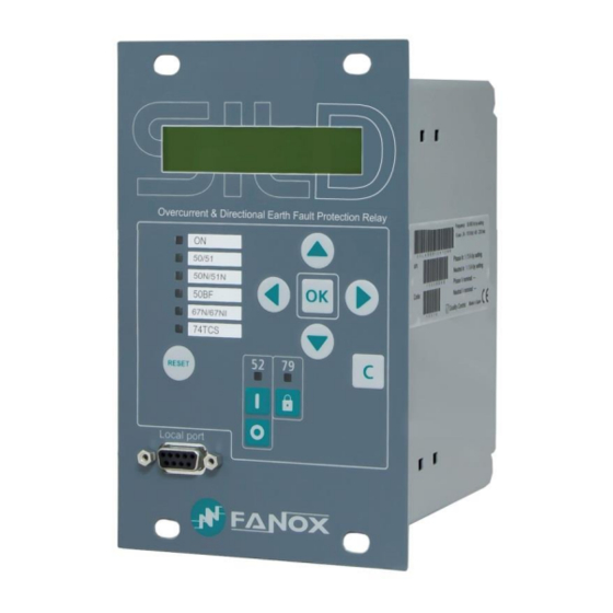
- Page 1 SIL D Overcurrent and Directional Earth-Fault Relay USER´S MANUAL SER´S MANUAL EN_SIL_MANU_SILD_R006.Docx...
-
Page 2: Table Of Contents
Function 74TCS. Trip circuit supervision ............... 39 4.10. Function 79. Autorecloser ....................40 4.10.1. Counter to record the number of reclosings ................. 43 4.11. Function CLP. Cold Load Pickup ..................44 4.12. Trip block for switch disconnector .................. 45 www.fanox.com Rev.06 2/226... - Page 3 Setting up the session: Password and access levels ..........100 7.6. Menus ..........................101 7.6.1. Standby mode screen ....................101 7.6.2. Last Trip screen ......................101 7.6.3. Accessing the menus ....................102 7.6.4. Date-Time Menu ......................102 7.6.5. Fault report ........................103 www.fanox.com Rev.06 3/226...
- Page 4 Point list ........................... 202 11.4. DNP3 protocol settings ....................205 MODBUS TCP PROTOCOL ..............206 12.1. ModBus package format ....................206 12.2. Function codes ........................ 207 12.3. Exemptions and error answers ..................207 12.4. Data type .......................... 207 www.fanox.com Rev.06 4/226...
- Page 5 Test menu: ........................217 14.4. Register of commissioning settings: ................217 14.5. Inputs: ..........................222 14.6. Logical signals ......................... 222 14.7. Outputs configuration ..................... 223 14.8. Leds configuration ......................223 14.8.1 Leds configuration Template: ..................223 14.9. Comments ........................224 www.fanox.com Rev.06 5/226...
-
Page 6: Reception, Handling, Installation
It is necessary to inspect the equipment at the time it is delivered to ensure that the relays have not been damaged during transport. If any defect is found, the transport company and FANOX should be informed immediately. If the relays are not for immediate use, they should be returned to their original packaging. -
Page 7: Installation, Commissioning And Service
All electrical power sources should be removed before performing this operation to avoid the risk of electrical discharge. This product must be disposed of in a safe way. It should not be incinerated or brought into contact with water sources like rivers, lakes, etc… www.fanox.com Rev.06 7/226... -
Page 8: Dimensions And Connection Diagrams
2. DIMENSIONS AND CONNECTION DIAGRAMS 2.1. Equipment front view www.fanox.com Rev.06 8/226... -
Page 9: Equipment Dimensions
2.2. Equipment dimensions www.fanox.com Rev.06 9/226... -
Page 10: Cut-Out Pattern
2.3. Cut-out pattern www.fanox.com Rev.06 10/226... -
Page 11: Connection Diagrams
3 phase CTs or 2 phase CTs and 1 neutral CT. It is important to perform the correct connection between relay and CTs to avoid erroneous measurement and thus avoid a wrong protection. www.fanox.com Rev.06 11/226... - Page 12 Digital connections (Only as an example) www.fanox.com Rev.06 12/226...
-
Page 13: Terminals
2.5. Terminals www.fanox.com Rev.06 13/226... - Page 14 (*) When the model is chosen it is very important to choose the communications protocols correctly. If “RS485” port is chosen then “E” communications module is not available. If “E” communications module is chosen then “RS485” port is not available. www.fanox.com Rev.06 14/226...
-
Page 15: Description
Worldwide, the energy sector is currently undergoing a profound change as a result of high levels of energy demand; more distribution lines and advanced supervision systems are required. Given the need for creating intelligent infrastructure, FANOX has developed the SIL family of products to carry out this function. - Page 16 PC to be connected and the equipment to be monitored using the SICom program in WINDOWS 7, WINDOWS 8, WINDOWS 8.1 or WINDOWS 10 (supplied by FANOX). The rear communication ports are designed for different functions. While one is used for control,...
- Page 17 Phase and neutral rms currents with a precision of 2% in a band of ✓ ±20% when compared to the rated current, and 4% in the rest of the range (IA, IB, IC, IN) ✓ Neutral voltage (VR) ✓ Angle between neutral voltage and neutral current ✓ Maximum current www.fanox.com Rev.06 17/226...
- Page 18 Events saved in the non-volatile FRAM* memory 200 events 5 Records (100 cycles per record) Oscillography records in the non-volatile FRAM* memory 20 fault reports (24 events each one) ✓ Real-Time Clock (RTC 1 millisecond) ✓ Test menu ✓ Self-diagnosis www.fanox.com Rev.06 18/226...
-
Page 19: Functional Diagram
Adjustments Table By general settings 4 setting tables By Inputs Mechanical 4U x 1 4 ⁄ rack Dimensions 3.3. Functional Diagram www.fanox.com Rev.06 19/226... -
Page 20: Selection & Ordering Codes
RS232 (Modbus RTU) + RJ45 (DNP3.0 TCP/IP) RS232 (Modbus RTU) + RJ45 (IEC 60870-5-104) Inputs and Outputs 6 Inputs + 4 Outputs. Mechanics Vertical Assembly Languages English, Spanish and German English, Spanish and Turkish English, Spanish and French English, Turkish and Russian Adaptation www.fanox.com Rev.06 20/226... -
Page 21: Phase Ct And Neutral Ct Selection
Neutral nominal current Model nominal Phase range Neutral range current Residual phase connection, SIL-D00 1 A or 5 A 0.1 -30 A or 0.5-150 A 0.2-30A or 1-150A 1A or 5A 0.1-30 A or 0.5-150 A Residual phase connection, SIL-D0S 1 A or 5 A 0.1-30 A or 0.5-150 A... -
Page 22: Sil-D/1 Charge Curve
3.5.1. SIL-D/1 charge curve 0,04 0,03 0,02 0,01 SILA/1 Circuito de Medida SILD/1 measurement circuit 3.5.2. SIL-D/5 charge curve 0,05 SILA/5 Circuito de Medida SILD/5 measurement circuit www.fanox.com Rev.06 22/226... -
Page 23: Protection Functions
0.02 2.20 0.01 1,25 0.10 7.00 0.01 1,00 nominal Time delay 0.02 300.0 0.01 0,02 (1*) IEC Inverse, IEC Very Inverse , IEC Extremely Inverse , IEC long time inverse, IEEEInverse, IEEEvery inverse, IEEEextremely inverse, Defined time www.fanox.com Rev.06 23/226... -
Page 24: Function 50N/G. Instantaneous Neutral Overcurrent
The function activates at 100% of the preset input, and deactivates at 95%. The reset is instantaneous. The accuracy of the Time delay is equal to the preset time ±30 ms or ±0.5% www.fanox.com Rev.06 24/226... -
Page 25: Function 67N. Inverse Time Directional Neutral Overcurrent
If the unit operates with definite-time, the function starts up at 100% of the adjusted pickup and resets at 95%. If the unit operates with a curve, the function starts up at 110% of the adjusted pickup and resets at 100%. Resets are instantaneous in both cases. www.fanox.com Rev.06 25/226... - Page 26 The curves that are used are IEC 60255-151 and IEEE, which are described in the corresponding section. The following figures show a graphic representation of the directional actuation zone, adjusted with an operating angle of 90° and a half-cone angle of 60°: Forward www.fanox.com Rev.06 26/226...
- Page 27 Besides the Directionality parameter, the ‘Reverse Directionality’ signal permits being configured to a digital input to change the function to reverse directionality when the DI is active despite the function was adjusted as direct directionality. www.fanox.com Rev.06 27/226...
- Page 28 With these settings, when a residual current is higher than 1A, delayed more than 15º and less than 165º on the residual voltge, if the residual voltage is higher than 40V, the function 67N will act in a time of 0.1 sec. www.fanox.com Rev.06 28/226...
-
Page 29: Function 67Ni. Directional Neutral Isolated Overcurrent
To perform the module evaluation , it is used the residual voltage and the residual current measurements, defining a working area according the settings of low and high currents and the low and high voltages. Working area characteristic of I0 and V0 www.fanox.com Rev.06 29/226... - Page 30 Besides the Directionality parameter, the ‘Reverse Directionality’ signal permits being configured to a digital input to change the function to reverse directionality when the DI is active despite the function was adjusted as direct directionality. www.fanox.com Rev.06 30/226...
- Page 31 Low current: 0.5 (In=1) • High current: 2 (In=1) • Low voltage: 9V • High voltage: 40V • Operating time: 0.1s • Operating angle: 90º • Halfcone angle: 90º The directional operation area will be defined according the following characteristic: www.fanox.com Rev.06 31/226...
- Page 32 With these parameters, when a residual voltage and current are inside the working area (I.e. 2A and 40V), if the residual current is delayed more than 15º and less than 165º on the residual voltage, the function 67NI will act in a time of 0.1 sec. www.fanox.com Rev.06 32/226...
-
Page 33: Function 59N. Definite-Time Neutral Overvoltage
The function pick up occurs at 100% of the adjusted input and the dropout at 95%. The reset type is temporized and reset time is adjusted with reset time parameter. The accuracy of the Time delay is equal to the preset time ±30 ms or ±0.5% www.fanox.com Rev.06 33/226... -
Page 34: Function 52. Circuit Breaker Monitoring
Activated if the accumulated amps counter exceeds "Maximum accumulated accumulated (l2t) amps amps" setting exceeded Activated the number of openings exceeds the setting in "Maximum Repeated Trips repeated openings" for the time set in "Time of maximum repeated openings" www.fanox.com Rev.06 34/226... - Page 35 This physical input is then assigned to the "52b Input” logical input. The 52a logical input is calculated internally as the negative of 52b. The circuit breaker performance is shown in the following finite state machine: www.fanox.com Rev.06 35/226...
-
Page 36: Circuit Breaker Opening And Closing Commands
"Maximum number of openings" status is activated and its corresponding event is generated. This counter reading can be set to any value from within its range from the HMI or by communications. www.fanox.com Rev.06 36/226... -
Page 37: Accumulated Amps Counter: I T
Both parameters can be adjusted. When this number is exceeded, the "Repeated Trips" status is activated and its corresponding event is generated. This alarm resets itself, when the corresponding time is exceeded with less trips than those indicated. www.fanox.com Rev.06 37/226... -
Page 38: Function 50Bf. Circuit Breaker Opening Failure
When the current via the three phases is less than 8% of the rated current, the circuit breaker is considered to be open. There is a signal “50BF init” to start the open fault from an external protection. The “50BF init” is configurable by user. The default configuration is shown below: • General trip www.fanox.com Rev.06 38/226... -
Page 39: Function 74Tcs. Trip Circuit Supervision
This functionality is achived through configurable digital inputs. In this case, it is verified the continuity of the coils. This function settings are as follows: Group Description Minimum Maximum Step Unit Default Trip circuit supervision 74TCS Permission Yes/No Time delay 0.02 300.00 0.01 2.00 www.fanox.com Rev.06 39/226... -
Page 40: Function 79. Autorecloser
0.02 300.00 0.01 180.00 Reclose 4 time 0.02 300.00 0.01 180.00 Reclose 5 time 0.02 300.00 0.01 180.00 Hold time 0.02 300.00 0.01 10.00 Replacement time 0.02 300.00 0.01 10.00 Final Opening Time 0.02 300.00 0.01 10.00 www.fanox.com Rev.06 40/226... - Page 41 In the first four cases, the equipment stores the lock situation in the non-volatile memory, as the last control must be know for a possible re-start. The auto-recloser´s start up is shown in the following figure: There are two stable conditions here, Standby and Lockout, the other conditions are transient. www.fanox.com Rev.06 41/226...
- Page 42 Wait Reclose Condition No Hold Time Hold TimeOut Time Reclose Condition Input Close TimeOut Time 52 Close Reset TimeOut Time 52 Close & 79 Unblock Command Safety TimeOut Time LOCKOUT 52 Open 79 Block Input + 79 Block Command www.fanox.com Rev.06 42/226...
-
Page 43: Counter To Record The Number Of Reclosings
79 closing time bit. The “79 init” status is an adjustable logical signal. 4.10.1. Counter to record the number of reclosings The SIL-D equipment is fitted with a counter that records the number of reclosings. www.fanox.com Rev.06 43/226... -
Page 44: Function Clp. Cold Load Pickup
When the new setting group is applied, not every protection functions change, only functions 50, 50/51, 50N/G and 67N/67NI are modified according this new setting group. www.fanox.com Rev.06 44/226... -
Page 45: Trip Block For Switch Disconnector
In order to deal with these situations, tripping is blocked when the phase current exceeds a pre-set value. Group Description Minimum Maximum Step Unit Default Trip block protection for switchdisconnector Blocking Yes/No Blocking limit 1.50 20.00 0.01 I nominal 7.00 www.fanox.com Rev.06 45/226... -
Page 46: General Settings
English in all cases. Consult the list of models to find out which are available 5. Active table: see Settings Table. 6. Nominal phase current: it is possible to select the secondary phase nominal current. Depending on model the options are: 5 A, 1A, 0.5 A or 2.5 A www.fanox.com Rev.06 46/226... -
Page 47: Settings Table
Regarding other options, regardless of that established by the settings, the inputs prevail over the settings. If the use of both inputs is not required, then one can be used, but depending on which is used, operation can be done with table 1 or table 2. www.fanox.com Rev.06 47/226... -
Page 48: Iec 60255-151 Curves
Long Time Inverse Ext. Inverse Very Inverse 13,5 Inverse 0,14 0,02 The curve can mode from its axis using the D time selection device, which the user can adjust. is the initial operating current, set by the user. adjusted www.fanox.com Rev.06 48/226... - Page 49 Rev.06 49/226...
- Page 50 Rev.06 50/226...
- Page 51 Rev.06 51/226...
- Page 52 Rev.06 52/226...
-
Page 53: Ieee Curves
0,1217 Very Inverse 19,61 0,491 Inverse 0,0515 0,02 0,114 The curve can move from its axis using the TD time selection device, which the user can adjust. is the initial operating current, set by the user. adjusted www.fanox.com Rev.06 53/226... - Page 54 IEEE Inverse 1000,000 100,000 Dial 10,000 0,05 Dial 0,1 Dial 0,2 Dial 0,5 Dial 0,8 Dial 1 Dial 1,2 1,000 0,100 0,010 10,0 100,0 I/It www.fanox.com Rev.06 54/226...
- Page 55 IEEE Very Inverse 1000,000 100,000 Dial 10,000 0,05 Dial 0,1 Dial 0,2 Dial 0,5 Dial 0,8 Dial 1 Dial 1,2 Dial 1,5 1,000 Dial 2 0,100 0,010 10,0 100,0 I/It www.fanox.com Rev.06 55/226...
- Page 56 IEEE Extremely Inverse 1000,000 100,000 Dial 0,05 10,000 Dial 0,1 Dial 0,2 Dial 0,5 Dial 0,8 Dial 1 Dial 1,2 Dial 1,5 Dial 2 1,000 Dial 2,2 0,100 0,010 10,0 100,0 I/It www.fanox.com Rev.06 56/226...
-
Page 57: Application Examples
Primary current: I =100 A 50/51 function settings • Curve type: IEC Inverse • Dial: 0.05 • Tap: 1xI 50 function settings • Tap: 11xI • Time delay: 0.05 s Figure 1. 50 y 50/51 IEC Inverse www.fanox.com Rev.06 57/226... - Page 58 Transformation ratio of CT =500/1 • Primary current: I =500 A 50/51 function settings • Curve type: IEEE Extremely Inverse • Dial: 2.20 • Tap: 1xI 50 function settings • Tap: 14xI • Time delay: 0.1 s www.fanox.com Rev.06 58/226...
- Page 59 14xIn so definite time overcurrent function will trip when current fault is higher than 14xIn (50 function does not wait to reach 24xIn) The figure below (Figure 4), shows the tripping curve of the relay: Figure 4. Relay tripping curve www.fanox.com Rev.06 59/226...
- Page 60 Primary current: Ip=100 A 50/51 function settings • Curve type: Definite time • Tap 1xIn • Time delay: 5 s 50 function settings • Tap: 15xIn • Time delay: 1 s Figure 5. Function 50/51 (as 50) and function 50. www.fanox.com Rev.06 60/226...
- Page 61 5) for 50/51 function. It is considered that this time is too high, so when current fault reaches 15xI , definite time overcurrent function will be work function 50). The figure below (Figure 6), shows the tripping curve of the relay: Figure 6. Relay tripping curve www.fanox.com Rev.06 61/226...
-
Page 62: Monitoring And Control
0.5 A or 0.1 A A transformer with a suitable current must be used to ensure correct operation. . Frequency Rated 50 Hz or 60 Hz. ± 3 Hz Thermal resistance Four times the continuous rated current www.fanox.com Rev.06 62/226... -
Page 63: Current Demand
Sampling rate (interval): configurable through communications: 1 – 60 min • Record format: Date/Time IMAX (in interval) IMAX (actual) 5.3. Counters The following counters are provided: Number of openings of the circuit breaker Amperes accumulated (l2t) during the openings of the circuit breaker Number of shots www.fanox.com Rev.06 63/226... -
Page 64: States And Events
"Events deleted". To delete the events using communications, use the corresponding "delete events" command. Events have the following structure: Identifier Unique event identifier: e.g.: 51_1.4 = 51P PICKUP ON(Activated) /OFF(Deactivated): Value an event is generated for Activation and deActivation Year Month Time Minutes Seconds Milliseconds www.fanox.com Rev.06 64/226... - Page 65 Active group by Activation Setting group NO. input Activation Corriente de fase Activation Corriente de fase Activation Corriente de fase Oscilography Activation Corriente de neutro Neutral Tap Activation Function tap Phase Tap Activation Function tap Reports erased Activation www.fanox.com Rev.06 65/226...
- Page 66 50N/G_2 Trip 50N/G_2 Trip Activation/Deactivation Neutral current Bit-00 CLP Disable Bit-01 52 Close Bit-02 52 Open Bit-03 52 definitive Open Bit-04 Close Cold Load Bit-05 Open Cold Load Bit-12 Cold Load pickup Cold load Pickup Activation/Deactivation Phase current www.fanox.com Rev.06 66/226...
- Page 67 Bit-00 Input 1 Input 1 Activation/Deactivation Bit-01 Input 2 Input 2 Activation/Deactivation Bit-02 Input 3 Input 3 Activation/Deactivation Entradas Bit-03 Input 4 Input 4 Activation/Deactivation Bit-04 Input 5 Input 5 Activation/Deactivation Bit-05 Input 6 Input 6 Activation/Deactivation www.fanox.com Rev.06 67/226...
- Page 68 Neutral current Bit-12 67N_2 Trip 67N_2 Trip Activation/Deactivation Neutral current 67NA_2 67N_2 Polarization 67N_2 Polarization Bit-15 Activation/Deactivation Neutral angle Angle Angle Bit-04 59N pickup 59N pickup Activation/Deactivation Neutral voltage Bit-12 59N Trip 59N Trip Activation/Deactivation Neutral voltage www.fanox.com Rev.06 68/226...
- Page 69 Pulse Lock 79 Activation Modbus identifier Remoto Command Bit-20 Pulse Unlock 79 Pulse Unlock 79 Activation identifier Command Bit-21 Local control Local control Activation identifier Command Bit-22 Telecontrol Telecontrol Activation identifier Command Bit-23 Reset Reset Activation identifier www.fanox.com Rev.06 69/226...
- Page 70 The Ready bit agglutinates correct relay operation and has the following logic: Operation Ready Mesaurement error Protection error Default settings This bit is normally assigned to a contact with an NC contact. Measurement error: The self-diagnosis algorithms have detected a problem in the measurement block. www.fanox.com Rev.06 70/226...
- Page 71 HMI Activity: this condition is active if any key has been pressed in the last 15 minutes. Pressing a key implies that the relay is in local. Local control / Telecontrol: It is enabled or there is no telecontrol. www.fanox.com Rev.06 71/226...
-
Page 72: Fault Reports
Local protocol. The performance is identical to the HMI, the relay synchronises the date and time and executes a new synchronisation event. Remote protocols. These protocols can include continuous synchronisation sections. For this reason, the execution of synchronisation events is inappropriate. www.fanox.com Rev.06 72/226... -
Page 73: Oscillography
79 Standby 67N_2 Pickup Phase Block 79 Lockout 67NI_1 Pickup 79 Reclosing time 50_1 Phase A Pickup 67NI_2 Pickup Input 1 50_1 Phase B Pickup Input 2 50_1 Phase C Pickup Input 3 50_2 Phase A Pickup www.fanox.com Rev.06 73/226... - Page 74 Analog channels = 4 Digital channels = 48 Oscillo = 1 Date/Time = 12/5/2014 - 09:52:18.570 **************************************************************** An oscillography is started when the "fault init" state is activated; this is a configurable logical signal. The default configuration is as follows: www.fanox.com Rev.06 74/226...
- Page 75 It is possible to visualize the oscillography using SICom software Using SICom software, it is possible to save the oscillo as a COMTRADE file www.fanox.com Rev.06 75/226...
- Page 76 External trip 50P block Reverse directionality Fault init 79 Pickup 79 Permission Level 79 Lock Pulse 79 Lock Pulse 79 unlock 50BF Pickup Table 1 Table 2 Reset Continuity A Continuity B Logical signal 1 Logical signal 2 www.fanox.com Rev.06 76/226...
-
Page 77: Configurable Outputs
LED 1 LED 2 LED 3 LED 4 LEDs LED 5 LED 6 LED 52 LED 79 Output 1 Output 2 PHYSICAL OUTPUTS Output 3 Output 4 External Trip LOGICAL SIGNALS 50BF start Fault start 50P block www.fanox.com Rev.06 77/226... - Page 78 In V3 of the PLC the LOGICAL GATES that are supported by SIL-D are: LOGICAL GATE HMI SYMBOL NOR4 OR4_LACTH Φ NOR4_LACTH OR4_PULSES AND4 & NAND4 § AND4_PULSES OR_TIMER_UP NOR_TIMER_UP AND_TIMER_UP NAND_TIMER_UP OR_PULSE NOR_PULSE AND_PULSE NAND_PULSE www.fanox.com Rev.06 78/226...
- Page 79 Input Output The configured signal waits the adjusted milliseconds to activate itself. Input Output The configured signal will be activated till it is externally reset (command, reset key, communications…), though the input signal drops off. Input Output www.fanox.com Rev.06 79/226...
- Page 80 67NI-1 Trip • 67NI-2 Trip • LED 6 OR4_LACTH 74TCS Alarm • LED 52 52 Closed • LED 79 79 Standby • Output 1 Ready PHYSICAL • 79 Close time OUTPUTS Output 2 • Local close breaker www.fanox.com Rev.06 80/226...
- Page 81 General trip 79 Init 79 Enable Not configured 79 Block Not configured Lock 79 Not configured Unlock 79 Not configured Continuity A Not configured Continuity B Not configured Logical signal 1 Not configured Logical signal 2 Not configured www.fanox.com Rev.06 81/226...
- Page 82 • General trip detection of breaker failure by 50BF function. When general trip is activated, fault start logical • Fault Init OR4_LACTH output will be activated and it will generate a new General trip fault register. www.fanox.com Rev.06 82/226...
-
Page 83: Function. Trip Output Lockout
Problem in the events recording On the other hand, a default settings error indicates that the relay is operating with default settings, whereby it will not trip (check that the relay alarm is activated with default settings). www.fanox.com Rev.06 83/226... -
Page 84: Commands
If telecontrol is used, it is recommended to configure a led to display when telecontrol is permitted and when it is not. 5.15. Date-time synchronisation The equipment can be synchronised from the HMI or by using communications. www.fanox.com Rev.06 84/226... -
Page 85: Test Program
Led-52 deactivated led-52 Activated Led-52 activated Deactivated Output deactivated Output 1 Activated Output activated Deactivated Output deactivated Output 2 Activated Output activated Deactivated Output deactivated Output 3 Activated Output activated Deactivated Output deactivated Output 4 Activated Output activated www.fanox.com Rev.06 85/226... -
Page 86: Power Supply
150Vac, the equipment could operate bit this is not guaranteed. Supply from the front is designed for fine tuning, or situations where the auxiliary voltage is not guaranteed. In these cases, complete relay operation is not guaranteed, particularly regarding outputs. www.fanox.com Rev.06 86/226... -
Page 87: Technical Specifications And Standards
Defined time : 0.02 to 300 s (step 0.01 s) Dial: 0.02 to 2.20 (step 0.01) 50/51 Curve, activation level 110% Curve, deactivation level 100% Defined time, activation level 100% Defined time, deactivation level 95% Instantaneous deactivation Timer accuracy: ±5% or ±30 ms (whichever is greater) www.fanox.com Rev.06 87/226... - Page 88 Directionality: No/ Forward/ Reverse 67NI(2) Operation angle: 0 to 359º (step 1º) Halfcone angle: 1 to 170º (step 1º) Defined time, activation level 100% Defined time, deactivation level 95% Timer accuracy: ±5% or ±30 ms (whichever is greater) www.fanox.com Rev.06 88/226...
- Page 89 Replacement time: 0.02 to 300 s (step 0.01 s) Definitive opening time: 0.02 to 300 s (step 0.01 s) Function permission: Yes/No Time delay: 0.02 to 300 s (step 0.01 s) 74TCS Trip continuity, in circuits A and B Configurable inputs www.fanox.com Rev.06 89/226...
- Page 90 Demand of current with the following characteristics: • Number of records: 168 • Recording mode circular • Sampling rate (interval): configurable through communications: 1 – 60 min • Record format: Demand of current Date/Time IMAX (in interval) IMAX (actual) www.fanox.com Rev.06 90/226...
- Page 91 1 Remote port RJ45: IEC 61850, DNP3.0 TCP/IP or IEC 60870-104 Auxiliary power 24-220 Vdc /48-230 Vac ±20% Operating temperature : -10 to 70ºC Environmental Storage temperature: -20 to 80ºC conditions Relative humidity: 95% Transformers Measurement 3 or 4 CT /5 or /1 www.fanox.com Rev.06 91/226...
-
Page 92: Thermal Resistence
Height x Width: 177 x 107 (mm) Characteristics Depth: 122.1 mm IP-54 on pannel (*) Optional depending on model 6.2. Thermal resistence • 4 times rated current continously. • 20 times rated current for 10 s. • 80 times rated current for 1s. www.fanox.com Rev.06 92/226... -
Page 93: Standards
Short field strenght for a duration of 3s. 1000 IEC 61000-4-8 A/m. Frequency 50Hz. 1.12. 100KHz damped oscillatory IEC 61000-4-18 Class 3, Repetition frequency 40Hz, Duration waves of each application 3s. Common mode: ±2.5kV. Differential mode: ±1kV www.fanox.com Rev.06 93/226... - Page 94 IEC 60255-27 5. Communication requirements ModBus RTU IEC 61850 IEC 60870-5-103 IEC 60870-5-104 DNP 3.0 6. Climatic environmental IEC 60255-27 requirements 6.1. Cold IEC 60068-2-1 Cold Operation Ab, -25ºC, 72h Cold transport & Storage Ad, -40ºC, 72h www.fanox.com Rev.06 94/226...
- Page 95 Declared on manual, without damage for overload continuous operation 8.4. VT Input short time IEC 60255-27 Declared on manual, without damage for 10s overload short time overloading 9. Enclosure protection IEC 60255-27 IP-54 IEC 60529 Quality Management System ISO 9001:2008 www.fanox.com Rev.06 95/226...
-
Page 96: Communication And Hmi
The RS485 communications are fitted with auxiliary voltage insulation, but no insulation between the various RS485 communication connectors. Fiber optics can be used in very aggressive environments, and they are connected by using the corresponding converters. www.fanox.com Rev.06 96/226... - Page 97 SIL-D with one RJ45 port for IEC61850, DNP3.0, IEC60870-5-104 or Modbus TCP In this case there is one RJ45 port for IEC 61850 protocol, for DNP 3.0 protocol, for IEC 60870-5-104 protocol or Modbus TCP depending on model. www.fanox.com Rev.06 97/226...
-
Page 98: Lcd And Keypad
Reading and deleting events • Changing the user passwords • Loading settings files • Loading configuration files • Date-time synchronisation • Checking the versions of the equipment • Configuring the Modbus address • Configuring and checking the demand www.fanox.com Rev.06 98/226... -
Page 99: How To Install Sicom Software
7.4.1. How to install SICOM Software To install the SICom it is necessary the following link: http://fanox.blob.core.windows.net/sicom/publish.htm The link will open the next screen, where key “install” must be pressed: The necessary drivers depending on the operative system can be downloaded from this page. -
Page 100: Setting Up The Session: Password And Access Levels
SIcom program. It is possible to change the passwords The password must have 4 characters. By default, the equipment is programmed with the following passwords and their associated levels: PASSWORD ACCESS LEVEL 2222 3333 4444 5555 www.fanox.com Rev.06 100/226... -
Page 101: Menus
07/01/15 13:51:44825 Even is auxiliary power is lost, when the SIL-B regains power, it will retain information on the last trip. The last trip screen will only disappear when the “RESET” button is pressed and held down. www.fanox.com Rev.06 101/226... -
Page 102: Accessing The Menus
“OK” to change the equipment date. Press the “C” key to return to the standby mode screen. The date-time information can be viewed by pressing the “►” key from the main screen. DATE AND TIME SIL-D000C1A12AA 01/01/2000 01:43:25 0.00 0.00 0.00 0.00 ↓ 01/01/2000 01:43 www.fanox.com Rev.06 102/226... -
Page 103: Fault Report
07/01/15 12:08:58828 ┐ 51N Pickup Trip 51P ▲▼ 07/01/15 10:01:11661 7.6.6. Versions From the default screen, pressing the “▲” provides access to the equipment versions: Version: 1.00 1.00 SILD000C1A12AA ▲ 0.00 0.00 0.00 0.00 Sep 27 2016/17:14:01 www.fanox.com Rev.06 103/226... -
Page 104: Communication Parameters
From the default screen, press and hold “◄” key to access to contrast menu. Pressing “▲” and “▼” keys we can change the contrast level. Pressing “C” key we will return to default screen CONTRAST SILD000C1A12AA ◄ 0.00 0.00 0.00 0.00 www.fanox.com Rev.06 104/226... -
Page 105: Test Menu
0.00 0.00 ◄ ▼ ► OK HOLD Set Password SIL-D000C1A12AA -> 0 0.00 0.00 0.00 0.00 Set Password ◄▼▲► -> 5555 SIL-D000C1A12AA TEST MENU 0.00 0.00 0.00 0.00 Led-1: not activated Led-1: <<ACTIVATED>> Led-2: ▲▼ not activated www.fanox.com Rev.06 105/226... - Page 106 Led-2: <<ACTIVATED>> Led-3: ▲▼ not activated Led-3: <<ACTIVATED>> Led-4: ▲▼ not activated Led-4: <<ACTIVATED>> Led-5: ▲▼ not activated Led-5: <<ACTIVATED>> Led-6: not activated Led-6: <<ACTIVATED>> www.fanox.com Rev.06 106/226...
- Page 107 Led-79: ▲▼ not activated Led-79: <<ACTIVATED>> Led-52: ▲▼ not activated Led-52: <<ACTIVATED>> Output 1: ▲▼ not activated Output 1: <<ACTIVATED>> Output 2: ▲▼ not activated Output 2: <<ACTIVATED>> www.fanox.com Rev.06 107/226...
- Page 108 Output 4: ▲▼ not activated Output 4: <<ACTIVATED>> NOTE : Be careful when activating the output which is set to trip. When the equipment is installed it will open the circuit as if it were a trip. www.fanox.com Rev.06 108/226...
-
Page 109: Functional Menu
• Events. • Counters. • Commands. • Demand • Fault report SIL-D000C1A12AA MEASUREMENTS SIL-D000C1A12AA 0.00 0.00 0.00 0.00 0.00 0.00 0.00 0.00 STATES ▲▼ GEN SETTINGS ▲▼ T.A=1 COM EVENTS ▲▼ There are 5 COUNTERS ▲▼ COMMANDS ▲▼ www.fanox.com Rev.06 109/226... -
Page 110: Measurements Menu
“MEASUREMENTS” screen and press “OK”. Use the “▲” and “▼” keys to position the cursor over the measurement and to see its value. ↑ MEASUREMENTS SIL-D000C1A12AA 0.00 0.00 0.00 0.00 ↓ ↑ MEASUREMENTS 0.00 A ↓ 0.00 *A ▲▼ 0.00 A www.fanox.com Rev.06 110/226... - Page 111 ▲▼ 0.00 A ▲▼ 0.00 A 0.00 V D.Ang ▲▼ 0.00 deg IMax 0.00 A www.fanox.com Rev.06 111/226...
-
Page 112: Status Menu
The method for navigating through the status menu is shown graphically below. ↑ STATES SIL-D000C1A12AA 0.00 0.00 0.00 0.00 ↓ ↑ Sta. GENERAL STATES ▲▼ ↓ Trip: Sta. GENERAL not activated 50 Hz: ▲▼ <<ACTIVATED>> TripBlck Enab.: ▲▼ Not activated Error Measure: ▲▼ not activated www.fanox.com Rev.06 112/226... - Page 113 Ready: not activated Setting changed: ▲▼ not activated Set Date/Time: ▲▼ not activated Local Ctrl.: ▲▼ not activated FactorySetting: ▲▼ not activated Error Eeprom: ▲▼ not activated Eeprom changed: ▲▼ not activated Error Event: ▲▼ not activated www.fanox.com Rev.06 113/226...
- Page 114 Phase B pickup: ▲▼ not activated Phase C pickup: ▲▼ not activated Ground pickup: ▲▼ not activated Phase A Trip: ▲▼ not activated Phase B Trip: ▲▼ not activated Phase C Trip: ▲▼ not activated www.fanox.com Rev.06 114/226...
- Page 115 ▲▼ not activated 50N Trip: ▲▼ not activated Phase Trip: ▲▼ not activated ↑ Sta. 50-1 STATES ↓ Phase A Pickup Sta. 50-1 not activated Phase B Pickup: ▲▼ not activated Phase C Pickup: ▲▼ not activated www.fanox.com Rev.06 115/226...
- Page 116 Phase C Trip: ▲▼ not activated Phase Trip: ▲▼ not activated ↑ Sta. 50-2 STATES ▲▼ ↓ Phase A Pickup: Sta. 50-2 not activated Phase B Pickup: ▲▼ not activated Phase C Pickup: ▲▼ not activated www.fanox.com Rev.06 116/226...
- Page 117 ▲▼ not activated Phase B Trip: ▲▼ not activated Phase C Trip: ▲▼ not activated Phase Trip: ▲▼ not activated Sta. 50N-1 ↑ STATES ▲▼ ↓ Ground Pickup: Sta. 50N-1 not activated Ground Trip: ▲▼ not activated www.fanox.com Rev.06 117/226...
- Page 118 ↑ Sta. 51 STATES ▲▼ ↓ Phase A Pickup: Sta. 51 not activated Phase B Pickup: ▲▼ not activated Phase C Pickup: ▲▼ not activated Phase Pickup: ▲▼ not activated Phase A Trip: ▲▼ not activated www.fanox.com Rev.06 118/226...
- Page 119 Phase C Trip: ▲▼ not activated Phase Trip: ▲▼ not activated Sta. 67N-1 ↑ STATES ▲▼ ↓ Pickup: Sta. 67N-1 not activated V0 Activated: ▲▼ not activated Trip: ▲▼ not activated Directionality: ▲▼ not activated www.fanox.com Rev.06 119/226...
- Page 120 Pickup: Sta. 67N-2 not activated V0 Activated: ▲▼ not activated Trip: ▲▼ not activated Directionality: ▲▼ not activated ↑ Sta. 67NI-1 STATES ▲▼ ↓ Pickup: Sta. 67N-1 not activated Trip: ▲▼ not activated Directionality: ▲▼ not activated www.fanox.com Rev.06 120/226...
- Page 121 STATES ▲▼ ↓ Pickup: Sta. 67N-2 not activated Trip: ▲▼ not activated Directionality: ▲▼ not activated Sta. 59N-1 ↑ STATES ▲▼ ↓ Pickup: Sta. 59N-1 not activated Trip: ▲▼ not activated Sta. CLP ↑ STATES ▲▼ ↓ www.fanox.com Rev.06 121/226...
- Page 122 52 Open: ▲▼ not activated 52 Def. open: ▲▼ not activated Close CLP: ▲▼ not activated Open CLP: ▲▼ not activated CLP: ▲▼ not activated ↑ Sta. 79 STATES ▲▼ >Lockout ↓ Standby: Sta. 79 not activated >Lockout www.fanox.com Rev.06 122/226...
- Page 123 79 Hold Time: ▲▼ not activated 79 Close Time: ▲▼ not activated 79 Reset Time: ▲▼ not activated 79 Lockout: ▲▼ not activated 79 Security T.: ▲▼ not activated 79 Manual Open: ▲▼ not activated www.fanox.com Rev.06 123/226...
- Page 124 52 Error: ▲▼ not activated 52 Open: ▲▼ not activated 52 Open Time: ▲▼ not activated 52 Open Error: ▲▼ <<ACTIVATED>> 52 Close: ▲▼ not activated 52 Close Time: ▲▼ not activated 52 Close Error: ▲▼ not activated www.fanox.com Rev.06 124/226...
- Page 125 ▲▼ <<ACTIVATED>> I2t Alarm: ▲▼ <<ACTIVATED>> Too Many Trips: ▲▼ not activated 52A contact: ▲▼ not activated 52B contact: ▲▼ not activated Sta. 50BF ↑ STATES ▲▼ ↓ Pickup: Sta. 50BF not activated Trip: ▲▼ not activated www.fanox.com Rev.06 125/226...
- Page 126 74TCS Alarm: ▲▼ not activated Sta. T. BLOCK ↑ STATES ▲▼ ↓ Phase A Block: Sta. T.BLOCK not activated Phase B Block: ▲▼ not activated Phase C Block: ▲▼ not activated Phase Block: ▲▼ not activated www.fanox.com Rev.06 126/226...
- Page 127 Sta. INPUTS ↑ STATES ↓ Input 1: Sta. INPUTS not activated Input 2: ▲▼ not activated Input 3: ▲▼ not activated Input 4: ▲▼ not activated Input 5: ▲▼ not activated Input 6: ▲▼ not activated www.fanox.com Rev.06 127/226...
- Page 128 ↓ Output 1: Sta. OUTPUTS <<ACTIVATED>> >Activated Output 2: ▲▼ not activated Output 3: ▲▼ not activated Output 4: ▲▼ not activated Sta. LEDS ↑ STATES >Activated ↓ Led1: Sta. LEDS <<ACTIVATED>> >Activated Led2: ▲▼ not activated www.fanox.com Rev.06 128/226...
- Page 129 Led3: ▲▼ not activated Led4: ▲▼ not activated Led5: ▲▼ not activated Led6: ▲▼ not activated Led-52: ▲▼ not activated Led-79: ▲▼ not activated ↑ STATES Sta. LOGIC >Activated ↓ 52a: Sta. LOGIC not activated >Activated www.fanox.com Rev.06 129/226...
- Page 130 52b: ▲▼ not activated Ext Trip: ▲▼ not activated BF Init: ▲▼ not activated Fault Init: ▲▼ not activated Blck. 50P: ▲▼ not activated Reverse Dir: ▲▼ not activated Reset: ▲▼ not activated SettingsG1: ▲▼ not activated www.fanox.com Rev.06 130/226...
- Page 131 79Init: ▲▼ not activated 79 Enable: ▲▼ not activated L Lock 79: ▲▼ not activated P Lock 79: ▲▼ not activated P Unlock 79: ▲▼ not activated 74TCS A: ▲▼ not activated 74TCS B: ▲▼ not activated www.fanox.com Rev.06 131/226...
- Page 132 ↑ STATES >Activated ↓ Local COM.: Sta. LOCAL not activated >Activated HMI Activity: ▲▼ <<ACTIVATED>> Open Breaker: ▲▼ not activated Close Breaker: ▲▼ not activated P Lock 79: ▲▼ not activated P Unlck 79: ▲▼ not activated www.fanox.com Rev.06 132/226...
- Page 133 Telecontrol: ▲▼ not activated Reset: ▲▼ not activated Sta. REMOTE ↑ STATES ↓ Remote COM.: Sta. REMOTE not activated Open Breaker: ▲▼ not activated Close Breaker: ▲▼ not activated P Lock 79: ▲▼ not activated www.fanox.com Rev.06 133/226...
- Page 134 Local Ctrl.: ▲▼ not activated Telecontrol: ▲▼ not activated Reset: ▲▼ not activated NOTE: REMOTE COM parameters depend on model ( the used protocol can be IEC61850, DNP3.0, Modbus TCP, IEC60870-5-104, Modbus or IEC60870- 5-103 depending on model) www.fanox.com Rev.06 134/226...
-
Page 135: Settings Menu
↑ ↑ 1 (Active group) COM " ↓ ↓ Select group ↑ ▲▼ ↓ Select group ↑ ▲▼ ↓ Select group ↑ ▲▼ ↓ GEN Sett(1) 50-1 SETTINGS ↑ COM " ↓ Function Enable Sett(1) 50-1 www.fanox.com Rev.06 135/226... - Page 136 Function Enable -> 0 Set Password ◄▼▲► -> 5555 Function Enable NO -> NO Function Enable ▲▼ NO -> YES Function Enable NO > YES y/n SETTING CHANGED Function Enable Function Enable Current Tap ▲▼ 1.00 xIn www.fanox.com Rev.06 136/226...
- Page 137 Function Enable Sett(1) 50-2 Current Tap ▲▼ 0.20 xIn Time Delay ▲▼ 5.00 s ↑ GEN Sett(1) 50N1 SETTINGS ▲▼ COM " ↓ Function Enable Sett(1) 50N1 Current Tap ▲▼ 0.50 xIn Time Delay ▲▼ 1.00 s www.fanox.com Rev.06 137/226...
- Page 138 Function Enable Sett(1) 50N2 Current Tap ▲▼ 0.30 xIn Time Delay ▲▼ 2.00 s GEN Sett(1) 51 SETTINGS ↑ ▲▼ COM " ↓ Function Enable Sett(1) 51 Curve type ▲▼ Def Tim Time Dial ▲▼ 0.05 www.fanox.com Rev.06 138/226...
- Page 139 5.00 s GEN Sett(1) 67N-1 ↑ SETTINGS ▲▼ COM " ↓ Function Enable Sett(1) 67N-1 Curve type ▲▼ IEC E.I Time Dial ▲▼ 1.25 Current Tap ▲▼ 1.00 xIn Time Delay ▲▼ 5.00 s Directionality ▲▼ www.fanox.com Rev.06 139/226...
- Page 140 ▲▼ 50.0 V Operating Angle ▲▼ Halfcone Angle ▲▼ GEN Sett(1) 67N-2 ↑ SETTINGS ▲▼ COM " ↓ Function Enable Sett(1) 67N-2 Curve type ▲▼ IEC E.I Time Dial ▲▼ 1.25 Current Tap ▲▼ 1.00 xIn www.fanox.com Rev.06 140/226...
- Page 141 ▲▼ 5.00 s Directionality ▲▼ Polarization V ▲▼ 50.0 V Operating Angle ▲▼ Halfcone Angle ▲▼ GEN Sett(1) 67NI-1 ↑ SETTINGS ▲▼ COM " ↓ Function Enable Sett(1) 67NI-1 Directionality ▲▼ Low Current ▲▼ 1.00 xIn www.fanox.com Rev.06 141/226...
- Page 142 30.0 Vn High Current ▲▼ 2.00 xIn High Voltage ▲▼ 60.0 V Time Delay ▲▼ 0.20 s Operating Angle ▲▼ Halfcone Angle ▲▼ GEN Sett(1) 67NI-2 ↑ SETTINGS ▲▼ COM " ↓ Function Enable Sett(1) 67NI-2 www.fanox.com Rev.06 142/226...
- Page 143 Directionality ▲▼ Low Current ▲▼ 1.00 xIn Low Voltage ▲▼ 30.0 Vn High Current ▲▼ 2.00 xIn High Voltage ▲▼ 60.0 V Time Delay ▲▼ 0.20 s Operating Angle ▲▼ Halfcone Angle ▲▼ www.fanox.com Rev.06 143/226...
- Page 144 COM " ↓ Function Enable Sett(1) 59N-1 ▲▼ 40.0 V Time Delay ▲▼ 10.00 s Reset Time ▲▼ 0.20 s ↑ GEN Sett(1) CLP SETTINGS ▲▼ COM " ↓ Function Enable Sett(1) CLP Active Settings G. ▲▼ www.fanox.com Rev.06 144/226...
- Page 145 SETTINGS ▲▼ COM " ↓ Max Acumulated Open Sett(1) Max Acumulated Amp ▲▼ 1000 MA2 Max. Open Time ▲▼ 0.10 s Max. Close Time ▲▼ 0.10 s Repetitive Open Num ▲▼ Repetitiv Open Time ▲▼ 9.00 min www.fanox.com Rev.06 145/226...
- Page 146 ▲▼ COM " ↓ Function Enable Sett(1) Hold Enable ▲▼ Recloser Number ▲▼ Reclose 1 Time ▲▼ 0.02 s Reclose 2 Time ▲▼ 0.02 s Reclose 3 Time ▲▼ 1.00 s Reclose 4 Time ▲▼ 1.00 s www.fanox.com Rev.06 146/226...
- Page 147 Man. Open Time ▲▼ 1.00 s ↑ GEN Sett(1) 50BF SETTINGS ▲▼ COM " ↓ Function Enable Sett(1) 50BF Time Delay ▲▼ 0.02 s ↑ GEN Sett(1) 74TCS SETTINGS ▲▼ COM " ↓ Function Enable Sett(1) 74TCS www.fanox.com Rev.06 147/226...
- Page 148 The value of the "CT Phase ratio” and “CT Neutral ratio” general settings is the result given by dividing the number of turns on the primary winding by the number on the secondary winding. For example: With TI 500/5, the setting would be 100 in standard models. www.fanox.com Rev.06...
- Page 149 Phase nominal current could be 0.5 A or 2.5 A Neutral nominal current could be 0.1 A or 0.5 A Identification ↑ SETTINGS GEN ◄ free text COM " ↓ Frequency ▲▼ 50Hz Serial number ▲▼ Language ▲▼ ENG. Active Setting G. ▲▼ www.fanox.com Rev.06 149/226...
- Page 150 Ph. Nominal Current ▲▼ N. Nominal Current ▲▼ CT Phase Ratio ▲▼ CT Neutral Ratio ▲▼ VT Ratio ▲▼ Local COM Address ▲▼ Remote Address ▲▼ Remote Baudrate ▲▼ 19200 Remote Protocol ▲▼ MODBUS www.fanox.com Rev.06 150/226...
- Page 151 The keys ▲, ▼, ◄ and ► are used to enter the password. ▲ and ▼ are used to introduce a value or a character, and the ◄ and ► keys are used to move from one character to another. If it is necessary to change one of the password characters or numbers due to an error, press "C" to delete it. Press "OK” to validate the password. www.fanox.com Rev.06 151/226...
-
Page 152: Events Menu
4/5: 0 ▲▼ ┐ 52 Open Error ┐ 52 Open Error Set Password ↑ EVENTS RESET -> 0 There are 5 ↓ Set Password ◄▼▲► -> 5555 Confirm Erased Events y/n? ↑ EVENTS There are 1 ↓ www.fanox.com Rev.06 152/226... - Page 153 • Position of the event within the list of events • Events generated by a status activation or reset • Associated measurement (if it has one) Associated Time Event number measurement Date 01/01/00 00:54:18600 1/120 measurement EventsErased EventsErased Activated or Not activated Event Description www.fanox.com Rev.06 153/226...
-
Page 154: Counters Menu
"COMMANDS" screen. Press "OK" and use the “▲” and “▼” keys to view the different possible operations. Press the "OK" key to perform an operation, and press the "OK" key again to confirm the operation. www.fanox.com Rev.06... - Page 155 ↓ CONFIRM COMMAND y/n EXECUTE COMMAND Open Breaker Open Breaker In progress COMMANDS ↑ ↓ EXECUTE COMMAND ↑ COMMANDS ▲▼ Close Breaker ↓ CONFIRM COMMAND y/n EXECUTE COMMAND Close Breaker Close Breaker In progress ↑ COMMANDS ↓ www.fanox.com Rev.06 155/226...
- Page 156 EXECUTE COMMAND P Lock 79 P Lock 79 In progress ↑ COMMANDS ↓ EXECUTE COMMAND ↑ COMMANDS ▲▼ P Unlck 79 ↓ CONFIRM COMMAND y/n EXECUTE COMMAND P Unlck 79 P Unlck 79 In progress COMMANDS ↑ ↓ www.fanox.com Rev.06 156/226...
- Page 157 ▲▼ Local Ctrl. ↓ CONFIRM COMMAND y/n EXECUTE COMMAND Local Ctrl. Local Ctrl. In progress ↑ COMMANDS ↓ EXECUTE COMMAND ↑ COMMANDS ▲▼ Telecontrol ↓ CONFIRM COMMAND y/n EXECUTE COMMAND Telecontrol Telecontrol In progress COMMANDS ↑ ↓ www.fanox.com Rev.06 157/226...
- Page 158 EXECUTE COMMAND ↑ COMMANDS ▲▼ Reset ↓ CONFIRM COMMAND EXECUTE COMMAND Reset Reset In progress ↑ COMMANDS ↓ www.fanox.com Rev.06 158/226...
-
Page 159: Demand Menu
"DEMAND" screen. Press "OK" and use the “▲” and “▼” keys to view the different possible registers. DEMAND SILD000C1A12AA ↑ 0.00 0.00 0.00 0.00 ↓ 08/01/15 13:54 ↑ DEMAND 1.00 0.00 0.0 1.00 1.00 ↓ 08/01/15 13:56 ▲▼ 1.50 0.00 0.0 1.50 1.50 www.fanox.com Rev.06 159/226... -
Page 160: Fault Report Menu
NOTE: If fault report is configured to a situation that does not cause trip screen then the fault report is identified with the number of report (example in the flowchart Fault report 77). If fault report is configured to a situation that originates a trip screen the the fault report is identified with the trip (example in the Trip 67N-1) www.fanox.com Rev.06 160/226... -
Page 161: Input, Leds, Logical Outputs And Physical Outputs Configuration Menu
Led 1 y/n? Phase B Pickup: Phase B Pickup: States 50 ▲▼ ◄ > Led 2 y/n? > Led 2 y/n? Configuration Processing... Con 1/4 Led 2 Phase B Pickup Phase B Pickup: ◄ Ю > Led 2 y/n? www.fanox.com Rev.06 161/226... - Page 162 Led 2 y/n? ◄ Phase B Pickup: § > Led 2 y/n? ◄ Phase B Pickup: > Led 2 y/n? ◄ Phase B Pickup: > Led 2 y/n? ◄ Phase B Pickup: > Led 2 y/n? ◄ www.fanox.com Rev.06 162/226...
- Page 163 Phase B Pickup: > Led 2 y/n? ◄ Phase B Pickup: > Led 2 y/n? ◄ Phase B Pickup: ▲▼ > Led 3 y/n? Phase B Pickup: > Led 4 y/n? Phase B Pickup: > Led 5 y/n? www.fanox.com Rev.06 163/226...
- Page 164 > Led-52 y/n? Phase B Pickup: > Led-79 y/n? Phase B Pickup: > Output 1 y/n? Phase B Pickup: > Output 2 y/n? Phase B Pickup: > Output 3 y/n? Phase B Pickup: > Output 4 y/n? www.fanox.com Rev.06 164/226...
-
Page 165: Modbus Rtu Protocol
The length of this time of silence varies depending on the transmission speed, as it is equivalent to 3 characters. The following table shows the generic package format that is valid for transmission and reception. However, each function has its own peculiarities, as will be described further on. www.fanox.com Rev.06 165/226... -
Page 166: Modbus Package Format
Registers more settings. The registers are values of 2 bytes of length, transmitted with the most important byte at first. The maximum number of register to be written in a package is 60. www.fanox.com Rev.06 166/226... -
Page 167: Exemptions An Error Answers
Integer without sign of 4 bytes DWORD Integer with sign of 4 bytes Number in floating decimal point “Float” of 4 bytes FLOAT String: In length variable character chain. Final of String marked with ‘\0’. ASCIIxx xx/2 E. g.: “ABC” 0x41x42x43x00..www.fanox.com Rev.06 167/226... -
Page 168: Memory Map
Levels Session start UCHAR4 See Passwords and Access Levels 03 and 16 Date and Time Selection of Command UINT See commands map Confirmation of Command UINT See commands map 03 and 16 Counters CONT Number of openings www.fanox.com Rev.06 168/226... - Page 169 State reading Outputs in status and events BIT32 sectionº State reading Trip block in status and events BIT32 sectionº State reading 50BF in status and events BIT32 section State reading BIT32 52 in status and events section www.fanox.com Rev.06 169/226...
- Page 170 03 and 16 Phase nominal current CURRENT Setting DENUM 03 and 16 Neutral nominal current CURRENT 03 and 16 Setting FLOAT CT phase ratio 03 and 16 Setting FLOAT CT neutral ratio 03 and 16 Setting LONG Local Address www.fanox.com Rev.06 170/226...
- Page 171 03 and 16 Setting LONG F52 Excess openings number 03 and 16 Setting FLOAT F52 Excess openings time 03 and 16 Setting DENUM NO SI F79 Permission 03 and 16 Setting DENUM NO SI F79 Hold permission www.fanox.com Rev.06 171/226...
- Page 172 03 and 16 Setting DENUM F67N Directionality 03 and 16 Setting FLOAT F67N Voltage Tap 03 and 16 Setting FLOAT F67N Operation angle 03 and 16 Setting FLOAT F67N Halfcone angle 03 and 16 Setting DENUM NOSI F67N2 Permission www.fanox.com Rev.06 172/226...
- Page 173 F67NI2 Time delay 03 and 16 Setting FLOAT F67NI2 Operation angle 03 and 16 Setting FLOAT F67NI2 Halfcone angle Confirm setting ASCII20 Identification Confirm setting DENUM 5060Hz Frequency Confirm setting LONG Serial number Confirm setting DENUM Language LANGUAGE www.fanox.com Rev.06 173/226...
- Page 174 F50/51 Curve Confirm setting FLOAT F50/51 Dial Confirm setting FLOAT F50/51 Tap Confirm setting FLOAT F50/51 Time delay Confirm setting DENUM NOSI F50BF Permission Confirm setting FLOAT F50BF Time delay Confirm setting LONG F52 Max openings number www.fanox.com Rev.06 174/226...
- Page 175 1028 FLOAT F59N Tap Confirm setting 1030 FLOAT F59N Time delay Confirm setting 1032 FLOAT F59N Reset time Confirm setting 1034 DENUM NOSI F67N Permissiono Confirm setting 1036 DENUMCURVA F67N Curve Confirm setting 1038 FLOAT F67N Dial www.fanox.com Rev.06 175/226...
- Page 176 DENUM NOSI F67NI Permission Confirm setting 1072 DENUM F67NI Directionality Confirm setting 1074 FLOAT F67NI Low current Confirm setting 1076 FLOAT F67NI Low volatge Confirm setting 1078 FLOAT F67NI High current Confirm setting 1080 FLOAT F67NI High voltage www.fanox.com Rev.06 176/226...
- Page 177 F67NI2 Low volatge Confirm setting 1096 FLOAT F67NI2 High current Confirm setting 1098 FLOAT F67NI2 High voltage Confirm setting 1100 FLOAT F67NI2 Time delay Confirm setting 1102 FLOAT F67NI2 Operating angle Confirm setting 1104 FLOAT F67NI2 Halfcone angle www.fanox.com Rev.06 177/226...
-
Page 178: Commands Map
H Pickup L Pickup Number of L checksum checksum address function of H address address registers registers Bytes H Pickup L Pickup Number of Number of address function checksum H checksum L address address H registers L registers www.fanox.com Rev.06 178/226... -
Page 179: Iec 60870-5-103 Protocol
The following functions are supported: • Initialization • General Interrogation • Synchronization • Commands transmission Information in monitor direction: <1>:= time-tagged message <2>:= time-tagged message with relative time <3>:= measurands I <5>:= identification <6>:= time synchronization <8>:= general interrogation termination www.fanox.com Rev.06 179/226... - Page 180 SE,GI <17> Teleprotection active SE,GI <18> Protection active SE,GI <19> LED reset <22> Local parameter setting SE,GI <27> Auxiliary input 1 SE,GI <28> Auxiliary input 2 SE,GI <29> Auxiliary input 3 SE,GI <30> Auxiliary input 4 SE,GI www.fanox.com Rev.06 180/226...
- Page 181 Generic functions in monitor direction <4> 52 Status Open Failure <5> 52 Status Close Failure <6> 52 Status excessive openings 52 Status excessive sum of switched <7> SE,GI amperes 52 Status excessive openings per <8> SE,GI minute www.fanox.com Rev.06 181/226...
- Page 182 SE, GI <49> 52 b Input SE, GI <50> Phase lockout input SE, GI <51> Ground lockout input SE, GI <52> External trip input SE, GI <53> Fault init input SE, GI <54> 79 init input SE, GI www.fanox.com Rev.06 182/226...
- Page 183 SE, GI <94> Auxiliary output 3 SE, GI <95> Auxiliary output 4 SE, GI <133> CB Open <134> CB Close <135> 79 Lockout <136> 79 Unlock <137> Remote control into Local <138> Telecontrol into Remote <141> Open CB www.fanox.com Rev.06 183/226...
- Page 184 50 Start N <51> 50 Trip N <52> 50 Start A <53> 50 Start B <54> 50 Start C <55> 50 Start P <56> 50 Trip A <57> 50 Trip B <58> 50 Trip C <59> 50 Trip P www.fanox.com Rev.06 184/226...
- Page 185 <80> 51 Trip A <81> 51 Trip B <82> 51 Trip C <1> 59N Start <2> 59N Trip <5> Trip block SE,GI <6> 67N Start <7> 67N Disparo <8> 67N2 Start <9> 67N2 Disparo <10> 67NI Start www.fanox.com Rev.06 185/226...
- Page 186 Init of GI <0> Time synchronization General commands in control direction <16> Auto-recloser on (1) / off (0) ACK,NACK <19> LED reset (0) ACK,NACK Particular commands in control direction <1> CB close (1) / open (0) ACK,NACK www.fanox.com Rev.06 186/226...
-
Page 187: Iec 61850 Protocol
In the Logical Node, the starting of the unit is represented by its Data Object, Str, with a list of Data Attributes that give information about the starting: Attribute neut indicates the status of the starting, t attribute indicates the time stamp when the starting has changed, etc. www.fanox.com Rev.06 187/226... - Page 188 (PHS)PIOC2 general 50P_2 Trip A (PHS)PIOC2 phsA 50P_2 Trip B (PHS)PIOC2 phsB 50P_2 Trip C (PHS)PIOC2 phsC 50P_2 Trip P (PHS)PIOC2 general 51P_1 Start A (PHS)PTOC1 phsA 51P_1 Start B (PHS)PTOC1 phsB 51P_1 Start C (PHS)PTOC1 phsC www.fanox.com Rev.06 188/226...
- Page 189 (GND)PIOC2 general 67N_1 Start (GND)PTOC1 dirGeneral 67N_1 Trip (GND)PTOC1 general 67N_2 Start (GND)PTOC2 dirGeneral 67N_2 Trip (GND)PTOC2 general 67NA_1 Start (ISO)PIOC1 dirGeneral 67NA _1 Trip (ISO)PIOC1 general 67NA _2 Start (ISO)PIOC2 dirGeneral 67NA _2 Trip (ISO)PIOC2 general www.fanox.com Rev.06 189/226...
- Page 190 52 Status Close Failure GGIO2 Ind8 stVal 52 Status excessive openinigs GGIO2 Ind9 stVal Status excessive GGIO2 Ind10 stVal switched amperes 52 Status excessive openings per GGIO2 Ind11 stVal minute 52-A Status GGIO2 Ind12 stVal 52-B Status GGIO2 Ind13 stVal www.fanox.com Rev.06 190/226...
- Page 191 SCBC1 ColFail stVal Fault init RDRE1 RcdStr stVal 52 closed Status CSWI1 stVal 52 Status Open Time CSWI1 OpOpn stVal 52 close CSWI1 OpCls stVal Auxiliary Output 1 GGIO1 Ind9 stVal Auxiliary Output 2 GGIO1 Ind10 stVal www.fanox.com Rev.06 191/226...
- Page 192 Eeprom with default values GGIO2 Ind25 stVal Eeprom Error GGIO2 Ind26 stVal Eeprom values changed GGIO2 Ind27 stVal 74TCS Activation GGIO3 Ind15 stVal 74TCS Start GGIO3 Ind16 stVal Reverse directionality GGIO3 Ind17 stVal Trip Block GGIO3 Ind18 stVal www.fanox.com Rev.06 192/226...
-
Page 193: Services
The definition of Datasets has to be made in a IEC61850’s file with extension .ICD (IED Capability Description) that is provided with the device. By default there are 4 Datasets, grouped according the functionality (Trips, Measures, Events and Goose): Trips, with the name of Trips and the following data objects: www.fanox.com Rev.06 193/226... - Page 194 Measures, with the name of Measures and the following data objects: Events, with the name of Events and the following data objects: www.fanox.com Rev.06 194/226...
- Page 195 URCB have not this time buffer and it is not possible recovering lost or past reports. They are usually used for reporting of measures. Standard SIL-D device is pre configured with 10 URCB associated to the Measures Dataset: 10 BRCB associated to Events Dataset and another 10 to Trips Dataset: www.fanox.com Rev.06 195/226...
-
Page 196: Operation
Goose dataset (General Trips and Starts) into the net. One IED that requires the information from a Goose has to be configured using the ICD file from SIL-D. In this file appears the default parameters of the Goose message. www.fanox.com Rev.06 196/226... -
Page 197: Dnp 3.0 Protocol
11. DNP 3.0 PROTOCOL 11.1. Device profile document DNP V3.00 DEVICE PROFILE DOCUMENT This document must be accompanied by : Implementation Table and Point List. FANOX Electronic, S.L. Vendor Name: SIL-D Device Name: Highest DNP Level Supported: Device Function: For Requests ... - Page 198 Never Always Sometimes Configurable _______________________________________________________________________ Attach explanation: All points support the same Function Codes :Select Before Operate(SBO) All points support the same Control Codes : Pulse ON, Latch ON, Latch OFF, Pulse OFF and Trip-Pulse ON. www.fanox.com Rev.06 198/226...
- Page 199 5- 2 byte Object Size 5- 32-Bit Absolute address Ident. Disable Unsol. Messages 6- 4 byte Object Size 6- No Range Field (all) Delay Measurement 7- 8-Bit Quantity Response 8- 16-Bit Quantity Unsolicited Message 9- 32-Bit Quantity 11-(0xB) Variable array www.fanox.com Rev.06 199/226...
- Page 200 Rev.06 200/226...
-
Page 201: Implementation Table
Analog Change Event – All variations 6,7,8 16-Bit Analog Change Event with Time 129,130 Assigned to Class 2. Time and Date count=1 Time Delay Fine count=1 Class 0 Data Class 1 Data 6,7,8 20,21 Class 2 Data 6,7,8 20,21 www.fanox.com Rev.06 201/226... -
Page 202: Point List
79 Status Open 79 Status Wait Time 79 Status Reclaim Time 79 Status Security Time 79 Status final open Time Start Trip Circuit Supervision 50 HZ Measurement Error Synchronism Eeprom with default values Eeprom Error Eeprom values changed www.fanox.com Rev.06 202/226... - Page 203 50_1 Start C 50_1 Start P 50_1 Trip A 50_1 Trip B 50_1 Trip C 50_1 Trip P 50_2 Start A 50_2 Start B 50_2 Start C 50_2 Start P 50_2 Trip A 50_2 Trip B 50_2 Trip C www.fanox.com Rev.06 203/226...
- Page 204 In SIL-D relay, the value of the currents IL1, IL2 and IL3 have valid values, the other measures remain with value 0. Each current value is in the range 0 – 4095 where 4095 corresponds to 1,2*In e.g. a received value of 806 with a nominal value In=5A corresponds to 1,18A www.fanox.com Rev.06 204/226...
-
Page 205: Dnp3 Protocol Settings
Unsolicited Retry Delay: Specifies the time to delay after an unsolicited confirm timeout before retrying the unsolicited response. Unsolicited Max. Retries: How many times should this slave resend Unsols before declaring the station offline Unsolicited Offline Retry Delay: How often to retry unsolicited responses after maxRetries attempts www.fanox.com Rev.06 205/226... -
Page 206: Modbus Tcp Protocol
0x10 in hexadecimal, will be indicated with an 0x90. DATA N bytes This part consists of a variable number of bytes, depending on the function code. It may include: addresses, data lengths, settings, commands or exception codes sent by the user. www.fanox.com Rev.06 206/226... -
Page 207: Function Codes
Generic recognition. SLAVE DEVICE BUSY The slave is busy and unable to perform the required operation. NEGATIVE ACKNOWLEDGE Generic non-recognition. 12.4. Data type TYPE LENGTH DESCRIPTION 1 Bit per address UINT16 Integer eithout sign of 2 bytes (lsw-msw) www.fanox.com Rev.06 207/226... -
Page 208: Memory Map Of Sil-D
Digital Input 3 Digital Input 4 Digital Input 5 Digital Input 6 Salida Digital 1 Digital Output 2 Digital Output 3 Digital Output 4 12.7. Supervision Signals map Trip circuit supervision Pickup (74TCS) Trip circuit supervisión Start (74TCS) www.fanox.com Rev.06 208/226... -
Page 209: Measurements Map
Pickup L2 Pickup L3 Pickup N General Pickup Trip L1 Trip L2 Trip L3 General Tripl Relay 50Hz Measurement Error Synchronism Eeprom with default values Eeprom Error Eeprom values changed Trip Block 50P Block Input Reverse directionality Input www.fanox.com Rev.06 209/226... -
Page 210: Recloser Status Map
52 Status excessive openings 52 Status excessive sum of switched amperes 52 Status excessive openings per minute 51-A Status 51-B Status 12.12. Protection status signals map 50P1 Start P 50P1 Start A 50P1 Start B 50P1 Start C www.fanox.com Rev.06 210/226... -
Page 211: Commands Map
67N2 Trip 67NA1 Start 67NA1 Trip 67NA2 Start 67NA2 Trip CLP Activation 50BF Start 50BF Trip 12.13. Commands map Close Circuit breaker (1) / Open Circuit breaker (0) Unlock (1) / Lock (0) the recloser Reset (0) www.fanox.com Rev.06 211/226... -
Page 212: Examples Od Modbus Frames
Init Addr. Data Trans Protocol 1F 6A 00 00 00 06 FF 00 And SIL-D will reply: Id. Trans Id. Protocol Lenght Address Function Init Addr. Init Addr. Data 1F 6A 00 00 00 06 FF 00 www.fanox.com Rev.06 212/226... -
Page 213: Configuration Of The Tcp/Ip Protocols
13.1. Network parameters configuration The default values of the IP address, Subnet and Gateway are: IP Address: 192.168.0.121 Subnet: 255.255.255.0 Gateway: 192.168.0.1 To change these parameters, it is necessary to click on IP Configuration in the Settings menu: www.fanox.com Rev.06 213/226... - Page 214 If the IP address has been changed and this new address is missing, it is posible to use the Scan function to identify the existing equipments of the network: It will show the equipments under the denomination of SYNC241, despite these equipments are in a different subnet. www.fanox.com Rev.06 214/226...
-
Page 215: Modbus Tcp Parameters Configuration
Channel-2 Modbus to change the connection parameters, the port, Timeout or limit the accepted number of Modbus masters. It is not recommended to modify this part of the configuration www.fanox.com Rev.06 215/226... - Page 216 IP address of the equipment, mark the Configuration File box and press Download Once the configuration has been downloaded to the relay, EasyConnect will offer to apply the new configuration. After accepting ,the relay will use the new configured parameters. www.fanox.com Rev.06 216/226...
-
Page 217: Appendix
Led -4: Output 4: Led -5: Led -79: Led -52: ON Led 14.4. Register of commissioning settings: Password: …………………………………….……………………………………………………… Identification: ……………………….……………….....……………………………….. Neutral and phase rated currents: ………………………………………………………………. Phase nominal current: Neutral nominal current: …………………………………………………………………… www.fanox.com Rev.06 217/226... - Page 218 Extr Inverse ANSI Defined time …………. Dial ……… s Defined Time 50N/G_1 Permitted Forbidden Permission .………………. xIn Current pick-up ……… s Defined Time 50N/G_2 Permitted Forbidden Permission .………………. xIn Current pick-up ……… s Defined Time www.fanox.com Rev.06 218/226...
- Page 219 Forbidden Permission NO Forward Reverse Directionality .……………… A Low current .……………… V Low volatge .……………… A High current .……………… V High voltage ……… s Defined Time .……………… º Operation angle .……………… º Halfcone angle www.fanox.com Rev.06 219/226...
- Page 220 Number of reclosings ……………………s reclose time ……………………s reclose time ……………………s reclose time ……………………s reclose time ……………………s reclose time ……………………s Time delay Replacement time ……………………s ………….s Definitive opening time 50BF Permitted Forbidden Permission ……..… Time delay: www.fanox.com Rev.06 220/226...
- Page 221 Maximum number of openings …………………… Maximum number of accumulated amperes ………………………………………………... Maximum opening time ………………………………………………… Maximum closing time Time / openings number: Number of openings………… Time period ………………min 74TCS Permitted Forbidden Permission ……..…s Time delay: www.fanox.com Rev.06 221/226...
-
Page 222: Inputs
50P block Reverse directionality Fault init 79 Init 79 Permission Level 79 Lock Pulse 79 Lock Pulse 79 unlock 50BF Init Reset Table 1 Table 2 External trip Continuity A Continuity B Logical signal 1 Logical signal 2 www.fanox.com Rev.06 222/226... -
Page 223: Outputs Configuration
Output 2 Output 3 Output 4 14.8. Leds configuration Leds Flashing Latch Inverted Led On Led 1 Led 2 Led 3 Led 4 Led 5 Led 52 Led 79 14.8.1 Leds configuration Template: 50P/51P 50G/51G 50BF 67N/67/NI 74TCS www.fanox.com Rev.06 223/226... -
Page 224: Comments
…………….....……………………………………………………………………………..……………....……………………………………………………………………………..…………….....……………………………………………………………………………..…………….....……………………………………………………………………………..…………….....……………………………………………………………………………..…………….....……………………………………………………………………………..…………….....……………………………………………………………………………..…………….....……………………………………………………………………………..…………….....……………………………………………………………………………..…………….....……………………………………………………………………………..…………….....……………………………………………………………………………..…………….....……………………………………………………………………………..…………….....……………………………………………………………………………..…………….....……………………………………………………………………………..…………….....……………………………………………………………………………..…………….....……………………………………………………………………………..…………….....……………………………………………………………………………..…………….....……………………………………………………………………………..…………….....……………………………………………………………………………..…………….....……………………………………………………………………………..…………….....……………………………………………………………………………..…………….....……………………………………………………………………………..…………….....……………………………………………………………………………..…………….....……………………………………………………………………………..…………….....……………………………………………………………………………..…………….....……………………………………………………………………………..Person in charge of commissioning………..……..…………..Date………..Maintenance performed on the………………….. by ………..………………………………. www.fanox.com Rev.06 224/226... - Page 225 NOTES: …………………………………………………………………………………………………..…… …………………………………………………………………………………………………..…… …………………………………………………………………………………………………..…… …………………………………………………………………………………………………..…… …………………………………………………………………………………………………..…… …………………………………………………………………………………………………..…… …………………………………………………………………………………………………..…… …………………………………………………………………………………………………..…… …………………………………………………………………………………………………..…… …………………………………………………………………………………………………..…… …………………………………………………………………………………………………..…… …………………………………………………………………………………………………..…… …………………………………………………………………………………………………..…… …………………………………………………………………………………………………..…… …………………………………………………………………………………………………..…… …………………………………………………………………………………………………..…… …………………………………………………………………………………………………..…… …………………………………………………………………………………………………..…… …………………………………………………………………………………………………..…… …………………………………………………………………………………………………..…… …………………………………………………………………………………………………..…… …………………………………………………………………………………………………..…… …………………………………………………………………………………………………..…… …………………………………………………………………………………………………..…… …………………………………………………………………………………………………..…… …………………………………………………………………………………………………..…… …………………………………………………………………………………………………..…… …………………………………………………………………………………………………..…… …………………………………………………………………………………………………..…… …………………………………………………………………………………………………..…… …………………………………………………………………………………………………..…… …………………………………………………………………………………………………..…… …………………………………………………………………………………………………..…… …………………………………………………………………………………………………..…… …………………………………………………………………………………………………..…… www.fanox.com Rev.06 225/226...
- Page 226 Rev.06 226/226...
Need help?
Do you have a question about the SIL-D00 and is the answer not in the manual?
Questions and answers