
Related Manuals for FANOX SIA-B


Summary of Contents for FANOX SIA-B
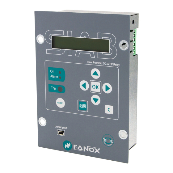
- Page 1 SIA-B Self & Dual Power Overcurrent Protection Relay INSTALLATION & COMMISSIONING GUIDE...
-
Page 2: Table Of Contents
Direct Access ........................ 15 7.3. Menus ..........................17 ..COMMISIONING ........................ 23 8.1. Thermal resistance ....................... 23 8.2. Self powering ........................ 25 8.3. Measurements ......................26 8.4. Protection functions ....................26 ..SIAB000B0010AA REGISTRY ..................30 www.fanox.com Installation_Guide_SIAB000B0010AA_Rev. 03 2 / 32... -
Page 3: Reception & Installation
In case some fault is detected, consider putting into quarantine period the relay and contact Fanox for further instructions. 1.2. Relay verification When relay is unpacked, please, take your time to confirm following checking list to be sure that everything is ok: •... -
Page 4: Powering The Relay Up
Serial Number In “General Settings” menu serial number of 8 digits can be checked (OK - ▼ - ▼ - ◄ - ▼ - ▼) • Firmware Version In “Firmware Version” menu (HOLD ▲) www.fanox.com Installation_Guide_SIAB000B0010AA_Rev. 03 4 / 32... - Page 5 OK: Action Checking Led ON Led ON activated ▼ Led ALARM Led ALARM activated ▼ Magnetic Indicator Trip Magnetic indicator ▼ Trip output Trip Output activated Skip from test menu www.fanox.com Installation_Guide_SIAB000B0010AA_Rev. 03 5 / 32...
-
Page 6: Relay Intallation
Do not use rechargeable batteries or other types of battery 5. Put on the battery cover and tighten the 2 screws. 6. Put the relay into the RMU again and tighten the 4 screws on the front to fix the relay. www.fanox.com Installation_Guide_SIAB000B0010AA_Rev. 03 6 / 32... -
Page 7: Relay Rear Part
Phase C current input for measurement and self-power Auxiliary power supply - Phase C current output for measurement and self-power ╧ Earthing screw 1.6. Connection diagram 1.6.1. Connection diagram. Three phase diagram, neutral internally calculated www.fanox.com Installation_Guide_SIAB000B0010AA_Rev. 03 7 / 32... -
Page 8: User Interface
There is a general trip without indicating the reason. 2.3. LED indicators The SIA-B front panel has two not configurable LEDs. By default, they show: ready (LED ON) and alarm (LED ALARM). Activated (Green LED blinking) if the relay is ready LED ON Activated (Red LED blinking) if an alarm occurs. -
Page 9: Setting-Up The Session: Password And Access Levels
Four passwords and their associated levels of access are set up when the equipment is configured using the SIcom program. By default, the equipment is programmed with the following passwords and their associated levels: PASSWORD ACCESS LEVEL 2222 3333 4444 5555 3. FUNCTIONAL DIAGRAM www.fanox.com Installation_Guide_SIAB000B0010AA_Rev. 03 9 / 32... -
Page 10: Technical Specifications
Defined time: 0.02 to 300 s (step 0.01 s) Dial: 0.05 to 1.25 (step 0.01) Curve, activation level 110% Curve, deactivation level 100% Defined time, activation level 100% Defined time, deactivation level 90% Instantaneous deactivation www.fanox.com Installation_Guide_SIAB000B0010AA_Rev. 03 10 / 32... - Page 11 Depth: 56.2 mm IP-54 when panel mounted 10 x Ismin or 2.85xIsmax: Continuously Thermal resistance 20 x Ismin or 5.7 x Ismax for 60 seconds 25 xIsmin or 7.14 x Ismax for 10 seconds. www.fanox.com Installation_Guide_SIAB000B0010AA_Rev. 03 11 / 32...
-
Page 12: Iec60255-151 Curves
4.1. IEC60255-151 Curves The SIA-B relay complies with the curves shown in standard IEC 60255-151: • Inverse Curve • Very Inverse Curve • Extremely Inverse Curve • Long time Inverse Curve There is a general mathematical equation that defines thetime in seconds as a function of the current: ... -
Page 13: Specific Current Transformers
5. SPECIFIC CURRENT TRANSFORMERS SIA-B relay requires specific CTs to achieve not only the line current measurement, but also the power to keep the relay switched on with tripping capability. Depending on the requirements there are the following possibilities: www.fanox.com... -
Page 14: Test Winding
SIA-B relay has been designed to work with these current levels. For this reason, it is not possible to do the same tests that are performed with relays that use standard CTs. -
Page 15: Flowchart
Led 1. 7.2. Direct Access Version The equipment versions menu can be accessed from the standby mode screen by holding “▲” key. Press the “C” key to return to the standby mode screen. www.fanox.com Installation_Guide_SIAB000B0010AA_Rev. 03 15 / 32... - Page 16 Press the “C” key to return to the standby mode screen. Communication parameters Hold “▼” key from standby menu to access to communication parameters menu. Press the “C” key to return to the standby mode screen. www.fanox.com Installation_Guide_SIAB000B0010AA_Rev. 03 16 / 32...
-
Page 17: Menus
7.3. Menus The information in SIA-B relay is organized through the following menus: Measurements States Settings Events Fault Report From standby screen press “OK” key to access to the fist menu “MEASUREMENTS” and press “▼” key to overview the rest of the menus in the relay To return to standby screen, press “C”... - Page 18 “OK” key to access the settings that belong to this group. Use the “▲” and “▼” keys to move through the different settings. information that appears underneath the setting name is its value. www.fanox.com Installation_Guide_SIAB000B0010AA_Rev. 03 18 / 32...
- Page 19 Use “▼” key to choose the wanted option (permission, curve type, time dial, tap or time delay) and press “OK” to access to its settings parameters. After inserting the password 5555 it will be possible to adjust the wanted value. www.fanox.com Installation_Guide_SIAB000B0010AA_Rev. 03 19 / 32...
- Page 20 Use “▼” key till SETTINGS menu appears. Pressing “◄” key it is accessed to GENERAL settings. Use “▼” key to overview the options and press “OK” when “CT type” option appears. After inserting the password 5555 it will be possible to adjust the wanted value www.fanox.com Installation_Guide_SIAB000B0010AA_Rev. 03 20 / 32...
- Page 21 GENERAL settings. Use “▼” key to overview the options and press “OK” when “Trip Voltage level” option appears. After inserting the password 5555 it will be possible to select the desired value. www.fanox.com Installation_Guide_SIAB000B0010AA_Rev. 03 21 / 32...
- Page 22 To visualize the rest events use “▼” key. How to delete the fault reports To delete the fault reports from the relay it is necessary to insert the password 5555 from the fault report menu. www.fanox.com Installation_Guide_SIAB000B0010AA_Rev. 03 22 / 32...
-
Page 23: Commisioning
RELAY WITHSTAND ENERGY GENERATION MODE SYSTEM CONNECTION WAVEFORM Phase- Single phase NOT APPLY P-N: Neutral Phase- P-P: Phase = 2x Three phase Phase- Balanced (120°) P-N Balanced: Neutral P-N Unbalanced: Un balanced (0°) = 3x www.fanox.com Installation_Guide_SIAB000B0010AA_Rev. 03 23 / 32... - Page 24 By following these recommendations, relay should pass commissioning test successfully. If commissioning test is performed not following these recommendations, manufacturer won’t be responsible for relay failure. www.fanox.com Installation_Guide_SIAB000B0010AA_Rev. 03 24 / 32...
-
Page 25: Self Powering
Adjust the Sverker current generator with HOLD 0.4xIsmin, and suddenly, inject it to the relay, as it would happened in real situation when circuit breaker is close, powering network line. The Led ON and LCD should be switched on: www.fanox.com Installation_Guide_SIAB000B0010AA_Rev. 03 25 / 32... -
Page 26: Measurements
Permission: YES. TAP: 1xIs=16 A Throretical tripping time: 2 (sec) Tripping time range: 1,9…2,1 s. The following information will be checked: Pick-up at 100% of the tap Trip output is activated Trip flag is activated www.fanox.com Installation_Guide_SIAB000B0010AA_Rev. 03 26 / 32... - Page 27 24-5%= 22.8 A Time: 19.69s +5% = 20.674s. Real admissible tripping time range: [14.573s…20.674s] The following information will be checked: Pick-up at 110% of the tap Trip output is activated Trip flag is activated www.fanox.com Installation_Guide_SIAB000B0010AA_Rev. 03 27 / 32...
- Page 28 20-5%= 19 A Time: 2.03s +5% = 2.1315s. Real admissible tripping time range: [1.216s…2.1315s] The following information will be checked: Pick-up at 110% of the tap Trip output is activated Trip flag is activated www.fanox.com Installation_Guide_SIAB000B0010AA_Rev. 03 28 / 32...
- Page 29 Take into account this time is calculated through an equation and this time depends on the injected current, so doing a ramp is possible but the theoretical tripping time will not be checked. www.fanox.com Installation_Guide_SIAB000B0010AA_Rev. 03 29 / 32...
-
Page 30: Siab000B0010Aa Registry
50 phase B: 50 Phase C: OK OK OK OK 51 phase A: 51 phase B: 51 phase C: OK OK OK OK OK OK www.fanox.com Installation_Guide_SIAB000B0010AA_Rev. 03 30 / 32... - Page 31 …………………………………………………………………………………………. …………………………………………………………………………………………. …………………………………………………………………………………………………… …………………………………………………………………………………………………… …………………………………………………………………………………………………… …………………………………………………………………………………………………… …………………………………………………………………………………………………… …………………………………………………………………………………………………… …………………………………………………………………………………………………… …………………………………………………………………………………………………… …………………………………………………………………………………………………… …………………………………………………………………………………………. …………………………………………………………………………………………. …………………………………………………………………………………………………… …………………………………………………………………………………………………… …………………………………………………………………………………………………… …………………………………………………………………………………………………… …………………………………………………………………………………………………… …………………………………………………………………………………………………… …………………………………………………………………………………………………… …………………………………………………………………………………………………… …………………………………………………………………………………………………… …………………………………………………………………………………………. …………………………………………………………………………………………. …………………………………………………………………………………………………… …………………………………………………………………………………………………… …………………………………………………………………………………………………… …………………………………………………………………………………………………… …………………………………………………………………………………………………… …………………………………………………………………………………………………… …………………………………………………………………………………………………… …………………………………………………………………………………………………… …………………………………………………………………………………………………… …………………………………………………………………………………………. www.fanox.com Installation_Guide_SIAB000B0010AA_Rev. 02 31 / 32...
- Page 32 Installation_Guide_SIAB000B0010AA_Rev. 03 32 / 32...
Need help?
Do you have a question about the SIA-B and is the answer not in the manual?
Questions and answers