FANOX SIA-B User Manual
Specific ct's self & dual powered overcurrent & earth fault protection relay
Hide thumbs
Also See for SIA-B:
- User manual (81 pages) ,
- Installation & commissioning manual (32 pages)

Related Manuals for FANOX SIA-B


Summary of Contents for FANOX SIA-B
- Page 1 SIA-B Specific CT´s Self & Dual Powered Overcurrent & Earth Fault Protection Relay USER´S MANUAL EN_FANOXTD_MANU_SIA_Ocefsecondarydist_SIAB-SPECIFIC-CT_R032.Docx...
-
Page 2: Table Of Contents
5.2. 50/51 Function. Inverse time phase overcurrent ................34 5.3. 50N Function. Instantaneous calculated neutral overcurrent ............. 35 5.4. 50/51N Function. Inverse time calculated neutral overcurrent ........... 36 5.5. Function TB. Trip block for the switch disconnector ..............36 www.fanox.com Rev. 32 2/114... - Page 3 8.6. SICom Communications program....................75 8.6.1. How to install SICOM Software ....................76 8.7. Setting up the session: password ....................77 8.8. MENUS .............................. 77 8.8.1. Standby mode screen ......................77 8.8.2. Accessing the menus ......................77 www.fanox.com Rev. 32 3/114...
- Page 4 9.6. Auxiliary power ..........................110 9.7. Front communications port ......................110 10. APPENDIX ............................110 10.1. Identification............................. 110 10.2. Checks .............................. 110 10.3. Test menu ............................110 10.4. Register of commissioning settings ....................111 10.5. Comments ............................112 www.fanox.com Rev. 32 4/114...
-
Page 5: Reception, Handling & Installation
It is necessary to inspect the equipment at the time it is delivered to ensure that the relays have not been damaged during transport. If any defect is found, the transport company and FANOX should be informed immediately. If the relays are not for immediate use, they should be returned to their original packaging. -
Page 6: Installation, Commissioning And Service
All electrical power sources should be removed before performing this operation to avoid the risk of electrical discharge. This product must be disposed of in a safe way. It should not be incinerated or brought into contact with water sources like rivers, lakes, etc… www.fanox.com Rev. 32 6/114... -
Page 7: Dimensions And Connection Diagrams
DIMENSIONS AND CONNECTION DIAGRAMS Vertical assembly Horizontal assembly 2.1. Frontal view Vertical model 2.1.1. Without internal commissioning battery With internal commissioning battery www.fanox.com Rev. 32 7/114... -
Page 8: Horizontal Model
Horizontal model 2.1.2. 2.2. Case dimensions Vertical model 2.2.1. Without internal commissioning battery With internal commissioning battery www.fanox.com Rev. 32 8/114... - Page 9 The dimensions are in mm. Cut-out pattern www.fanox.com Rev. 32 9/114...
-
Page 10: Horizontal Model
Horizontal model 2.2.2. The dimensions are in mm: (*) Digital outputs available depending on model www.fanox.com Rev. 32 10/114... -
Page 11: Striker Dimensions
Cut-out pattern 2.3. Striker dimensions 2.3.1. PRT-15 www.fanox.com Rev. 32 11/114... -
Page 12: Prt
2.3.2. 44,5 49,5 56,5 64,5 42,5 www.fanox.com Rev. 32 12/114... -
Page 13: Connection Diagram
2.4. Connection diagram Without signaling outputs 2.4.1. With signaling outputs 2.4.2. NOTE! STRIKER: 6 – 24 Vdc & <= 0.135 W·s www.fanox.com Rev. 32 13/114... -
Page 14: Terminals
External trip C3-C4 Phase B current output for measurement and self- Auxiliary power supply + power Phase C current input for measurement and self-power Auxiliary power supply - Phase C current output for measurement and self- power www.fanox.com Rev. 32 14/114... -
Page 15: Without Signaling Outputs And Rear Communication
Digital output 1 NC Phase C current output for measurement and self- Digital output 1 NO power Trip output + Digital 2 common output Trip output – Digital output 2 NC External trip Digital output 2 NO C3-C4 www.fanox.com Rev. 32 15/114... -
Page 16: Description
3.2. Description The SIA-B equipment is a protection relay designed for secondary distribution. One of its main characteristics is the necessity of using specific current transformers for measurement and power supply. The equipment starts-up from 0.8xIsmin single phase and 0.4xIsmin three phase current using specific CTs. - Page 17 The equipment has storage for up to 100 events, allowing any recorded incidents to be analyzed. All SIA-B models are equipped with a real-time clock (RTC) which permits registering all the events with a reliable timestamp. Current measurements are performed using RMS values. Specific current transformers (CTs) are used.
- Page 18 Events registered in the FRAM are maintained when there is a power fault, as it is a non-volatile memory. A maximum of 100 events can be stored. Fault reports registered in the FRAM are maintained when there is a power fault, as it is a non-volatile memory. A maximum of 4 fault reports can be stored. www.fanox.com Rev. 32 18/114...
-
Page 19: Functional Diagram
3.3. Functional Diagram www.fanox.com Rev. 32 19/114... -
Page 20: Selection & Ordering Codes
Trip (striker) + External trip input (49T) + 1 magnetic indicator + 2 Outputs Mechanics Vertical Assembly Horizontal Assembly Vertical Assembly with anticorrosive treatment Horizontal Assembly with anticorrosive treatment Languages English, Spanish and German English, Spanish and Turkish English, Spanish and French English, Spanish and Russian Adaptation www.fanox.com Rev. 32 20/114... -
Page 21: Specific Cts
3.5. Specific CTs SIA-B relay requires specific CTs to achieve the measurement and the power supply. Different mechanics are available to cover all the requirements: Epoxy Resin specific CT 3.5.1. Depending on the model selected, there are the following primary currents:... - Page 22 Cable diameter 3-33 (A) 5P80 50 mm 6-65 (A) 5P80 50 mm 6-65 (A) 10P80 50 mm 12-130 (A) 5P80 50 mm 25-260 (A) 5P80 50 mm 51-520 (A) 5P80 50 mm 102-1040 (A) 5P80 50 mm www.fanox.com Rev. 32 22/114...
- Page 23 Three transformers are needed, one per each phase. In the following picture, it is possible to see the label corresponding to CT016, where the connecting terminals are showed. Terminals: Primary Input Primary output Output for current measurement Input for current measurement B+ B- Test wiring terminals www.fanox.com Rev. 32 23/114...
- Page 24 • Dimensions: www.fanox.com Rev. 32 24/114...
-
Page 25: Taped Specific Ct
Class A Frequency 50/60 Hz Protection 5P80 Sec. cable-diameter 2.5 mm /500 mm Test Winding 0.288 A nominal Burden 0.05 VAs Dimesions 75x115x80 (ID x OD x W) (*) For other transformation ratios contact with Fanox www.fanox.com Rev. 32 25/114... - Page 26 Three transformers are needed, one per each phase. In the following picture, it is possible to see the label corresponding to CT16, where the connecting terminals are showed. Terminals: Primary Input Primary output Output for current measurement Input for current measurement Test wiring terminals www.fanox.com Rev. 32 26/114...
- Page 27 • Dimensions: Model CT16-5: . Model CT08-5: www.fanox.com Rev. 32 27/114...
-
Page 28: How To Select The Correct Ct
1. Power CT primary nominal current: It will be selected the CT with a range where this nominal current (In) is included: CT type In (Primary nominal current) CT008-5 3-33 (A) CT016-5 6-65 (A) CT016-10 CT032-5 12-130 (A) CT064-5 25-260 (A) CT128-5 51-520 (A) CT256-5 102-1040 (A) www.fanox.com Rev. 32 28/114... - Page 29 6-65 (A) CT016-10 32-112 (A) 12-130 (A) CT032-5 64-224 (A) 25-260 (A) CT064-5 128-448 (A) 51-520 (A) CT128-5 256-896 (A) 102-1040 (A) CT256-5 This setting appears in the relay in GENERAL SETTINGS menu as NOMINAL CURRENT www.fanox.com Rev. 32 29/114...
- Page 30 To choose the correct Is setting in this case, it will be selected the most similar value to the primary nominal current defined in the first step (In). POWER CT SELECTION SIA-B GENERAL SETTINGS TRANSFORMER IN RANGE MODEL CT TYPE...
- Page 31 25<In <64 64<In <224 224 A 224<In <260 51-520 A CT128-5 CT128 128 A 51<In <128 128<In <448 448 A 448<In <520 102-1040 A CT256-5 CT256 256 A 102<In <256 256<In <896 896 A 896<In <1040 www.fanox.com Rev. 27 31/114...
-
Page 32: Test Winding
TEST WINDING SIA-B relay has been designed to work with these current levels. For this reason it is not possible doing the same tests that are performed with relays that use standard CTs. Both CTs (Resin or taped) can be used to carry the test winding out. - Page 33 Taped specific CTs In the case of SIA-B, the necessary current to perform the testing is provided through the no conventional current transformers. These CTs have a pass-through hole (from P1 to P2 in the picture blow) for primary current measurement, 2 terminals (S1 and S2 in the picture below) for secondary...
-
Page 34: Protection Functions
IEEE Extremely inverse If the option "Defined time" is selected for the curve setting, the unit behaves like an instantaneous overcurrent unit. In this case, the unit Time Delay is set by the parameter "Time Delay". www.fanox.com Rev. 32 34/114... -
Page 35: Function. Instantaneous Calculated Neutral Overcurrent
The function activates at 100% of the pre-set input and deactivates at 90%. The reset is instantaneous. The accuracy of the Time Delay is equal to the pre-set time ±40ms or ±0.5% (greater of both). www.fanox.com Rev. 32 35/114... -
Page 36: 50/51N Function. Inverse Time Calculated Neutral Overcurrent
Group Description Minimum Maximum Step Unit Default Trip block protection for the switchgear Function Enable Yes/No Current Current 1.50 20.00 0.01 7.00 www.fanox.com Rev. 32 36/114... -
Page 37: Function. Thermal Image Protection
This protection function is adjusted by setting five different parameters: Function Description Minimum Maximum Pitch Unit Default Thermal image protection function Function Yes/No Enable Current Tap 0.10 2.40 0.01 1.20 ζ heating ζ cooling ζ heating Alarm www.fanox.com Rev. 32 37/114... - Page 38 Thermal image protection trip bit is active when the measurement of the thermal image is over 100% and it is reset when the measurement of the thermal image is under the adjusted alarm level. www.fanox.com Rev. 32 38/114...
- Page 39 5.6.3. Thermal image measurement display. Reset Thermal image measurement can be displayed on Measurement menu. 5.6.4. Thermal protection curves This is the thermal curve for ζ = 3 minutes. www.fanox.com Rev. 32 39/114...
-
Page 40: External Trip
The serial number is only a reading setting. The rest of the settings can be changed either from the HMI or through communications. Any change of set values will restart all functions, irrespective they are activated or not. www.fanox.com Rev. 32 40/114... -
Page 41: Settings Groups
▪ Changing active group. In general settings menu, there is an option to establish which group is active. 5.10. IEC60255-151 Curves The SIA-B relay complies with the curves shown in standard IEC60255-151: • Inverse Curve • Very Inverse Curve •... - Page 42 Rev. 32 42/114...
- Page 43 Rev. 32 43/114...
- Page 44 Rev. 32 44/114...
- Page 45 Rev. 32 45/114...
-
Page 46: Ieee Curves
Very Inverse 19,61 0,491 Inverse 0.0515 0.02 0,114 The curve can move from its axis using the TD time selection device, which the user can adjust. is the initial operating current, set by the user. adjusted www.fanox.com Rev. 32 46/114... - Page 47 Rev. 32 47/114...
- Page 48 Rev. 32 48/114...
- Page 49 Rev. 32 49/114...
-
Page 50: Monitoring And Control
HMI, you have to go to the events menu and press and hold the "RESET" key until the number of events reads 1, and this event is registered as "Events deleted". To delete the events using communications, use the corresponding "delete events" command. To delete the events, it is necessary to enter a password. www.fanox.com Rev. 32 50/114... - Page 51 Activation/Deactivation bit-11 EEPROM error EEPROM error Activation/Deactivation bit-12 EEPROM changed EEPROM changed Activation/Deactivation bit-13 Events error Events error Activation/Deactivation Bit-15 Reset Reset Activation/Deactivation bit-16 Pickup (*) Events deleted Activation Fault report Activation Number of fault report www.fanox.com Rev. 32 51/114...
- Page 52 50 Phase B Trip 50 Phase B Trip Activation/Deactivation Phase B current bit-10 50 Phase C Trip 50 Phase C Trip Activation/Deactivation Phase C current bit-11 50 Phase Trip 50 Phase Trip Activation/Deactivation Maximum current www.fanox.com Rev. 32 52/114...
- Page 53 Phase C block Activation/Deactivation Phase C current bit-03 Phase block Phase block Activation/Deactivation Thermal image bit-04 49 Alarm 49 Alarm Activation/Deactivation Thermal image 49 (*) bit-12 49 Trip 49 Trip Activation/Deactivation Thermal image (*) Optional depending on model www.fanox.com Rev. 32 53/114...
-
Page 54: Fault Reports
This clock can be synchronized by any of the two following procedures: • From the HMI. In this case the date and time can be entered via the keyboard. The relay will store the new event indicating that it has been synchronized. www.fanox.com Rev. 32 54/114... -
Page 55: Self-Diagnosis
2 situations appear on the main screen (EEPROM ERROR or EVENTS ERROR), the relay should be replaced and it will be necessary to contact Fanox. On the other hand, “Default settings” means that the equipment is operating under factory settings, being all protection functions disabled. -
Page 56: Programmable Logic Control & Digital Outputs
HMI or from SICom software. For each output, there is a LOGICAL GATE. It can perform a logical operation up to 4 binary states to obtain other binary result. In V3 of the PLC the LOGICAL GATES that are supported by SIA-B are:... -
Page 57: Commands
6.9. Test Menu The SIA-B equipment has a test menu that can be used to check the operation of the signalling components and the outputs. It is important to point out that the operation of the outputs is not guaranteed if the test is performed with the battery. -
Page 58: Power Supply
The continuous operation of SIA-B is guaranteed with the levels of self-power (0,4 x Ismin three phase current or 0.8xIsmin one phase) and the auxiliary power supply 230Vac/110Vac. -
Page 59: Battery Power: 5 V, With A Kitcom Adaptor
When the equipment is being powered from a 5 V battery, it is capable of functioning for 4 hours. The relay can also be powered through a USB cable connected directly to the laptop or through a conventional powerbank. www.fanox.com Rev. 32 59/114... -
Page 60: Commisioning Battery
When this key is pressed an event of Measure Error is generated. This event is originated because once this key is pressed, only one microprocessor is activated and there is no communication between the microprocessors. www.fanox.com Rev. 32 60/114... - Page 61 Unscrew the 4 screws on the front of the relay to extract it from the RMU. Access to the rear side of the relay. Unscrew the 2 screws to remove the cover from the battery compartment. www.fanox.com Rev. 32 61/114...
- Page 62 Do not disassemble the battery. • Do not heat the battery above 100ºC (212ºF) • Do not throw the battery into fire or water. Failure to follow these instructions can result in death, serious injury, or equipment damage. www.fanox.com Rev. 32 62/114...
-
Page 63: Switch On To Fault Characteristic (Sotf)
6.11. Switch on to fault characteristic (SOTF). SIA-B is an electronic device, which provides a starting up time (time from equipment activation to operational capacity). Logically, it is a desirable to have a minimum time for the starting up the equipment. - Page 64 SIA-B TRIP ONTO FAULT CT16-5 1400 1200 1000 0,4xIn 0,5xIn 0,8xIn 1xIn 1,5xIn 2xIn 2,5xIn 3xIn 3,5xIn 4xIn 4,5xIn 5xIn Three Phase 12 Vdc (ms) Single Phase 12 Vdc (ms) 1100 Three Phase 17 Vdc (ms) Single Phase 17 Vdc (ms)
-
Page 65: Opening Mechanism: Striker
Striker activation The activation of the SIA-B trip output means that a capacitor has discharged on the output terminals. This discharge of energy is sufficient to activate a striker that mechanically acts on a mechanism to open the current circuit. - Page 66 16 Ohm Protection class IP00 Due to the existing variety in the market, it is important to check the voltage and the necessary energy for its activation. If you have any doubt, please contact with Fanox. www.fanox.com Rev. 32 66/114...
-
Page 67: Technical Specifications And Standards
Curve, deactivation level 100% Defined time, activation level 100% Defined time, deactivation level 90% Instantaneous deactivation Timing accuracy: ± 40 ms or ± 5% (greater of both, considering the operating time is influenced by the used CT) www.fanox.com Rev. 32 67/114... - Page 68 24 Vdc; 135 mJ (activation of the striker or low powered coil) Signalling outputs (*) 2 configurable outputs (output 2 and output 3): 220 Vdc – 8 A (30 W max) 250 Vac – 8 A (62,5 VA max) Frequency 50/60Hz www.fanox.com Rev. 32 68/114...
-
Page 69: Thermal Resistance
• 10 x Ismin or 2.85 x Ismax: continuously. • 20 x Ismin or 5.7 x Ismax for 60 seconds. • 25 x Ismin or 7.14 x Ismax for 10 seconds. www.fanox.com Rev. 32 69/114... -
Page 70: Standards
1.12. 100KHz damped oscillatory IEC 61000-4-18 Class 3, Repetition frequency 40Hz, Duration waves of each application 3s. Common mode: ±2.5kV. Differential mode: ±1kV 1.13. Pulse magnetic fields IEC 61000-4-9 Field strenght 1000 A/m, Cadence between pulses 40s. www.fanox.com Rev. 32 70/114... - Page 71 Dry Heat Operation Bb, +70ºC, 72h Dry Heat transport & Storage Bd, +85ºC, 72h 6.3 Change of temperature IEC 60068-2-14 Change of Temperature Nb, Upper temp +70ºC, Lower temp -25ºC, 5 cycles, Exposure time 3h, Transfer time 2 min. www.fanox.com Rev. 32 71/114...
- Page 72 Declared on manual, without damage for continuous operation 8.4. VT Input short time overload IEC 60255-27 Declared on manual, without damage for 10s short time overloading 9. Enclosure protection 60255-27 IP-54 IEC 60529 Quality Management System ISO 9001:2008 www.fanox.com Rev. 32 72/114...
-
Page 73: Communication And Hmi
8.2. Rear communication: RS485 An option exists to fit the SIA-B with a rear communications port RS485, which must be specified when the model is selected. The RS485 port output has two terminals (+,-), located on the rear of the equipment. The protocol that is used is Modbus RTU (19200 -8bit –... -
Page 74: Bistable Magnetic Indicators
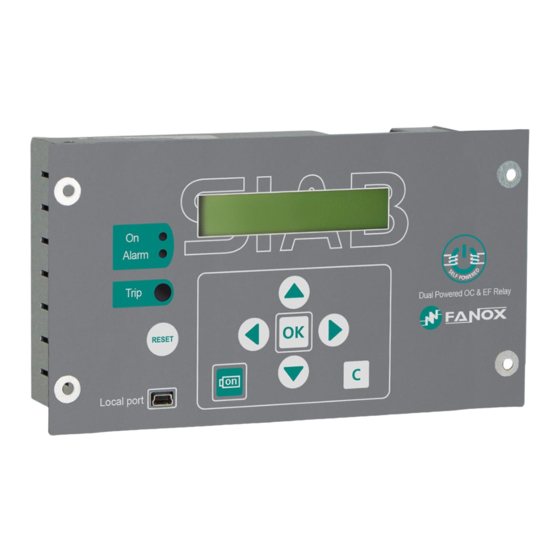
8.4. LED indicators The SIA-B front panel has two LED pilot lights to show if the equipment is ON (LED ON) and if there has been an alarm (LED ALARM). The LEDs are switched off when the equipment is not... -
Page 75: Lcd And Keypad
8.5. LCD and keypad The front of the SIA-B relay is fitted with an alphanumeric LCD screen, measuring 20x2. This screen provides the user with access to read information about the settings parameters, measurements, state and events. All of this information is arranged in a system of menus. -
Page 76: How To Install Sicom Software
How to install SICOM Software 8.6.1. To install the SICom it is necessary the following link: http://fanox.blob.core.windows.net/sicom/publish.htm The link will open the next screen, where key “install” must be pressed: The necessary drivers depending on the operative system can be downloaded from this page. -
Page 77: Setting Up The Session: Password
▼ are used to increase or decrease the value. If an invalid value is entered during the process, the “C” key can be used to delete it. The navigation through the menus is described as graphically as possible below. www.fanox.com Rev. 32 77/114... -
Page 78: Date-Time Menu
The contrast menu can be accessed from the standby mode screen by pressing the “◄” key. Contrast level can be changed using the “▲” and “▼” keys. Press the “C” key to return to the standby mode screen. ◄ Contrast: SIAB00011000AA 0.00 0.00 0.00 0.00 hold www.fanox.com Rev. 32 78/114... -
Page 79: Fault Report
From the "sleep" mode screen, press the “◄” key to access the fault report. Use the “▲” and “▼” keys to find the fault report and pressing “OK” the data of this fault report can be read. 50 Trip SIAB00011000AA 04/11/2013 01:43:25 0.00 0.00 0.00 0.00 04/11/2013 01:43:25000 _I 50 Trip www.fanox.com Rev. 32 79/114... -
Page 80: Test Menu
“OK” to access the components that can be tested. TEST MENU y/n? ◄ ▼ ► without protection! OK hold Set Password -> 0 Set Password ◄▼▲► -> 5555 TEST MENU Led1: not activated Led1: <<ACTIVATED>> Led2: ▲▼ not activated www.fanox.com Rev. 32 80/114... - Page 81 Led2: <<ACTIVATED>> Trip bistable: ▲▼ not activated Trip bistable: <<ACTIVATED>> Trip Output: ▲▼ not activated Trip Output: <<ACTIVATED>> Output 2: ▲▼ not activated Output 2: <<ACTIVATED>> Output 3: ▲▼ not activated Output 3: <<ACTIVATED>> www.fanox.com Rev. 32 81/114...
-
Page 82: Functions Menu
8.8.9. Functions Menu The SIA-B relay menu is split up into 6 main parts: • Measurements. • State. • Settings. • Events. • Commands • Fault Reports SIAB00001000AA SIAB00001000AA MEASUREMENTS 0.00 0.00 0.00 0.00 0.00 0.00 0.00 0.00 ▲▼ STATES SETTINGS GEN... -
Page 83: Measurements Menu
0.00 0.00 0.00 0.00 ↓ ↑ MEASUREMENTS = 0.00 A ↓ = 0.00 *A ▲▼ = 0.00 A ▲▼ = 0.00 A ▲▼ = 0.00 A ▲▼ IMax = 0.00 A ▲▼ = 10 www.fanox.com Rev. 32 83/114... -
Page 84: States Menu
↑ STATES Sta. GENERAL ↓ Trip: Sta. GENERAL not activated External Trip: ▲▼ not activated Error Trip power: ▲▼ not activated 50 Hz: ▲▼ <<ACTIVATED>> Trip Block Enab.: ▲▼ not activated Error Measure: ▲▼ not activated www.fanox.com Rev. 32 84/114... - Page 85 Not activated Set Date/Time: ▲▼ not activated Local Act.: ▲▼ not activated Factory Settings: ▲▼ not activated Error Eeprom: ▲▼ not activated Eeprom changed: ▲▼ not activated Error Events: ▲▼ not activated Reset: ▲▼ not activated www.fanox.com Rev. 32 85/114...
- Page 86 ▲▼ not activated Sta. Remote COM. Sta. Remote COM. ↑ STATES ▲▼ ↓ Remote COM: not activated Reset TI: ▲▼ not activated ↑ STATES ▲▼ Sta. 50 ↓ Phase A Pickup: C Sta. 50 not activated www.fanox.com Rev. 32 86/114...
- Page 87 Phase C Pickup: ▲▼ not activated Phase Pickup: ▲▼ not activated Phase A Trip: ▲▼ not activated Phase B Trip: ▲▼ not activated Phase C Trip: ▲▼ not activated Phase Trip: ▲▼ not activated www.fanox.com Rev. 32 87/114...
- Page 88 Phase B Pickup: ▲▼ not activated Phase C Pickup: ▲▼ not activated Phase Pickup: ▲▼ not activated Phase A Trip: ▲▼ not activated Phase B Trip: ▲▼ not activated Phase C Trip: ▲▼ not activated www.fanox.com Rev. 32 88/114...
- Page 89 Ground Trip: ▲▼ not activated ↑ STATES ▲▼ Sta. 51N ↓ Ground Pickup: C Sta. 51N not activated Ground Trip: ▲▼ not activated ↑ STATES ▲▼ Sta. INPUTS ↓ Input 1: C Sta. INPUTS not activated www.fanox.com Rev. 32 89/114...
- Page 90 Sta. OUTPUTS ↓ Trip Output: C Sta. OUTPUTS not activated Output 2: ▲▼ not activated Output 3: not activated ↑ Sta. LEDS STATES ↓ Led1: Sta. LEDS not activated Led2: ▲▼ not activated Bistable: ▲▼ not activated www.fanox.com Rev. 32 90/114...
- Page 91 Sta. TRIP BLOCK not activated Phase B Block: ▲▼ not activated Phase C Block: ▲▼ not activated Phase Block: ▲▼ not activated ↑ STATES ▲▼ Sta. 49 ↓ Alarm: Sta. 49 not activated Trip: ▲▼ not activated www.fanox.com Rev. 32 91/114...
-
Page 92: Settings Menu
If it is necessary to change one of the password characters or numbers due to an error, press "C" to delete it. Press "OK” to validate the password. The method for navigating through the settings menu and the sequence to follow to change a setting are shown graphically below: www.fanox.com Rev. 32 92/114... - Page 93 ↓ ↓ Select table ↑ ▲▼ ↓ GEN SETTINGS ↑ Sett(1) 50 COM → ↓ Function Enable Sett(1) 50 Set Password Function Enable -> 0 Set Password ◄▼▲► -> 5555 Function Enable NO -> NO www.fanox.com Rev. 32 93/114...
- Page 94 NO > YES y/n SETTING CHANGED Function Enable Function Enable Current Tap ▲▼ 1.00 xIn Time Delay ▲▼ 0.02 s SETTINGS ↑ ▲▼ Sett(1) 51 COM → ↓ Function Enable Sett(1) 51 Curve type ▲▼ Def Tim www.fanox.com Rev. 32 94/114...
- Page 95 ↑ SETTINGS ▲▼ Sett(1) 50N COM → ↓ Function Enable Sett(1) 50N Current Tap 1.00 xIn(1.00) ▲▼ Time Delay 0.2 s ▲▼ ↑ SETTINGS ▲▼ Sett(1) 51N ▲▼ COM → ↓ Function Enable Sett(1) 51N www.fanox.com Rev. 32 95/114...
- Page 96 Time Delay 0.2 s ▲▼ SETTINGS ↑ ▲▼ Sett(1) TRIP BLOCK COM → ↓ Function Enable Sett(1) TRIP BLOCK Set Password Function Enable -> 0 Set Password ◄▼▲► -> 5555 Function Enable NO -> NO www.fanox.com Rev. 32 96/114...
- Page 97 NO > YES y/n SETTING CHANGED Function Enable Function Enable Current Tap ▲▼ 1.00 xIn Time delay 0.20 s ↑ ▲▼ Sett(1) 49 SETTINGS GEN ↓ Function Enable Sett(1) 49 Current Tap ▲▼ 0.20 xIn www.fanox.com Rev. 32 97/114...
- Page 98 ▲▼ To access the general settings from the “SETTINGS” menus, press “◄” SETTINGS GEN Identification ↑ ◄ SIAB text COM → ↓ Frequency ▲▼ 50Hz Serial Number ▲▼ Language ▲▼ ENG. Active Settings Group ▲▼ www.fanox.com Rev. 32 98/114...
- Page 99 Nominal current ▲▼ CT type ▲▼ CT008 Local COM Address ▲▼ Remote COM Address ▲▼ Remote COM Baudrate ▲▼ 19200 Password ▲▼ **** ► To access the communication parameters from the “SETTINGS” menus, press “ ” www.fanox.com Rev. 32 99/114...
- Page 100 SETTINGS GEN ↑ ► COM→ ↓ Remote COM Address ▲▼ Remote COM Baudrate ▲▼ 19200 Password ▲▼ **** Identification ▲▼ SIAB Text Frequency ▲▼ 50Hz Serial Number ▲▼ Language ▲▼ ENG. Active Settings Group ▲▼ www.fanox.com Rev. 32 100/114...
- Page 101 Trip Voltage Level ▲▼ 17 Vdc Nominal current ▲▼ CT type ▲▼ CT008 www.fanox.com Rev. 32 101/114...
-
Page 102: Events Menu
4/5: ▲▼ ┐ 52 Open Error ┐ 52 Open Error Set Password EVENTS ↑ RESET -> 0 There are 5 ↓ Set Password ◄▼▲► -> 5555 Confirm Erased Events y/n? EVENTS ↑ There are 1 ↓ www.fanox.com Rev. 32 102/114... - Page 103 Position of the event within the list of events • Events generated by a state activation or reset • Associated measurement (if it has one) Associated measurement Time Date 01/01/00 00:54:18600 1/99 measurement Events erased Events erased Activated or Not activated Event description www.fanox.com Rev. 32 103/114...
-
Page 104: Commands Menu
Press the "OK" key to perform a command, and press the "OK" key again to confirm the command. SIAB00001000AA ↑ COMMANDS 0.00 0.00 0.00 0.00 ↓ EXECUTE COMMAND ↑ COMMANDS Reset TI ↓ CONFIRM COMMAND EXECUTE COMMAND Reset TI Reset TI ↑ COMMANDS ↓ www.fanox.com Rev. 32 104/114... -
Page 105: Fault Reports
To delete the fault reports, position the cursor over the fault report menu and press and hold the "RESET" key, until password is requested. Introduce the password and press OK until there is a massage informing “fault reports erased”." www.fanox.com Rev. 32... -
Page 106: Plc And Outputs Configuration Menu
Phase B Pickup: ▲▼ not activated Phase B Pickup: > TripOutput y/n? Phase B Pickup: Phase B Pickup: ▲▼ ◄ Sta. 50 > Output2 y/n? > Output 2 y/n? Configuration Processing... Con 1/4 Output 2 Phase B Pickup www.fanox.com Rev. 32 106/114... - Page 107 Output 2 y/n? ◄ Phase B Pickup: § > Output 2 y/n? ◄ Phase B Pickup: > $ Output 2 y/n? ◄ Phase B Pickup: ◄ > Output 2 y/n? Phase B Pickup: ◄ > Output 2 y/n? www.fanox.com Rev. 32 107/114...
- Page 108 1 to 4. The “▲” and “▼” keys can be used in this menu to browse all of the states (up to 4) that are associated with a Press and hold the “RESET” key while viewing any of the instantaneous states associated with the output and its index physical output. number from 1 to 4 to remove the association with the physical output. www.fanox.com Rev. 32 108/114...
-
Page 109: Commissioning
• FANOX recommends the use of the KITCOM accessory with a battery in the front port. This additional energy source allows the relay to be monitored and the trip to function without the need for self-power in any breakdown situation. -
Page 110: Auxiliary Power
9.7. Front communications port To perform this test, connect a PC with the SICom software program to the SIA-B relay, and check that there are no communication errors. It is important to check communications port (COM) which is assign to USB. -
Page 111: Register Of Commissioning Settings
Current Tap....……………… x In Inverse Very Inverse Ext. Inverse LT Inverse IEC curve type IEEE curve type Inverse Very Inverse Ext. Inverse Def. Time Time Dial (TMS) ……....………… Time Delay…..…..……..s www.fanox.com Rev. 32 111/114... -
Page 112: Comments
In 10.5. Comments …………….....……………………………………………………………………………..… …………….....……………………………………………………………………………..… ……………....……………………………………………………………………………..…. …………….....……………………………………………………………………………..… …………….....……………………………………………………………………………..… …………….....……………………………………………………………………………..… …………….....……………………………………………………………………………..… …………….....……………………………………………………………………………..… …………….....……………………………………………………………………………..… …………….....……………………………………………………………………………..… …………….....……………………………………………………………………………..… …………….....……………………………………………………………………………..… …………….....……………………………………………………………………………..… …………….....……………………………………………………………………………..… …………….....……………………………………………………………………………..… …………….....……………………………………………………………………………..… …………….....……………………………………………………………………………..… …………….....……………………………………………………………………………..… …………….....……………………………………………………………………………..… …………….....……………………………………………………………………………..… …………….....……………………………………………………………………………..… …………….....……………………………………………………………………………..… Person in charge of commissioning………..……..…………..Date……….....… Maintenance performed on the………………….. by ………..………………………………….. www.fanox.com Rev. 32 112/114... - Page 113 NOTES: ……………………………………………………………………………………………………..… ……………………………………………………………………………………………………..… ……………………………………………………………………………………………………..… ……………………………………………………………………………………………………..… ……………………………………………………………………………………………………..… ……………………………………………………………………………………………………..… ……………………………………………………………………………………………………..… ……………………………………………………………………………………………………..… ……………………………………………………………………………………………………..… ……………………………………………………………………………………………………..… ……………………………………………………………………………………………………..… ……………………………………………………………………………………………………..… ……………………………………………………………………………………………………..… ……………………………………………………………………………………………………..… ……………………………………………………………………………………………………..… ……………………………………………………………………………………………………..… ……………………………………………………………………………………………………..… ……………………………………………………………………………………………………..… ……………………………………………………………………………………………………..… ……………………………………………………………………………………………………..… ……………………………………………………………………………………………………..… ……………………………………………………………………………………………………..… ……………………………………………………………………………………………………..… ……………………………………………………………………………………………………..… ……………………………………………………………………………………………………..… ……………………………………………………………………………………………………..… www.fanox.com Rev. 32 113/114...
- Page 114 Rev. 32 114/114...
Need help?
Do you have a question about the SIA-B and is the answer not in the manual?
Questions and answers