Table of Contents
Advertisement
Quick Links
Advertisement
Table of Contents

Related Manuals for FANOX SIL-G


Summary of Contents for FANOX SIL-G
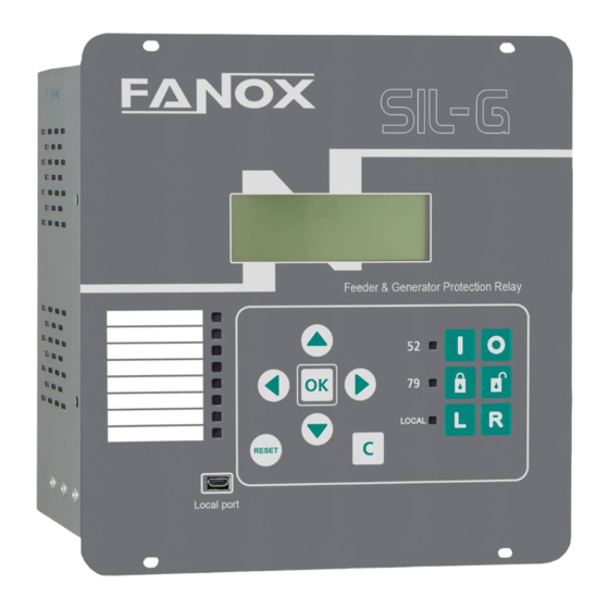
- Page 1 SIL-G Feeder Relay USER’S MANUAL USER’S MANUAL...
-
Page 2: Table Of Contents
Thermal image with memory .................. 45 4.10.3 Thermal image measurement display. Reset............45 4.10.4 Thermal protection curves ..................46 4.11 Function 37. Instantaneous phase undercurrent ..........47 4.12 Function AFD. Arc Flash Detection ................ 47 VOLTAGE PROTECTION FUNCTIONS ..............50 www.fanox.com Rev.01 2/151... - Page 3 Maximum openings in a time frame ............... 75 GENERAL SETTINGS....................77 Measurements......................77 DFR .......................... 78 General ........................78 USB communication ....................78 WiFi communication ....................78 Remote communications ..................80 9.6.1 Model SILGxxxxxxAxxx / Model SILGxxxxxxFxxx..........80 SETTINGS GROUPS....................81 AVALIABLE CURVES....................82 www.fanox.com Rev.01 3/151...
- Page 4 14.2 Remote communications ports................144 14.3 LCD and keypad ....................144 14.4 SICom Communications program ................ 145 14.5 How to install SICOM Software ................145 14.6 Setting up the session: Passwords and access levels ........147 www.fanox.com Rev.01 4/151...
-
Page 5: Reception, Handling, Installation
It is necessary to inspect the equipment at the time it is delivered to ensure that the relays have not been damaged during transport. If any defect is found, the transport company and FANOX should be informed immediately. If the relays are not for immediate use, they should be returned to their original packaging. -
Page 6: Installation, Commissioning And Service
This product must be disposed of in a safe way. It should not be incinerated or brought into contact with water sources like rivers, lakes, etc. www.fanox.com Rev.01 6/151... -
Page 7: Dimensions And Connection Diagrams
2 DIMENSIONS AND CONNECTION DIAGRAMS 2.1 Equipment front view 2.2 Equipment dimensions www.fanox.com Rev.01 7/151... -
Page 8: Connection Diagrams
2.3 Connection diagrams 2.3.1 Analog current connections www.fanox.com Rev.01 8/151... -
Page 9: Analog Voltage Connections
2.3.2 Analog voltage connections In SIL-G relay it is important to consider the connection type is configurable by the user. Depending on model the following options are available: SIL-Gxxxx0xxxxx (without ANSI 25): (Un = 100-130 V) 3 VT Phase-Neutral configuration... - Page 10 3 VT configuration (phase-neutral) www.fanox.com Rev.01 10/151...
- Page 11 3 VT configuration (phase-neutral) + residual voltage www.fanox.com Rev.01 11/151...
- Page 12 3VT configuration (phase-phase) + residual voltage www.fanox.com Rev.01 12/151...
- Page 13 2VT configuration (phase-phase) + residual voltage www.fanox.com Rev.01 13/151...
- Page 14 3 VT configuration (phase-neutral) + phase B line voltage www.fanox.com Rev.01 14/151...
- Page 15 Connecting the relay directly to Low Voltage line (Un = 260-480 V) Phase-neutral connection www.fanox.com Rev.01 15/151...
- Page 16 Phase-phase connection NOTE. Voltage Neutral protections (50N, 67N and 59N), voltage ground protections (50G, 67G and 59G) and voltage sequence protection (47) are not available with this configuration. www.fanox.com Rev.01 16/151...
-
Page 17: Terminals
Digital output 1 NC C13-C14 Digital output 2 NO C15-C16 Digital output 3 NO C17-C18 Digital output 4 NO C19-C20 Digital output 5 NO C21-C22 Digital output 6 NO C23-C24 Digital output 7 NO C25-C26 RS-485 connections www.fanox.com Rev.01 17/151... -
Page 18: Silgxxxxxaaxxx
Digital output 1 NC C13-C14 Digital output 2 NO C15-C16 Digital output 3 NO C17-C18 Digital output 4 NO C19-C20 Digital output 5 NO C21-C22 Digital output 6 NO C23-C24 Digital output 7 NO C25-C26 RS-485 connections www.fanox.com Rev.01 18/151... -
Page 19: Silgxxxxxa7Xxx
Digital output 8 NO D23-D24 Digital input 15 – Common of digital input 15 E21-E22 Digital output 9 NO D25-D26 Digital input 16 – Common of digital input 16 E23-E24 Digital output 10 NO E25-E26 Digital output 11 NO www.fanox.com Rev.01 19/151... -
Page 20: Description
FANOX has developed the SIL family to carry out this function. The SIL-G relay is designed to protect a feeder system using current and voltage functions. It is designed to use a circuit breaker as a cut-off component. - Page 21 Allows circuit breaker opening and closing commands to be given from the HMI (using different keys) and through local and remote communications The following measurements are provided by the SIL-G equipment: Phase currents, neutral (measured and calculated), maximum current, positive sequence current and negative sequence current.
- Page 22 Bock/Unblock 79. Used to block and unblock the recloser. • Local/Remote Control. Used to forbid/allow remote communications. The SIL-G has 11 front-mounted LEDs, 3 with fixed functions and 8 can be configured. The LEDs with fixed functions are: • Status of the circuit breaker.
- Page 23 Thanks to the protection functions that are available, its user-friendly interface, its reduced maintenance requirements and simple integration, the SIL-G is an accurate and practical solution for protecting a feeder system. SIL-G offers protection against earth faults that is sufficiently sensitive for use with electrical systems with a low earth failure current (it can be adjusted to 0.01 times the rated current so...
- Page 24 ✓ Up to 4 attempts. Synchro check 1 (Optional) 74TCS Trip Circuit supervision 60CTS Current Transformer Supervision 60VTS Voltage Transformer Supervision 50BF Breaker failure monitoring Second harmonic blocking Cold Load Pick-up Circuit breaker monitoring ✓ Trip output lockout with PLC ✓ www.fanox.com Rev.01 24/151...
- Page 25 TCP (selectable by general settings) + IRIG-B • WiFi + 2 rear ports: 1 Fiber Optic port: HSR – IEC61850 + 1 Ethernet port (RJ45): Modbus TCP and DNP 3.0 TCP (selectable by general settings) + IRIG-B www.fanox.com Rev.01 25/151...
- Page 26 ✓ 2160 records Alarms Panel ✓ 32 alarms Real Time Clock (RTC 1 millisecond) ✓ IRIG-B synchronism ✓ (Optional) Test menu ✓ Self-diagnostic ✓ Settings Group Using keys Using configurable inputs 4 settings group Using communications Mechanics www.fanox.com Rev.01 26/151...
-
Page 27: Functional Diagram
Dimensions 175x175x150 3.3 Functional diagram www.fanox.com Rev.01 27/151... - Page 28 Rev.01 28/151...
-
Page 29: Selection & Ordering Codes
3.4 Selection & Ordering codes Not all combinations are possible. Please, confirm with Fanox chosen model. www.fanox.com Rev.01 29/151... -
Page 30: Phase Ct And Neutral Ct Selection
3.5 Phase CT and neutral CT selection SIL-G measures from 0.01 times the nominal current to 30 times the nominal current. The following table shows a summary of the phase and neutral CT combinations: Model Phase range SIL-G00 0.05-150 A SIL-G00 0.01-30 A... -
Page 31: Function Sotf. Switch On To Fault
Curve Type IEC Standard Inverse Time Dial (TMS) 0.05 25.00 0.01 1.00 Current Tap 0.010 20.000 0.001 5.000 Time Delay 0.000 300.000 0.001 0.200 Directionality No/Forward/Reverse Polarization voltage 0.08 2.00 0.01 0.50 Operating angle degrees Halfcone angle degrees www.fanox.com Rev.01 31/151... - Page 32 If the directionality option is not activated, the 67 function behaves like a 51/50 function. The actuation time starts when the following conditions are met simultaneously: Phase current higher than adjusted. www.fanox.com Rev.01 32/151...
- Page 33 UAB Voltage The following figure shows a graphic representation of the directional actuation zone, adjusted with an operating angle of 90° and a half-cone angle of 60°. FORWARD OPERATING ANGLE = 90º HALF-CONE ANGLE = 60º V polarization www.fanox.com Rev.01 33/151...
-
Page 34: Function 50G. Instantaneous Measured Neutral Overcurrent
The function activates at 100% of the preset input and deactivates at 95%. The reset is instantaneous. The accuracy of the Time Delay is equal to the set time delay ±35ms or ±0.5% (whichever is greater). www.fanox.com Rev.01 34/151... -
Page 35: Function 50N. Instantaneous Calculated Neutral Overcurrent
Operating angle degrees Half-cone angle degrees “Un” will be Nominal V. P-P setting/ √ �� (available in general settings) regardless the VT connection type. Definite time and 8 curves are included to be selected by the user: www.fanox.com Rev.01 35/151... - Page 36 If the directionality option is not activated, the 67G function behaves like a 51G/50G function. The actuation time starts when the following conditions are met simultaneously: Phase current higher than adjusted. www.fanox.com Rev.01 36/151...
- Page 37 Vr if available or 3V0 Voltage For this function, depending on the VT connection, the polarization voltage will be the Residual Voltage (Vr) when available or the calculated 3V0 when there is no direct measurement of the neutral voltage. www.fanox.com Rev.01 37/151...
- Page 38 FORWARD OPERATING ANGLE = 90º HALF-CONE ANGLE = 60º V polarization REVERSE OPERATING ANGLE = 90º HALF-CONE ANGLE = 60º HALF-CONE ANGLE = 60º V polarization www.fanox.com Rev.01 38/151...
-
Page 39: Function 67N. Inverse Time Directional Calculated Overcurrent
0.01 1.00 If the option ‘Defined time’ is selected for the curve setting, the unit behaves like an instantaneous directional overcurrent unit. In this case, the unit time delay is adjusted by using the parameter ‘Time delay’. www.fanox.com Rev.01 39/151... - Page 40 To reset this condition a displacement higher than 3º of operating area limits is required. The following table shows the operating and polarization magnitudes used for this function. Those magnitudes are displayed graphically below the table. Neutral Operating magnitude Polarization magnitude Neutral IN Current 3V0 Voltage www.fanox.com Rev.01 40/151...
- Page 41 FORWARD OPERATING ANGLE = 90º HALF-CONE ANGLE = 60º V polarization REVERSE OPERATING ANGLE = 90º HALF-CONE ANGLE = 60º HALF-CONE ANGLE = 60º V polarization www.fanox.com Rev.01 41/151...
-
Page 42: Function 46. Phase Balance Current Protection
If the unit operates as defined time, the function is activated at 100% of the set tap value, and it deactivates at 95%. If the unit operates with a curve, the function is activated at 110% of the set tap value, and it deactivates at 100%. The reset is instantaneous in both cases. www.fanox.com Rev.01 42/151... -
Page 43: Function 46Bc. Broken Conductor Detection
It continues calculating the thermal status of the monitored machine. Tripping time depends on adjusted thermal constants, operative current and previous thermal status of the machine. www.fanox.com Rev.01 43/151... -
Page 44: Thermal Image Measurement Evolution Graphic
With the thermal image protection adjusted with a tap of 1.1 times the nominal current and an alarm level of 75%. Zone 1: The machine is deenergized for a long time. Thermal image is 0%. www.fanox.com Rev.01 44/151... -
Page 45: Thermal Image With Memory
4.10.3 Thermal image measurement display. Reset. Thermal image measurement is displayed on Measurement menu. Thermal image value reset is possible in Commands menu (Reset TI). This command reset the value of the thermal image to the value set in the alarm level. www.fanox.com Rev.01 45/151... -
Page 46: Thermal Protection Curves
4.10.4 Thermal protection curves This is the thermal curve for ζ = 3 minutes. www.fanox.com Rev.01 46/151... -
Page 47: Function 37. Instantaneous Phase Undercurrent
By light: When arc flash sensor connected to the relay detects the light due to the arc appeared in the circuit breaker, it will trip. To activate the high-speed output, it is necessary to apply minimum 35Vdc. www.fanox.com Rev.01 47/151... - Page 48 “time delay”. The following curves are made with “current tap=1” and “time delay=1”. AFD supervised by light: AFD supervised by light 33 V 50 V 100 V 150 V 180 V 220 V AFD by light www.fanox.com Rev.01 48/151...
- Page 49 AFD supervised by current: • Three-phase current: AFD supervised by current Three-phase current (ms) • Single-phase current: AFD supervised by current Single-phase current www.fanox.com Rev.01 49/151...
-
Page 50: Voltage Protection Functions
Minimum Maximum Step Unit Default Instantaneous positive sequence undervoltage 27V1 Function Enable No/Alarm/Trip Voltage Tap 0.15 2.00 0.01 0.50 Minimum Level 0.00 1.00 0.01 0.000 Time delay 0.060 300.000 0.001 0.200 Reset time 0.020 300.000 0.001 0.20 www.fanox.com Rev.01 50/151... -
Page 51: Function 27L. Instantaneous Line Undervoltage
The accuracy of the Time Delay is equal to the set time delay ±30ms or ±0.5% (whichever is greater). NOTE: The connected line voltage (phase-neutral or phases-phase depending on the adjusted system) must coincide with the busbar voltage phase-neutral or phases-phase depending on the www.fanox.com Rev.01 51/151... -
Page 52: Function 59. Instantaneous Phase Overvoltage
The neutral voltage will be calculated or measured depending on the VT connection. The time delay is independent from the measured phase voltage through the relay, if any phase voltage exceeds the adjusted value for an equal or greater amount of time than this preset value, the protection www.fanox.com Rev.01 52/151... -
Page 53: Function 59L. Instantaneous Line Overvoltage
NOTE: The connected line voltage (phase-neutral or phases-phase depending on the adjusted system) must coincide with the busbar voltage phase-neutral or phases-phase depending on the adjusted system) connected to the terminals B5-B6 (due to these voltages will be compared to determine if the synchronism exists). www.fanox.com Rev.01 53/151... -
Page 54: Function 47. Phase Balance Voltage Protection
The function activates at 100% of the preset input and deactivates at 95%. The reset time is configurable. The accuracy of the Time Delay is equal to the set time delay ±30ms or ±0.5% (whichever is greater). www.fanox.com Rev.01 54/151... -
Page 55: Power Protection Functions
A straight line is drawn perpendicular to this maximum torque direction at the adjusted pickup point, to establish two half-planes to define the operating and non-operating zones. The directional power protection function operates in accordance with the following characteristic: www.fanox.com Rev.01 55/151... - Page 56 Q- y P+ → se consume P y Q Q+ y P+ → Se consume P y se genera Q Q- y P- → Se genera P y se consume Q Q+ y P- → Se genera P y se genera Q www.fanox.com Rev.01 56/151...
-
Page 57: Frequency Protection Functions
When the frequency measurement is valid again, function begins in the start state with all bits reset. The accuracy of the Time Delay is equal to the set time delay ±35ms or ±0.5% (whichever is greater). www.fanox.com Rev.01 57/151... -
Page 58: Function 81R. Rate Of Change Of Frequency (Rocof)
The relay has one Out-of-Step element to detect perturbations on the system and to disconnect the generators connected to it. This detection is based on phase B voltage passing by zero and it is intended to detect vector shifts from 1 to 27 degrees. www.fanox.com Rev.01 58/151... -
Page 59: Function 24. Overfluxing
Un/fn 1.00 Time Delay 0.020 300.000 0.001 0.200 Reset Time 0.020 300.000 0.001 0.200 (1) Definite time and 3 curves are included to be selected by the user: TYPE Definite Time Inverse A Inverse B Inverse C www.fanox.com Rev.01 59/151... - Page 60 If the unit operates as defined time, the accuracy of the Time Delay is equal to the set time delay ±30ms or ±0.5% (whichever is greater). If a curve is selected for the curve setting, the accuracy of the time delay is equal to the theoretical time ±30ms or ±5% (whichever is greater). www.fanox.com Rev.01 60/151...
-
Page 61: Control And Supervision Functions
Reclose time 4 0.020 2000.000 0.001 9.000 Hold Enable No/Yes/No time Hold time 0.000 2000.000 0.001 0.200 Safe time 0.020 2000.000 0.001 30.000 Another time setting, configurable in function 52, is used on the state machine on the recloser. www.fanox.com Rev.01 61/151... - Page 62 Also, this logic signal can be configured to change the Settings Groups through PGC. This can be useful to achieve a fast tripping of protection functions in Hot Line Tag Mode. The auto-recloser´s start up is shown in the following figure: www.fanox.com Rev.01 62/151...
- Page 63 There are two stable conditions here, Standby and Lockout, the other conditions are transient. On Standby, the recloser can leave this mode via two conditions. ✓ Manual or remote control opening of the circuit breaker. In this situation it shall switch to lockout mode. www.fanox.com Rev.01 63/151...
-
Page 64: Counter To Record The Number Of Reclosings
This control function can be set by using the following parameters: Function Description Minimum Maximum Step Unit Default Synchronism check Dead Tap 0.08 2.00 0.01 0.50 Live Tap 0.08 2.00 0.01 0.70 Voltage Supervision Time 0.060 300.000 0.001 3.000 www.fanox.com Rev.01 64/151... -
Page 65: Synchronism (25) And Ac Reclosing Device (79)
Synchronism (25) and Closing Breaker Command If necessary, the same strategy can be used to supervise a manual closure. Using the logical gates available on SILG, a coordination of states can be set to supervise the closing command. www.fanox.com Rev.01 65/151... -
Page 66: Function 74Tcs. Trip Circuit Supervision
The accuracy is equal to the set time delay ±30ms or ±0.5% (whichever is greater). Note: On the schematic Input5 and Input6 are shown for illustrative purposes. Any other input can be chosen and associated to suitable logic PGC signals ‘74TCS Coil A’ and ‘74TCS Coil B’. www.fanox.com Rev.01 66/151... -
Page 67: Function 60Cts. Phase Ct Supervision
In case of a loss of VT signal and contrary to a fault condition, there should not be any change in the current's magnitudes and phases. Therefore, the negative and zero sequence currents should remain below a small tolerance value. A fault condition be distinguished from a loss of www.fanox.com Rev.01 67/151... -
Page 68: Function 50Bf. Circuit Breaker Opening Failure
(trips) and does not reset itself until the value of the phase drops below the point of current pickup (0.8%In). The ‘50BF Start’ status is an adjustable logic PGC. By default, it is activated when a General Trip is generated: www.fanox.com Rev.01 68/151... - Page 69 • General trip www.fanox.com Rev.01 69/151...
-
Page 70: Function Shb. Second Harmonic Blocking
300.000 0.001 Cold Load Time 0.020 300.000 0.001 This unit is used to prevent undesired operations of the overcurrent functions in the cases where when the line is de-energized, all the loads enter at the same time. www.fanox.com Rev.01 70/151... - Page 71 When the setting group changed occurs, not all the protection functions change, only 50, 50/51, 50N/G, 50/51N/G and 46 functions are modified to new settings. www.fanox.com Rev.01 71/151...
-
Page 72: Function 52. Breaker Wear Monitoring
Monitoring function of circuit breaker will be more difficult depending on the available circuit breaker contacts, zero, only one (52a or 52b) or both (52a and 52b). www.fanox.com Rev.01 72/151... - Page 73 If only the circuit breaker 52a contact is available, it should be wired to the corresponding physical input. This physical input is then assigned to the "52a Input” logical input. The 52b logical input is calculated internally as the negative of 52a. The circuit breaker performance is shown in the following finite state machine: www.fanox.com Rev.01 73/151...
- Page 74 52a contact to the "52a Input" logical input, and the circuit breaker 52b contact to the "52b Input" logical input. The circuit breaker automaton is considered as having eight statuses: Startup, open, closed, error, opening time, opening error, closing time and closing error. The circuit breaker performance is shown in the following finite state machine: www.fanox.com Rev.01 74/151...
-
Page 75: Circuit Breaker Opening And Closing Commands
Maximum openings in a time frame As well as counting the number of times the circuit breaker opens, the SIL-G equipment sets up a time frame and the maximum number of openings allowed during this time. Both parameters can be adjusted. - Page 76 This alarm resets itself, when the corresponding time is exceeded with less trips than those indicated. www.fanox.com Rev.01 76/151...
-
Page 77: General Settings
Phase-Phase nominal voltage. It is possible to set the nominal voltage between phases with this parameter. The phase and neutral VT transformation ratio setting allows the measurements of the primary values from the protection transformer to be showed. www.fanox.com Rev.01 77/151... -
Page 78: Dfr
Active Settings Group. The Settings groups used by default can be selected with this parameter. 9.4 USB communication Function Description Minimum Maximum Step Unit Default USB Communications Slave Address 9.5 WiFi communication Function Description Minimum Maximum Step Unit Default Communications www.fanox.com Rev.01 78/151... - Page 79 (*) Modbus Port is read-only setting. *When the relay is connected through wifi connection and the IP address is changed, the relay must switched off and on to ensure that the relay takes the new IP addres.* www.fanox.com Rev.01 79/151...
-
Page 80: Remote Communications
Minimum Maximum Step Unit Default MODBUS RTU Communications Slave address DNP3.0 Function Description Minimum Maximum Step Unit Default DNP3.0 Communications Slave address Master address IEC60870-5-103 Function Description Minimum Maximum Step Unit Default IEC 60870-5-103 Communications Slave address www.fanox.com Rev.01 80/151... -
Page 81: Settings Groups
If the use of both inputs is not required, then one can be used, but depending on which is used, operation can be done with Settings group 1 or Settings group 2. Settings group 4 can be used just from the active settings group defined in the general menu. www.fanox.com Rev.01 81/151... -
Page 82: Avaliable Curves
0.04 Ext. Inverse Very Inverse 13,5 Inverse 0.14 0.02 The curve can mode from its axis using the D time selection device, which the user can adjust. is the initial operating current, set by the user. adjusted www.fanox.com Rev.01 82/151... - Page 83 IEC Inverse 1000,00 100,00 Dial 0.05 Dial 0.1 10,00 Dial 0.2 Dial 0.3 Dial 0.4 Dial 0.5 Dial 0.6 Dial 0.7 1,00 Dial 0.8 Dial 1 0,10 0,01 I/It www.fanox.com Rev.01 83/151...
- Page 84 IEC Very Inverse 1000,00 100,00 Dial 0.05 Dial 0.1 10,00 Dial 0.2 Dial 0.3 Dial 0.4 Dial 0.5 Dial 0.6 Dial 0.7 1,00 Dial 0.8 Dial 1 0,10 0,01 I/It www.fanox.com Rev.01 84/151...
- Page 85 IEC Extremely Inverse 1000,00 100,00 10,00 Dial 0.05 Dial 0.1 Dial 0.2 Dial 0.3 Dial 0.4 1,00 Dial 0.5 Dial 0.6 Dial 0.7 Dial 0.8 Dial 1 0,10 0,01 0,00 I/It www.fanox.com Rev.01 85/151...
- Page 86 IEC Long Time Inverse 10000,00 1000,00 100,00 Dial 0.05 Dial 0.1 Dial 0.2 Dial 0.3 Dial 0.4 10,00 Dial 0.5 Dial 0.6 Dial 0.7 Dial 0.8 Dial 1 1,00 0,10 0,01 I/It www.fanox.com Rev.01 86/151...
-
Page 87: Ieee Curves
Very Inverse 19.61 2.00 0.491 Inverse 0.0515 0.02 0.114 The curve can move from its axis using the TD time selection device, which the user can adjust. is the initial operating current, set by the user. adjusted www.fanox.com Rev.01 87/151... - Page 88 Rev.01 88/151...
- Page 89 Rev.01 89/151...
- Page 90 Rev.01 90/151...
-
Page 91: Monitoring And Control
Phase B Second harmonic current (I-B2H) Phase C Second harmonic current (I-C2H) Phase A current angle (Ang I-A) Phase B current angle (Ang I-B) Phase C current angle (Ang I-C) Measured neutral current angle (Ang I-N) Calculated neutral current angle (Ang 3I0) www.fanox.com Rev.01 91/151... - Page 92 Phase C voltage angle (Ang V-C) Measured neutral voltage angle (Ang V-R) Line voltage angle (Ang V-L) Calculated neutral voltage angle (Ang 3V0) AB voltage angle (Ang UAB) BC voltage angle (Ang UBC) CA voltage angle (Ang UCA) www.fanox.com Rev.01 92/151...
- Page 93 Phase B Apparent power (S-B) Phase C Active power (P-C) Phase C Reactive power (Q-C) Phase C Apparent power (S-C) FREQUENCY MEASUREMENT Bar frequency (f bar) Line frequency (f line) Rate of change od frequency (df/dt) Voltage/frequency (V/Hz) www.fanox.com Rev.01 93/151...
-
Page 94: Alarms Panel
‘Delete Events’ option. To delete the events, it is necessary to enter a password. Events have the following structure: Identifier Unique event identifier: e.g.: 51_1.4 = 50/51 PICKUP ON(Activated) /OFF(Deactivated): Value an event is generated for Activation and deActivation Year Month www.fanox.com Rev.01 94/151... - Page 95 Time Minutes Seconds Milliseconds www.fanox.com Rev.01 95/151...
- Page 96 Local Control Activation/Deactivation SER error SER deleted Wrong Password Settings Change Change of settings Activation/Deactivation Default Settings Default Settings Settings Error Settings Error Configuration Changed Configuration Changed Activation/Deactivation Default Configuration Default Configuration Activation/Deactivation Configuration Error Configuration Error Activation/Deactivation www.fanox.com Rev.01 96/151...
- Page 97 Setttings Group 1 Activation/Deactivation Settings Group 2 Settings Group 2 Activation/Deactivation Setttings Group 3 Setttings Group 3 Activation/Deactivation Settings Group 4 Settings Group 4 Activation/Deactivation Set to FALSE Set to FALSE Activation/Deactivation Set to TRUE Set to TRUE Activation/Deactivation www.fanox.com Rev.01 97/151...
- Page 98 Input 1 Activation/Deactivation Input 2 Input 2 Activation/Deactivation Input 3 Input 3 Activation/Deactivation Input 4 Input 4 Activation/Deactivation Input 5 Input 5 Activation/Deactivation Input 6 Input 6 Activation/Deactivation Input 7 Input 7 Activation/Deactivation Input 8 Input 8 Activation/Deactivation www.fanox.com Rev.01 98/151...
- Page 99 Logic Signal 15 Activation/Deactivation Logic Signal 16 Logic Signal 16 Activation/Deactivation Logic Signal 17 Logic Signal 17 Activation/Deactivation Logic Signal 18 Logic Signal 18 Activation/Deactivation Logic Signal 19 Logic Signal 19 Activation/Deactivation Logic Signal 20 Logic Signal 20 Activation/Deactivation www.fanox.com Rev.01 99/151...
- Page 100 Logic Signal 18 Activation/Deactivation Logic Signal 19 Logic Signal 19 Activation/Deactivation Logic Signal 20 Logic Signal 20 Activation/Deactivation Logic Signal 21 Logic Signal 21 Activation/Deactivation Logic Signal 22 Logic Signal 22 Activation/Deactivation Logic Signal 23 Logic Signal 23 Activation/Deactivation www.fanox.com Rev.01 100/151...
- Page 101 Logic Signal 27 Activation/Deactivation Logic Signal 28 Logic Signal 28 Activation/Deactivation Logic Signal 29 Logic Signal 29 Activation/Deactivation Logic Signal 30 Logic Signal 30 Activation/Deactivation Logic Signal 31 Logic Signal 31 Activation/Deactivation Logic Signal 32 Logic Signal 32 Activation/Deactivation www.fanox.com Rev.01 101/151...
- Page 102 PGC 2 Activation/Deactivation PGC 3 PGC 3 Activation/Deactivation PGC 4 PGC 4 Activation/Deactivation PGC 5 PGC 5 Activation/Deactivation PGC 6 PGC 6 Activation/Deactivation PGC 7 PGC 7 Activation/Deactivation PGC 8 PGC 8 Activation/Deactivation PGC 9 PGC 9 Activation/Deactivation www.fanox.com Rev.01 102/151...
- Page 103 Alarm 15 Alarm 16 Alarm 17 Alarm 18 Alarm 19 Alarm 20 Alarm 20 Alarm 21 Alarm 22 Alarm 23 Alarm 24 Alarm 25 Alarm 26 Alarm 27 Alarm 28 Alarm 29 Alarm 30 Alarm 31 Alarm 32 www.fanox.com Rev.01 103/151...
- Page 104 50-2 Phase A trip Activation Phase A current 50-2 Phase B trip 50-2 Phase B trip Activation Phase B current 50-2 Phase C trip 50-2 Phase C trip Activation Phase C current 50-2 Trip 50-2 Trip Activation www.fanox.com Rev.01 104/151...
- Page 105 67-3 Phase C trip 67-3 Phase C trip Activation Phase C current 67-3 Trip 67-3 Trip Activation 67-3 Directionality A 67-3 Directionality A Activation/Deactivation 67-3 Directionality B 67-3 Directionality B Activation/Deactivation 67-3 Directionality C 67-3 Directionality C Activation/Deactivation www.fanox.com Rev.01 105/151...
- Page 106 Neutral Current 67N-1 Directionality 67N-1 Directionality Activation Level 2 inverse time neutral directional overcurrent 67N-1 Neutral pickup 67N-1 Neutral pickup Activation/Deactivation Neutral Current 67N-2 67N-1 Neutral Trip 67N-1 Neutral Trip Activation Neutral Current 67N-1 Directionality 67N-1 Directionality Activation www.fanox.com Rev.01 106/151...
- Page 107 27-1 Phase C Trip 27-1 Phase C Trip Activation 27-1 Phase Trip 27-1 Phase Trip Activation 27-1 AB Trip 27-1 AB Trip Activation 27-1 BC Trip 27-1 BC Trip Activation 27-1 CA Trip 27-1 CA Trip Activation www.fanox.com Rev.01 107/151...
- Page 108 59-1 Phase C Trip 59-1 Phase C Trip Activation 59-1 Phase Trrip 59-1 Phase Trrip Activation 59-1 AB Trip 59-1 AB Trip Activation 59-1 BC Trip 59-1 BC Trip Activation 59-1 CA Trip 59-1 CA Trip Activation www.fanox.com Rev.01 108/151...
- Page 109 32-1 Phase pickup Activation/Deactivation 32-1 32-1 Phase A trip 32-1 Phase A trip Activation 32-1 Phase B trip 32-1 Phase B trip Activation 32-1 Phase C trip 32-1 Phase C trip Activation 32-1 Phase trip 32-1 Phase trip Activation www.fanox.com Rev.01 109/151...
- Page 110 Level 3: Definite time over or under voltage Frequency 81-3 pickup 81-3 pickup Activation/Deactivation 81-3 Frequency 81-3 trip 81-3 trip Activation Level 4: Definite time over or under voltage Frequency 81-4 pickup 81-4 pickup Activation/Deactivation 81-4 Frequency 81-4 trip 81-4 trip Activation www.fanox.com Rev.01 110/151...
- Page 111 Live L & Dead B Live L & Dead B Activation/Deactivation Voltage Live L & Live B Live L & Live B Activation/Deactivation Voltage Voltage Differene Voltage Differene Activation/Deactivation Voltage Frequency difference Frequency difference Activation/Deactivation Voltage Phase difference Phase difference Activation/Deactivation www.fanox.com Rev.01 111/151...
- Page 112 Command identifier Local Command Local Command Activation/Deactivation Command identifier Remote Command Remote Command Activation/Deactivation Command identifier Thermal I. Reset Thermal I. Reset Activation/Deactivation Activity Activity Activation/Deactivation Command identifier Identification Identification Activation/Deactivation Command identifier Test State Test State Activation/Deactivation www.fanox.com Rev.01 112/151...
- Page 113 79Unblock Command Activation/Deactivation MODBUS TCP Command identifier Local Command Local Command Activation/Deactivation Command identifier Remote Command Remote Command Activation/Deactivation Command identifier Thermal I. Reset Thermal I. Reset Activation/Deactivation Command identifier Activity Activity Activation/Deactivation Command identifier Identification Identification Activation/Deactivation www.fanox.com Rev.01 113/151...
- Page 114 Events error: since the events buffer is circular, new events overwrite the older events once the buffer is full, and the older events are lost. To show this situation, the ‘Events error’ bit is activated. This bit is reset by deleting the events (from the HMI or by using communications). www.fanox.com Rev.01 114/151...
-
Page 115: Disturbance Fault Recording (Dfr)
“0” and it will not show the reason of the start of the fault report. For this reason, Fanox recommends configuring the “DFR Start” PGC signal to “General Trip” in order to record all the information of the fault. - Page 116 Output 5 32-1 Trip 50G Pickup Output 6 32-2 Trip 50N Pickup Output 7 32-3 Trip 67G-1 Pickup Output 8 32-4 Trip 67G-2 Pickup Output 9 81-1 Trip 67N-1 Pickup Output 10 81-2 Trip 67N-2 Pickup Output 11 www.fanox.com Rev.01 116/151...
-
Page 117: Load Data Profiling (Ldp)
12.5 Load Data Profiling (LDP) SIL-G relay provides the demand of current with the following characteristics: • Number of records: 2160 • Recording mode circular • Sampling rate (interval): configurable through communications: 1 – 60 min • Record format: Date/Time... -
Page 118: Configurable Inputs
12.8 Configurable inputs The SIL-G has 32 digital inputs that can be set by the user. The inputs can be configured from the HMI or through the SICom program. The inputs are configured by associating the logical inputs with the required physical or logical input, or to none if the logical input is not used. -
Page 119: Programmable Logic Control
Firstly, it is defined the concept of physical input, physical output and logical signal. Physical inputs are the real inputs of the device. SIL-G device has physical inputs (8 inputs or 16 inputs depending on model). These inputs are translated to internal binary states which later, can be assigned to logical signal to get a specific operation. - Page 120 LOGIC GATE OPERATION SETTABLE HMI SYMBOL SICOM SYMBOL APPLICABLE EXTRA PARAMETERS PARAMETERS 1 PULSE Time up: OR 1P Time up (Time during which the The time the pulse lasts pulse is activated) PULSES OR PS Time up: Time up Time between pulses and time pulses duration of each pulse...
- Page 121 Time up (Delay time to activate the delay until the configured signal) configured signal deactivated TIMER DOWN Time up: NOR TD Time up is the delay until (Delay time to deactivate configured signal is activated the configured signal) www.fanox.com Rev.01 121/151...
- Page 122 Time up: Time up (Delay time to activate the delay until configured signal) configured signal is activated TIMER DOWN Time up: AND TD Time up delay until (Delay time to deactivate configured signal is deactivated the configured signal) www.fanox.com Rev.01 122/151...
- Page 123 Time up: Time up (Delay time to activate the delay until configured signal) configured signal is deactivated TIMER DOWN Time up: NAND TD Time up (Delay time to deactivate the delay until configured signal) configured signal is activated www.fanox.com Rev.01 123/151...
- Page 124 Time up: Time up (Delay time to activate the delay until configured signal) configured signal is activated TIMER DOWN Time up: XOR TD Time up (Delay time to deactivate delay until the configured signal) configured signal is deactivated www.fanox.com Rev.01 124/151...
- Page 125 It is the delay until the configured configured signal) signal is activated TIMER DOWN Time up: RSFF TD Time up (Delay time to deactivate the It is the delay until the configured configured signal) signal is deactivated www.fanox.com Rev.01 125/151...
- Page 126 It is the delay until the configured configured signal) signal is activated TIMER DOWN Time up: SRFF TD Time up (Delay time to deactivate It is the delay until the configured the configured signal) signal is deactivated www.fanox.com Rev.01 126/151...
- Page 127 1 PULSE Time up: F EDGE 1P Time up (Time during which the pulse The time the pulse lasts is activated) NOTE: After using RS or SR flip flops, please reset the relay before changing the configuration. www.fanox.com Rev.01 127/151...
- Page 128 The configured signal will make a pulse of the adjusted time in “time up” parameter once the input signal is activated. Input Output TIMER UP The configured signal waits the adjusted time in “time up” parameter to activate itself once the input signal is activated. Input Output www.fanox.com Rev.01 128/151...
- Page 129 TIMER DOWN Once the configured signal is activated, it waits the adjusted time in “time up” parameter to deactivate itself. www.fanox.com Rev.01 129/151...
- Page 130 SR FLIP FLOP (priority for set signals) & RS FLIP FLOP (priority for reset signals) The configured signal will be activated once the bits in “s” position are activated (set position. The signal is maintained activated until the bits configured in “R” position are activated. www.fanox.com Rev.01 130/151...
- Page 131 PULSES (Same time on and time off) The configured signal will make pulses of the adjusted milliseconds while the input signal is activated. Input Output www.fanox.com Rev.01 131/151...
- Page 132 BLINKING (different time on (T) and time off (T2)) The configured signal will be activated the time set in “time up” parameter and will be switched off the time set in “period” parameter less the set in “time up” parameter: www.fanox.com Rev.01 132/151...
-
Page 133: Self-Diagnosis
To delete the configuration, SICOM or HMI can be used. Through SICOM it is necessary to remove the configured signals and send the new configuration to the relay. Through HMI, it is necessary to access to the output, PGC or LED that is configured and press OK to visualize the configured signals. -
Page 134: Test Menu
12.13 Test menu The SIL-G device features a test menu for use to verify the LEDs and outputs. 2 key sequences are available to access to this test mode: From the main menu enter the key sequence “◄”, “▼”, “►” and then press and hold “OK” until the “Test menu”... -
Page 135: Power Supply
The unit’s power consumption is less than 4 watts. SIL-G is designed to be powered with an auxiliary voltage of 24-230 Vac/dc. Power supply is guaranteed between -20%/+10% of auxiliary voltage. The relay may function outside of this range, but operation is not guaranteed. -
Page 136: Technical Specifications And Standards
Curve, current activation level: 110% Curve, current deactivation level: 100% Defined time, current activation level: 100% Defined time, current deactivation level: 95% Voltage activation level: 100% Voltage deactivation level: 95% Instantaneous deactivation Timing accuracy for IEC and IEEE curves selection: www.fanox.com Rev.01 136/151... - Page 137 Curve, current activation level: 110% Curve, current deactivation level: 100% Defined time, current activation level: 100% Defined time, current deactivation level: 95% Voltage activation level: 100% Voltage deactivation level: 95% Instantaneous deactivation Timing accuracy for IEC and IEEE curves selection: www.fanox.com Rev.01 137/151...
- Page 138 Defined time, current activation level: 100% Defined time, current deactivation level: 95% Instantaneous deactivation Timing accuracy for IEC and IEEE curves selection: ± 30 ms or ± 5% (greater of both) Timing accuracy for defined time curve selection: www.fanox.com Rev.01 138/151...
- Page 139 Voltage tap: 0.08 to 2.00 xUn (step 0.01xUn) Function 59-1 Time delay: 0.020 to 300.000 s (step 0.001 s) Reset time: 0.020 to 300.000 s (step 0.001 s) Function 59-2 Activation level: 100% Deactivation level: 95% Temporized deactivation www.fanox.com Rev.01 139/151...
- Page 140 The accuracy of the Time Delay is the adjusted value plus the necessary time to achieve the measurement during 8 cycles. Function 81R-1 Function enable: No/Alarm/Trip Type: Increase/Decrease Function 81R-2 Activation level: 0.100 to 5.000 Hz/s (step 0.001 Hz/s) www.fanox.com Rev.01 140/151...
- Page 141 Synchro check time: 0.020 to 300.000 s (step 0.001 s) Number of recloses: 0 to 4 (step 1) Reclosure times 1, 2, 3, 4: 0.020 to 2000.000 s (step 0.001 s) Function 79 Hold Enable: No/Yes/No Time Hold time: 0.000 to 2000.000 s (step 0.001 s) www.fanox.com Rev.01 141/151...
- Page 142 Demand of power with the following characteristics: Load Data Profiling (LDP) - Number of records: 2160 - Recording mode circular - Sampling rate (interval): configurable through communications (1-60 min) Depending on Model: Inputs - 8 configurable inputs configurable inputs + 4 AFD inputs www.fanox.com Rev.01 142/151...
- Page 143 48-230 Vac/dc + Self-powered through VTs (Tolerance: -20/+10%) Operating temperature: -40 to 70ºC Environmental conditions Storage temperature: -40 to 80ºC Relative humidity: 95% Metallic box Panel mounted Mechanical characteristics Height x Width: 198x 187 (mm) Depth: 160.8 mm www.fanox.com Rev.01 143/151...
-
Page 144: Communication And Hmi
14.2 Remote communications ports. 14.3 LCD and keypad The front of the SIL-G relay is fitted with an alphanumeric LCD screen, measuring 20x4. This screen provides the user with access to read information about the settings parameters, measurements, status and events. All of this information is arranged in a system of menus. -
Page 145: Sicom Communications Program
Checking the versions of the relay • Configure Communication address 14.5 How to install SICOM Software To install the SICom it is necessary the following link: http://fanox.blob.core.windows.net/sicom/publish.htm The link will open the next screen, where key ‘Install’ must be pressed: www.fanox.com Rev.01 145/151... - Page 146 The update of the software does not require any user´s action, this is, if the computer is connected to Internet, SICom updates itself when it is started. www.fanox.com Rev.01 146/151...
-
Page 147: Setting Up The Session: Passwords And Access Levels
Change settings Execute Change user´s Upgrade the FW Change Commands Configuration (flashing manufacturer´s process) Configuration Set date/Time Set Counters Delete user´s configuration Delete Events Delete DFR Delete LDP 1111 2222 3333 6666 7777 8888 4444 1010 5555 9999 www.fanox.com Rev.01 147/151... - Page 148 Change measurements Configuration FW (flashing change access manufacturer´s process) levels Configuration Set Counters Settings Delete user´s configuration Delete LDP Configuration Delete Events Events/DFR Delete DFR Set Date/Time Fanox/0000 Fanox/1111 Fanox/2222 Fanox/3333 Fanox/6666 Fanox/7777 Fanox/8888 Fanox/4444 Fanox/5555 Fanox/9999 www.fanox.com Rev.01 148/151...
- Page 149 The password can make up of 10 characters as maximum for SICOM and up to 4 characters if HMI is used. By default, the equipment is programmed with the following passwords and their associated levels: HMI PASSWORDS SICOM PASSWORDS ACCESS LEVEL Fanox/0000 1111 Fanox/1111 2222 Fanox/2222 3333 Fanox/3333...
- Page 150 NOTES: ……………………………………………………………………………………………………..… ……………………………………………………………………………………………………..… ……………………………………………………………………………………………………..… ……………………………………………………………………………………………………..… ……………………………………………………………………………………………………..… ……………………………………………………………………………………………………..… ……………………………………………………………………………………………………..… ……………………………………………………………………………………………………..… ……………………………………………………………………………………………………..… ……………………………………………………………………………………………………..… ……………………………………………………………………………………………………..… ……………………………………………………………………………………………………..… ……………………………………………………………………………………………………..… ……………………………………………………………………………………………………..… ……………………………………………………………………………………………………..… ……………………………………………………………………………………………………..… ……………………………………………………………………………………………………..… ……………………………………………………………………………………………………..… ……………………………………………………………………………………………………..… ……………………………………………………………………………………………………..… ……………………………………………………………………………………………………..… ……………………………………………………………………………………………………..… ……………………………………………………………………………………………………..… ……………………………………………………………………………………………………..… ……………………………………………………………………………………………………..… ……………………………………………………………………………………………………..… www.fanox.com Rev.01 150/151...
- Page 151 Rev.01 151/151...
Need help?
Do you have a question about the SIL-G and is the answer not in the manual?
Questions and answers