
Related Manuals for FANOX SIL-A


Summary of Contents for FANOX SIL-A
- Page 1 SIL-A Overcurrent & Earth Fault Protection Relay INSTALLATION & COMMISSIONING GUIDE www.fanox.com EN_FANOXTD_GUIDE_SIL_OCEFPrimaryDist_SILA_R002.doc 1 / 36...
-
Page 2: Table Of Contents
Test menu........................20 7.2. Direct Access ........................ 21 7.3. Menus ..........................22 ..COMMISIONING ........................ 30 8.1. Thermal resistance ....................... 31 8.2. Measurements ......................31 8.3. Protection functions ....................32 ..SILA PROTOCOL ......................35 www.fanox.com EN_FANOXTD_GUIDE_SIL_OCEFPrimaryDist_SILA_R002.doc 2 / 36... -
Page 3: Reception & Installation
Testing protocol is a certificate that relay has passed all factory testing process with correct results. In case some fault is detected, consider putting into quarantine period the relay and contact Fanox for further instructions. 1.2. Relay verification When relay is unpacked, please, take your time to confirm following checking list to be sure that everything is ok: •... -
Page 4: Powering The Relay Up
The SIL-A is designed to be powered with an auxiliary voltage of 24-230Vac/dc. The tolerance for the voltage is -20%/+10%. Outside of this range is possible for the relay to work but is not guaranteed. -
Page 5: Keypad & Lcd
For adaptation B, LEDs and Outputs can be activated/deactivated. Adaptation C: Action Checking ▼ Output 1 Output 1 activated ▼ Output 2 Output 2 activated ▼ Output 3 Output 3 activated ▼ Output 4 Output 4 activated Skip from test menu www.fanox.com EN_FANOXTD_GUIDE_SIL_OCEFPrimaryDist_SILA_R002.doc 5 / 36... -
Page 6: Relay Installation
To fix the relay to the switchgear, use default holes in front of relay with appropriate fixing system. Do not manipulate relay to fix it on the switchgear. Failure to follow these instructions can result in death, serious injury, or equipment damage. www.fanox.com EN_FANOXTD_GUIDE_SIL_OCEFPrimaryDist_SILA_R002.doc 6 / 36... -
Page 7: Relay Rear Part
Common digital inputs 3, 4, 5 and 6 Phase C current measurement A7-A8 NO digital output 1 Neutral current measurement IEC 61850, DNP3.0 TCP/IP, IEC60870-104 or NC digital output 1 Modbus TCP/IP depending on model (*) Digital 1 common output www.fanox.com EN_FANOXTD_GUIDE_SIL_OCEFPrimaryDist_SILA_R002.doc 7 / 36... -
Page 8: Connection Diagram
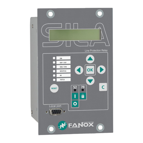
LED indicators The SILA front panel has 8 LEDs. The operation of the LED indicators can be checked from the test menu. The user can change the configuration of the LEDs depending on its requirements. www.fanox.com EN_FANOXTD_GUIDE_SIL_OCEFPrimaryDist_SILA_R002.doc 8 / 36... -
Page 9: How To Install Sicom Software
How to install SICOM software To install the SICom it is necessary the following link: http://fanox.blob.core.windows.net/sicom/publish.htm The link will open the next screen, where button “install” must be pressed: The necessary drivers depending on the operative system can be downloaded from this page. -
Page 10: Functional Diagram
3. FUNCTIONAL DIAGRAM 4. SELECTION & ORDERING CODES www.fanox.com EN_FANOXTD_GUIDE_SIL_OCEFPrimaryDist_SILA_R002.doc 10 / 36... -
Page 11: Technical Specifications
IEEE Inverse curve, IEEE very inverse curve, IEEE extremely inverse curve, Defined Time. 50/51N/G Time Delay: 0.00(*) to 300 s (step 0.01 s) Time Dial (TMS): 0.02 to 2.20 (step 0.01) Curve, activation level 110% Curve, deactivation level 100% www.fanox.com EN_FANOXTD_GUIDE_SIL_OCEFPrimaryDist_SILA_R002.doc 11 / 36... - Page 12 Safe time: 0.02 to 300 s (step 0.01 s) Locking possibilities: pulse inputs, level inputs, commands. Function Enable: Yes/No 50BF (*) Time Delay: 0.02 to 1.00 s (step 0.01 s) Open circuit breaker activation threshold: 8% In www.fanox.com EN_FANOXTD_GUIDE_SIL_OCEFPrimaryDist_SILA_R002.doc 12 / 36...
- Page 13 Function Enable: Yes/No Current tap: 15 to 100% (step 1%) 46BC (*) Time Delay: 0.02 to 300 s (step 0.01 s) Timing accuracy: ±30 ms or ±0.5% (greater of both) Function Enable: Yes/No SHB (*) www.fanox.com EN_FANOXTD_GUIDE_SIL_OCEFPrimaryDist_SILA_R002.doc 13 / 36...
- Page 14 ±2% Accuracy over a band of ±20% over the nominal current and ±4% or ±5 mA (greater of both) over the rest of the range Saturation limit: 30 times rated current LOCAL COMMUNICATION 1 Local port RS232: ModBus RTU Communications REMOTE COMMUNICATION (*) 1 remote port with the following options: www.fanox.com EN_FANOXTD_GUIDE_SIL_OCEFPrimaryDist_SILA_R002.doc 14 / 36...
- Page 15 IP-54 on pannel (*) Depending on model LPCT model→50N/G, 50/51N: calculated neutral; Standard model→50N/G, 50/51N/G: measured neutral 5.1. IEC60255-151 Curves The SIL-A relay complies with the curves shown in standard IEC 60255-151: • Inverse Curve • Very Inverse Curve •...
-
Page 16: Ieee Curves
5.2. IEEE Curves The SIL-A relay complies with the curves shown in standard IEEE: • Inverse Curve • Very Inverse Curve • Extremely Inverse Curve There is a general mathematical equation that defines the time in seconds as a function of the current: ... -
Page 17: Programable Logic Control
These inputs are translated to internal binary states which later, can be assigned to logical signal to get a specific operation. Physical outputs are the real outputs of the Device. SIL-A has 4 outputs and up to 8 configurable leds, which receive the same treatment as the physical outputs, some working on output relays and others working on led diodes. - Page 18 • Remote modbus close OUTPUTS Output 3 breaker breaker • Remote • Remote DNP3.0 close protocol close breaker breaker • General trip • General trip Output 4 • Local open breaker • Local open breaker www.fanox.com EN_FANOXTD_GUIDE_SIL_OCEFPrimaryDist_SILA_R002.doc 18 / 36...
- Page 19 Not configured 79 Enable 79 Level Not configured Block Not configured 79 Block Not configured Unblock 74TCS Not configured Continuity A (*) 74TCS Not configured Continuity Logical Not configured signal 1 Logical Not configured signal 2 www.fanox.com EN_FANOXTD_GUIDE_SIL_OCEFPrimaryDist_SILA_R002.doc 19 / 36...
-
Page 20: Flowchart
LED 1. On adaptation C all the LEDs will be activated simultaneously when entering on Test Menu. In case of the outputs, they will be activated or deactivated by pressing OK key. www.fanox.com EN_FANOXTD_GUIDE_SIL_OCEFPrimaryDist_SILA_R002.doc 20 / 36... -
Page 21: Direct Access
Press the “C” key to return to the standby mode screen. Communication parameters Hold “▼” key from standby menu to access to communication parameters menu. Press the “C” key to return to the standby mode screen. www.fanox.com EN_FANOXTD_GUIDE_SIL_OCEFPrimaryDist_SILA_R002.doc 21 / 36... -
Page 22: Menus
“OK”. Use the “▲” and “▼” keys to position the cursor over the measurement and to see its value. Press the “C” key to return to the standby mode screen. (*) Depending on model www.fanox.com EN_FANOXTD_GUIDE_SIL_OCEFPrimaryDist_SILA_R002.doc 22 / 36... - Page 23 “OK” key to access the settings that belong to this group. Use the “▲” and “▼” keys to move through different settings. information that appears underneath the setting name is its value. (*) Depending on model www.fanox.com EN_FANOXTD_GUIDE_SIL_OCEFPrimaryDist_SILA_R002.doc 23 / 36...
- Page 24 Use “▼” key to choose the wanted option (permission, curve type, time dial, tap or time delay) and press “OK” to access to its settings parameters. After inserting the password 5555 it will be possible to adjust the wanted value. www.fanox.com EN_FANOXTD_GUIDE_SIL_OCEFPrimaryDist_SILA_R002.doc 24 / 36...
- Page 25 Use “▼” key till SETTINGS menu appears. Pressing “◄” key it is accessed to GENERAL settings. Use “▼” key to overview the options and press “OK” when “CT Phase Ratio” option appears. After inserting the password 5555 it will be possible to adjust the wanted value www.fanox.com EN_FANOXTD_GUIDE_SIL_OCEFPrimaryDist_SILA_R002.doc 25 / 36...
- Page 26 Use “▼” key till SETTINGS menu appears. Pressing “◄” key it is accessed to GENERAL settings. Use “▼” key to overview the options and press “OK” when “Remote COM Address option appears. After inserting the password 5555 it will be possible to select the desired value. www.fanox.com EN_FANOXTD_GUIDE_SIL_OCEFPrimaryDist_SILA_R002.doc 26 / 36...
- Page 27 Counters give us the following information: Openings Number Acumulated Amps Reclosings Number How to set a counter To set a counter from the relay it is necessary to insert the password 5555 from the specific counter menu. www.fanox.com EN_FANOXTD_GUIDE_SIL_OCEFPrimaryDist_SILA_R002.doc 27 / 36...
- Page 28 7.3.6. Commands SIL-A relay provides up to 8 commands that can be executed from the HMI: • Open / Close breaker • 79 Block / Unblock • Local / Remote Control • Reset • Reset TI (*) (*) Depending on model...
- Page 29 To visualize the rest events use “▼” key. How to delete the fault reports To delete the fault reports from the relay it is necessary to insert the password 5555 from the fault report menu. www.fanox.com EN_FANOXTD_GUIDE_SIL_OCEFPrimaryDist_SILA_R002.doc 29 / 36...
-
Page 30: Commisioning
REAR RELAY WITHSTAND GENERATION MODE SYSTEM CONNECTION ENERGY WAVEFORM Single phase Phase- NOT APPLY P-N: Neutral Phase- P-P: = 2x Phase Three phase Phase- Balanced (120°) P-N Balanced: Neutral Unbalanced (0°) P-N Unbalanced: = 4x www.fanox.com EN_FANOXTD_GUIDE_SIL_OCEFPrimaryDist_SILA_R002.doc 30 / 36... -
Page 31: Thermal Resistance
Some examples are shown below: - Current injected => I=1 A:→ ±2% accuracy is complied. - Current injected => I=2A. As this current value is 20% higher than the nominal current (In= 1A) → 4% accuracy is complied. www.fanox.com EN_FANOXTD_GUIDE_SIL_OCEFPrimaryDist_SILA_R002.doc 31 / 36... -
Page 32: Protection Functions
• 50N/G instantaneous neutral overcurrent protection: Settings: Funciton Enable: YES. Current Tap: 1xIn. Time: 2 (sec) The following information will be checked: Pick-up at 100% of the tap Output 4 is activated LED 3 is activated www.fanox.com EN_FANOXTD_GUIDE_SIL_OCEFPrimaryDist_SILA_R002.doc 32 / 36... - Page 33 Curve: IEC Inverse. Dial (TMS): 0.5 Current Tap: 16xIn. Theoretical tripping time = 5.01seconds (Fault current 32) The following information will be checked: Pick-up at 110% of the tap Output 4 is activated LED 2 is activated www.fanox.com EN_FANOXTD_GUIDE_SIL_OCEFPrimaryDist_SILA_R002.doc 33 / 36...
- Page 34 Take into account this, time is calculated through an equation and this time depends on the injected current, so doing a ramp is possible but the theoretical tripping time will not be checked. www.fanox.com EN_FANOXTD_GUIDE_SIL_OCEFPrimaryDist_SILA_R002.doc 34 / 36...
-
Page 35: Sila Protocol
N/A 74CT OK N/A OK N/A OK N/A 46BC OK N/A Trip Block OK N/A OK Data recording (Events, fault reports) OK www.fanox.com Installation_Guide_SIAB000B0021AA_Rev. 02 35 / 36... - Page 36 Installation_Guide_SIAB000B0021AA_Rev. 02 36 / 36...
Need help?
Do you have a question about the SIL-A and is the answer not in the manual?
Questions and answers