Table of Contents
Advertisement
Quick Links
Mercury+ SA2 SoC Module
Purpose
The purpose of this document is to present the characteristics of Mercury+ SA2 SoC module to the user,
and to provide the user with a comprehensive guide to understanding and using the Mercury+ SA2 SoC
module.
Summary
This document first gives an overview of the Mercury+ SA2 SoC module followed by a detailed description
of its features and configuration options. In addition, references to other useful documents are included.
Product Information
Product
Document Information
Reference / Version / Date
Approval Information
Written by
Verified by
Approved by
User Manual
Code
ME-SA2
Reference
D-0000-408-002
Name
DIUN
GLAC
DIUN
Enclustra GmbH – Räffelstrasse 28 – CH-8045 Zürich – Switzerland
Name
Mercury+ SA2 SoC Module
Version
07
Position
Design Engineer
Design Expert
Manager, BU SP
Phone +41 43 343 39 43 – www.enclustra.com
Date
19.08.2019
Date
11.09.2015
15.09.2015
19.08.2019
Advertisement
Chapters
Table of Contents

Subscribe to Our Youtube Channel
Related Manuals for Enclustra Mercury+ SA2


Summary of Contents for Enclustra Mercury+ SA2
- Page 1 Mercury+ SA2 SoC Module User Manual Purpose The purpose of this document is to present the characteristics of Mercury+ SA2 SoC module to the user, and to provide the user with a comprehensive guide to understanding and using the Mercury+ SA2 SoC module.
- Page 2 Unauthorized duplication of this document, in whole or in part, by any means is prohibited without the prior written permission of Enclustra GmbH, Switzerland. Although Enclustra GmbH believes that the information included in this publication is correct as of the date of publication, Enclustra GmbH reserves the right to make changes at any time without notice.
-
Page 3: Table Of Contents
Enclustra Build Environment ........ - Page 4 3.12 Enclustra Module Configuration Tool ........45 I2C Communication Overview .
- Page 5 4.4.1 Memory Map ..........47 Operating Conditions Absolute Maximum Ratings .
-
Page 6: Overview
The Enclustra Build Environment [14] is available for the Mercury+ SA2 SoC module. This build system allows the user to quickly set up and run Linux on any Enclustra SoC module. It allows the user to choose the desired target, and download all the required binaries, such as bitstream and preloader. It downloads and compiles all required software, such as U-Boot, Linux, and BusyBox based root file system. -
Page 7: Electrostatic Discharge
Warning! It is possible to mount the Mercury+ SA2 SoC module the wrong way round on the base board - always check that the mounting holes on the base board are aligned with the mounting holes of the Mercury+ SA2 SoC module. -
Page 8: Accessories
Enclustra Build Environment The Enclustra Build Environment (EBE) [14] enables the user to quickly set up and run Linux on any Enclustra SoC module or system board. It allows the user to choose the desired target, and download all the required binaries, such as bitstream and preloader/bootloader. -
Page 9: Intel Tool Support
Intel Tool Support The SoC devices equipped on the Mercury+ SA2 SoC module are supported by the Quartus Prime Lite Edition (or Quartus II Web Edition, for older software versions), which is available free of charge. Please contact Intel for further information. -
Page 10: Module Description
Figure 1: Hardware Block Diagram The main component of the Mercury+ SA2 SoC module is the Intel Cyclone V SoC device. Most of its I/O pins are connected to the Mercury module connectors, making up to 252 regular user I/Os available to the user. -
Page 11: Module Configuration And Product Codes
Figure 2: Product Code Fields Please note that for the first revision modules or early access modules, the product code may not respect entirely this naming convention. Please contact Enclustra for details on this aspect. Article Numbers and Article Codes Every module is uniquely labeled, showing the article number and serial number. -
Page 12: Module Label
The correspondence between article number and article code is shown in Table 2. The article code repre- sents the product code, followed by the revision; the R suffix and number represent the revision number. The revision changes and product known issues are described in the Mercury+ SA2 SoC Module Known Issues and Changes document [6]. -
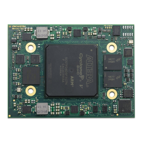
Page 13: Top And Bottom Views
Top and Bottom Views 2.4.1 Top View Figure 4: Module Top View 2.4.2 Bottom View Figure 5: Module Bottom View Please note that depending on the hardware revision and configuration, the module may look slightly dif- ferent than shown in this document. D-0000-408-002 13 / 53 Version 07, 19.08.2019... -
Page 14: Top And Bottom Assembly Drawings
Top and Bottom Assembly Drawings 2.5.1 Top Assembly Drawing Figure 6: Module Top Assembly Drawing 2.5.2 Bottom Assembly Drawing Figure 7: Module Bottom Assembly Drawing Please note that depending on the hardware revision and configuration, the module may look slightly dif- ferent than shown in this document. -
Page 15: Module Footprint
Figure 8: Module Footprint - Top View Warning! It is possible to mount the Mercury+ SA2 SoC module the wrong way round on the base board - always check that the mounting holes on the base board are aligned with the mounting holes of the Mercury+ SA2 SoC module. -
Page 16: Module Connector
Symbol Value Size 54 mm Component height top 5.0 mm Component height bottom 1.45 mm Weight 29 g Table 3: Mechanical Data Module Connector Three Hirose FX10 168-pin 0.5 mm pitch headers with a total of 504 pins have to be integrated on the base board. -
Page 17: User I/O
User I/O 2.9.1 Pinout Information on the Mercury+ SA2 SoC module pinout can be found in the Enclustra Mercury Master Pinout [11], and in the additional document Enclustra Module Pin Connection Guidelines [10]. Warning! Please note that the pin types on the schematics symbol of the module connector and in the Master Pinout document are for reference only. -
Page 18: I/O Pin Exceptions
The I/O pin exceptions are pins with special functions or restrictions (for example, when used in combination with certain Mercury boards they may have a specific role). Table 6 lists the I/O pin exceptions on the Mercury+ SA2 SoC module. D-0000-408-002 18 / 53 Version 07, 19.08.2019... -
Page 19: Differential I/Os
Table 6: I/O Pin Exceptions When the Mercury+ SA2 SoC module is used in combination with a Mercury+ PE1 base board as a PCIe device, the PERST# signal coming from the PCIe edge connector on the module connector pin A-104 (HPS_GPIO59_MISO) is driven further to IO_B5A_RX_R6_PERST#_W22_N. - Page 20 Bank Connectivity VCC_IO VREF MGT Bank L0 Module connector 1.1 V MGT Bank L1 Module connector 1.1 V MGT Bank L2 Module connector 1.1 V User selectable Bank 3A Configuration, Fast Ethernet PHYs VCC_CFG_HPS_B3A User selectable Bank 3B Module connector VCC_IO_B3B_B4A VCC_IO_B3B_B4A User selectable...
-
Page 21: Vcc_Io Usage
Table 8: VCC_IO Pins If the Mercury+ SA2 SoC module is used in combination with a base board having only two module connec- tors, the VCC_IO_B3B_B4A pin that powers I/O banks 3B and 4A is connected to the on-board generated 1.8 V supply voltage. -
Page 22: Signal Terminations
2.9.7 HPS I/O Pins Table 9 gives an overview over the HPS pin connections on the Mercury+ SA2 SoC module. Only the pins marked with “user functionality” are available on the module connector. The suggested functions below are for reference only - always verify your HPS pinout with the Intel device handbook. -
Page 23: Multi-Gigabit Transceiver (Mgt)
HPS_GPIO Function Connection 36, 38-39, 45-47 SD card/eMMC /user functionality Module connector/eMMC flash Gigabit Ethernet interrupt (input, active-low) Gigabit Ethernet PHY Boot mode 0 BOOT_MODE0 Gigabit Ethernet link status (ETH_LED2#, input, Gigabit Ethernet PHY active-low) Boot mode 1/eMMC enable signal (output, BOOT_MODE1_EMMC_EN# active-low) Power good (input, active-high) -
Page 24: Power
Power Generation Overview The Mercury+ SA2 SoC module uses a 5 - 15 V DC power input for generating the on-board supply voltages (1.1 V, 1.2 V, 1.35 V, 1.55 V, 1.8 V, 2.5 V, 3.3 V and 5.0 V). Some of these voltages (1.8 V, 2.5 V, 3.3 V) are accessible on the module connector. -
Page 25: Power Enable/Power Good
DC/DC converters for 1.1 V, 1.2 V, 1.5 V, 1.8 V, and 2.5 V. The 3.3 V supply is always active. The PWR_EN input is pulled to VCC_3V3 on the Mercury+ SA2 SoC module with a 10 k resistor. The PWR_GOOD signal is pulled to VCC_3V3 on the Mercury+ SA2 SoC module with a 10 k resistor. -
Page 26: Voltage Supply Outputs
SoC is adequately cooled. Table 14 lists the heat sink and thermal pad part numbers that are compatible with the Mercury+ SA2 SoC module. Details on these parts and additional information that may assist in selecting a suitable heat sink for the Mercury+ SA2 SoC module can be found in the Enclustra Modules Heat Sink Application Note [17]. -
Page 27: Voltage Monitoring
Clock Generation A 50 MHz oscillator is used for the Mercury+ SA2 SoC module clock generation. The 50 MHz clock is fed to the HPS. A clock divider generates a 25 MHz clock for Ethernet and the second HPS clock. -
Page 28: Reset
LEDs Three LEDs on the Mercury+ SA2 SoC module are connected to the FPGA logic and the HPS in parallel; it is recommended to drive the FPGA pins to a high impedance state before driving the HPS pins and vice versa. -
Page 29: Ddr3L Sdram Type
Please check the user manual regularly for updates. Any parts with different speed bins or temperature ranges that fulfill the requirements for the module variant may be used. 2.15.2 Signal Description Please refer to the Mercury+ SA2 SoC Module FPGA Pinout Excel Sheet [4] for detailed information on the DDR3L SDRAM connections. 2.15.3 Termination Warning! No external termination is implemented for the data signals on the Mercury+ SA2 SoC module. -
Page 30: Qspi Flash
Parameter Value SDRAM protocol DDR3 PHY settings - supply voltage 1.35 V DDR3L Memory device speed grade 400 MHz Total interface width 32 bit Row bits Column bits Bank bits tRAS 37.5 ns tRCD 15 ns 15 ns tREFI 7.8 us tRFC 260.0 ns 15.0 ns... -
Page 31: Qspi Flash Type
512 Mbit Cypress (Spansion) Table 22: QSPI Flash Type Warning! Other flash memory devices may be equipped in future revisions of the Mercury+ SA2 SoC module. Please check the user manual regularly for updates. 2.16.2 Signal Description The QSPI flash is connected to the HPS pins 29-34 and to the FPGA SPI configuration port. Some of the signals are available on the module connector, allowing the user to program the QSPI flash from an external master. -
Page 32: Signal Description
16 GB Kingston Table 24: eMMC Flash Type Warning! Other flash memory devices may be equipped in future revisions of the Mercury+ SA2 SoC module. Please check the user manual regularly for updates. 2.18.2 Signal Description The eMMC flash signals are connected to the HPS pins 36, 38-39, 45-47. The data and command pins are shared between eMMC and SD card interfaces. -
Page 33: Gigabit Ethernet
Please note that the RGMII delays in the Ethernet PHY need to be configured before the Ethernet interface can be used. This is done in the patch for the Preloader (SPL) provided in the Mercury+ SA2 SoC module reference design [2]. -
Page 34: Dual Fast Ethernet
Fast Ethernet PHYs have a shared MDIO interface and a shared interrupt line. Details on connections are available in the Mercury+ SA2 SoC Module User Schematics [5] and in the FPGA Pinout Excel Sheet [4]. The 25 MHz clock for the Fast Ethernet must be supplied via FPGA pin AD11. -
Page 35: External Connectivity
2.21 Cypress FX3 USB 3.0 Controller The Mercury+ SA2 SoC module features a USB 3.0 controller from Cypress, which allows data transfers to a host computer using speeds of over 300 MB/s. The USB controller is connected to the FPGA module using a slave FIFO interface that can be configured for 16-bit or 32-bit mode using an interface clock of 100 MHz. -
Page 36: Cypress Fx3 Pinout
2.22 USB 2.0 The Mercury+ SA2 SoC module has an on-board USB 2.0 PHY connected to the SoC device. The USB inter- face can be configured for USB host or for USB device. Please note that simultaneous usage of the USB 3.0 device interface (FX3) and USB 2.0 in device mode is not USB compliant;... -
Page 37: Usb Phy Type
A real-time clock is connected to the I2C bus. The RTC features a battery-buffered 128 bytes user SRAM and a temperature sensor. See Section 4 for details on the I2C bus on the Mercury+ SA2 SoC module. VBAT pin of the RTC is connected to VCC_BAT on the module connector, and can be connected directly to a 3 V battery. - Page 38 Manufacturer ATSHA204A-MAHDA-T (default) Atmel DS28CN01 (assembly option) Maxim Table 32: EEPROM Type An example demonstrating how to read data from the EEPROM is included in the Mercury+ SA2 SoC module reference design [2]. D-0000-408-002 38 / 53 Version 07, 19.08.2019...
-
Page 39: Device Configuration
(PS) implementation, and not for active serial configuration (AS). The ASDATA0_ASDO connection in revision 1 was correct for AS, but incorrect for PS, however both configuration modes were unsupported or untested on Enclustra side. Connections to ASDATA1-3 were removed on revision 2. It is planned that revision 2 modules implement passive serial configuration from the Cypress FX3 device. -
Page 40: Module Connector C Detection
All configuration signals except for BOOT_MODE must be high impedance as soon as the device is released from reset. Violating this rule may damage the equipped SoC device, as well as other devices on the Mercury+ SA2 SoC module. HPS and FPGA Configuration Pins The BSEL and CSEL pins determine in which memory interface is the boot loader stored and how to clock the interface;... -
Page 41: Jtag
HPS 00010 Table 34: Boot Modes Please note that the passive serial mode is not supported on the Mercury+ SA2 SoC module nor has it been tested on Enclustra side. JTAG The FPGA and the HPS JTAG interfaces are connected into one single chain available on the module con- nector. -
Page 42: Jtag On Module Connector
range. When the VCC_CFG_HPS_B3A is set to 1.8 V, the JTAG interface is functional only if the JTAG clock frequency is lowered. This is an intermittent timing issue that affects revision 1 modules and which is planned to be fixed in future revisions. By default, the JTAG clock frequency is set to 24 MHz;... -
Page 43: External Connectivity
The VCC pin of the programmer must be connected to VCC_CFG_HPS_B3A. It is recommended to add 22 series termination resistors between the module and the JTAG header, close to the source. Please refer to the Enclustra Module Pin Connection Guidelines for details on JTAG interface. D-0000-408-002 43 / 53... -
Page 44: Passive Serial Configuration
Passive Serial Configuration In the passive serial configuration mode the FPGA bitstream is programmed from an external source into the SPI port of the FPGA. The HPS is configured afterwards via HPS2FPGA bridge. For more information, please refer to the Cyclone V datasheet [18]. eMMC Boot Mode In the eMMC boot mode, the HPS boots from the eMMC flash located on the module and configures the FPGA logic from the HPS. -
Page 45: Enclustra Module Configuration Tool
SoC device, as well as other devices on the Mercury+ SA2 SoC module. 3.12 Enclustra Module Configuration Tool The QSPI flash on the Mercury+ SA2 SoC module can be programmed via Cypress FX3 using the Enclustra Module Configuration Tool (MCT) [16]. D-0000-408-002 45 / 53 Version 07, 19.08.2019... -
Page 46: I2C Communication
4 I2C Communication Overview The I2C bus on the Mercury+ SA2 SoC module is connected to the SoC device, EEPROM, RTC and FX3 USB 3.0 controller, and is available on the module connector. This allows external devices to read the module type and to connect more devices to the I2C bus. -
Page 47: Secure Eeprom
An example demonstrating how to read the module information from the EEPROM memory is included in the Mercury+ SA2 SoC module reference design. Warning! The secure EEPROM is for Enclustra use only. Any attempt to write data to the secure EEPROM causes the warranty to be rendered void. 4.4.1... -
Page 48: Product Information
Module Product Family Reserved Revision Product Information Mercury+ SA2 SoC module 0x032A 0x[XX] 0x[YY] 0x032A [XX][YY] Table 39: Product Information Module Configuration Addr. Bits Comment Min. Value Max. Value Comment SoC Type See SoC type table (Table 41) 0x08 SoC device speed grade... -
Page 49: Operating Conditions
5 Operating Conditions Absolute Maximum Ratings Table 42 indicates the absolute maximum ratings for Mercury+ SA2 SoC module. The values given are for reference only; for details please refer to the Cyclone V Datasheet [18]. Symbol Description Rating Unit VCC_MOD Supply voltage relative to GND -0.5 to 16... -
Page 50: Ordering And Support
6 Ordering and Support Ordering Please use the Enclustra online request/order form for ordering or requesting information: http://www.enclustra.com/en/order/ Support Please follow the instructions on the Enclustra online support site: http://www.enclustra.com/en/support/ D-0000-408-002 50 / 53 Version 07, 19.08.2019... - Page 51 List of Figures Hardware Block Diagram ........10 Product Code Fields .
- Page 52 I2C Addresses ..........47 EEPROM Sector 0 Memory Map .
- Page 53 [1] Enclustra General Business Conditions http://www.enclustra.com/en/products/gbc/ [2] Mercury+ SA2 SoC Module Reference Design Ask Enclustra for details [3] Mercury+ SA2 SoC Module IO Net Length Excel Sheet Ask Enclustra for details [4] Mercury+ SA2 SoC Module FPGA Pinout Excel Sheet Ask Enclustra for details...
Need help?
Do you have a question about the Mercury+ SA2 and is the answer not in the manual?
Questions and answers