Advertisement
Quick Links
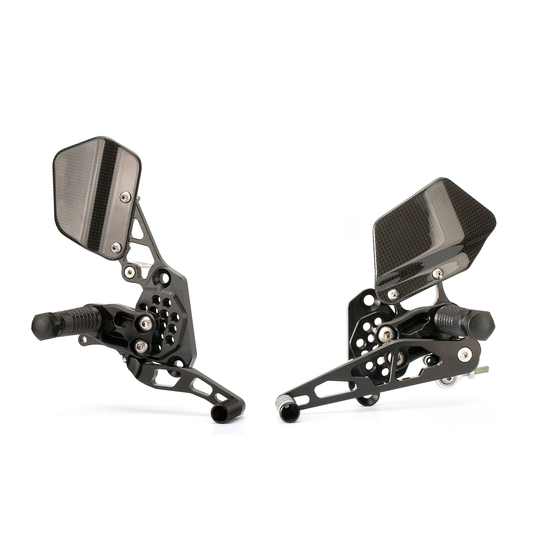
Original Fußrastenanlage abschrauben
und Kabel des Bremslichthalters durch
die Schwinge verlegen (A).
Dismantle the original foot rest system
and lay the cable of the brake light
holder through the swing arm (A).
C
D
Es ist unbedingt darauf zu achten, dass alle Teile der Fußrastenanlage ein Mindestabstand von 5 mm zu
anderen Fahrzeugteilen haben.
Be cautious that all parts of the footrest sytem have at least 5mm distance from parts of the motorbike.
AS 31 GT
H03P- installation manual
A
Bremslichtfeder
einhängen.
Install spring for
brakelight.
Adapter (C) auf den
Bremszylinder
schrauben, Brems-
hebellhöhe einstellen
und Bolzen (D) von
Rückseite einführen
und mit Scheibe und
Splint sichern.
Screw on the adapter
(C) on the brake
cylinder, adjust the
height of the brake
lever. Insert the
adapter pin (D) from
the back and fix it with
the collar and the split
pin.
F:\Produkte\1_AS 31 GT\32Honda\H03P
AS 31 GT mit Schrauben und Scheibe
8mm montieren (B). Anzugsmoment
25Nm.
To mount with srew M8 and collar
8mm(B).
Tightening torque 25Nm.
Normalschaltung
normal shifting
Umkehrschaltung
inverse shifting
Scheibe / collar 12-6-9
Stand
01/02
REV
00/00
B
Advertisement

Related Manuals for gilles.tooling AS 31 GT


Summary of Contents for gilles.tooling AS 31 GT
- Page 1 (A). Adapter (C) auf den Bremszylinder schrauben, Brems- hebellhöhe einstellen AS 31 GT mit Schrauben und Scheibe und Bolzen (D) von 8mm montieren (B). Anzugsmoment Rückseite einführen 25Nm. und mit Scheibe und Splint sichern.
- Page 2 Modell Baujahr CBR 900 RR SC 44 ´00 -´01 Honda Produkt- CBR 900 RR SC 50 ´02- manage- Art.No: H03-* ment (* = Farbe, harteloxiert: G (gold) ; T (titan) or B (schwarz) Serienposition - 9 Einstellmöglichkeiten (siehe rechts) - Fersenschützer beidseitig - grenzenlose Bodenfreiheit (bei der H03 P-* mit der Racing-Version) 14 (15) (16) 17...
Need help?
Do you have a question about the AS 31 GT and is the answer not in the manual?
Questions and answers