Table of Contents
Advertisement
Quick Links
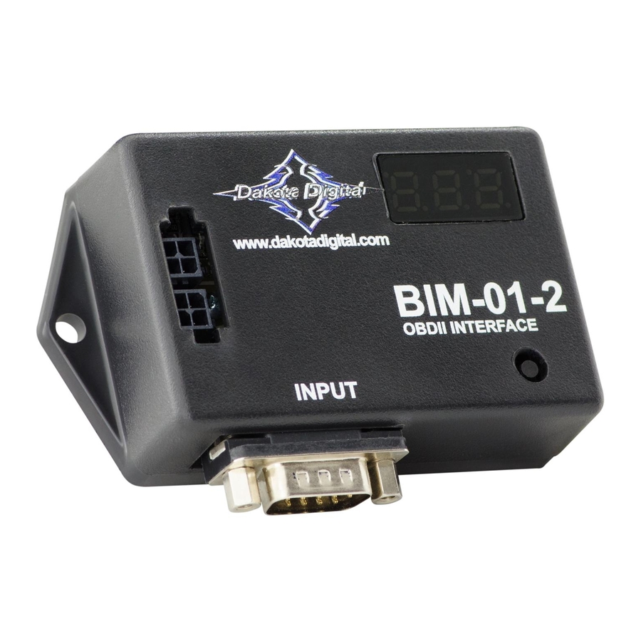
Bus Interface Module for OBD-II vehicle interface
BIM-xx-2 power & data connectors.
Either one can be used.
www.dakotadigital.com
techsupport@dakotadigital.com
605-332-6513
INPUT
Connect to the BIM-01-2.
This Bus Interface Module has an input to read engine information from vehicles using the GM 1996-up OBD-II protocol,
Ford 1996-up OBD-II protocol, some Chrysler 2000-up OBD-II protocol, or CAN (SAE J1979) OBD-II protocol. CAN SAE
J1979 OBD-II is used on all vehicles 2008 and newer and some vehicles from 2004 – 2008. There are two interface (I/O)
ports on the module. Either one can be connected to the gauge system or to another module, allowing several units to be
daisy chained together. Do not connect the I/O port to anything other than a Dakota Digital control box or BIM. Do not
mount the module in the engine compartment; it should be mounted in interior of the vehicle.
The BIM-01-2 does not use one of the 16 available bus ID's like other Dakota Digital BIM units do. Speed and RPM data
are transmitted and updated every 0.1 second. The remaining data is sent one at a time in sequence along with the
speed and RPM. As an example on the first update speed, RPM, and engine temp would be sent. On the next update
speed, RPM, and intake temp would be sent. This will continue with the other data that is available and then will start
over again with speed, RPM, and engine temp.
The engine and transmission information that is available from the unit depends on the year, make, model, and options of
the vehicle. Some of the possible values are: engine RPM, vehicle speed, engine coolant temperature, intake air
temperature, transmission fluid temperature, transmission gear position, vacuum/boost and ambient air temperature.
Data that should always be available: RPM, speed, engine temp, intake temp, engine indicator(MIL)
Data that is transmission dependent: Transmission temp, transmission gear position
Data that is body control/ECM dependent: ambient air temp, engine oil pressure, fuel level, vacuum/boost
BIM-01-2
OBDII INTERFACE
setup/status switch
BIM-xx-2 18 inch power/data harness
BIM-01-2
Connect to vehicle
diagnostic port
OBD-II
Connect directly to
another BIM-xx-2 or control box
MAN #650500F
Advertisement
Table of Contents

Related Manuals for Dakota Digital BIM-01-2


Summary of Contents for Dakota Digital BIM-01-2
- Page 1 The BIM-01-2 does not use one of the 16 available bus ID’s like other Dakota Digital BIM units do. Speed and RPM data are transmitted and updated every 0.1 second. The remaining data is sent one at a time in sequence along with the speed and RPM.
- Page 2 This will not turn on the indicator for a lamp test function when the key is on, but the engine is not running. This indicator can be enabled or disabled in the BIM-01-2 setup. Some gauge features require a minimum...
- Page 3 Press and release SW1 until SENDER BUS F or SENDER BUS C is displayed depending on your unit choice. • Press and hold SW1 until DONE is displayed. Using oil pressure from the BIM-01-2 (if available) • Hold the SW1 switch from the instrument system control box while turning the key on. The message display should show SETUP.
- Page 4 Press and release either switch until INPUT is displayed. Press and hold either switch to enter INPUT menu. • Press and release either switch until BIM is displayed. Press and hold either switch to select BIM. Using oil pressure from the BIM-01-2 (if available) • With ignition on. Press and hold both switches to enter SETUP.
- Page 5 BIM setup: Enable or disable engine indicator status from the BIM-01-2 • Hold the switch on the BIM-01-2 case while turning the key on. The BIM display will show the current revision code while this is held. • Release the switch.
- Page 6 61 and 62 are gauge ID’s and F1 and F2 are scan tool ID’s. To set or change the diagnostic bus ID numbers: • Hold the switch on the BIM-01-2 case while turning the key on. The BIM display will show the current revision code while this is held. •...
- Page 7 Send no money. We will bill you after repair. Dakota Digital Limited Lifetime Warranty DAKOTA DIGITAL warrants to the ORIGINAL PURCHASER of this product that should it, under normal use and condition, be proven defective in material or workmanship for the lifetime of the original vehicle it was installed in, such defect(s) will be repaired or replaced at Dakota Digital’s option.
Need help?
Do you have a question about the BIM-01-2 and is the answer not in the manual?
Questions and answers