Advertisement
Quick Links
This manual covers the aspects of installation, operation, and troubleshooting of the
The CRC-2000 was designed to work with CAN bus GM LS engine/drivetrain packages, as either a complete transplant
from a stock vehicle, or a Connect Cruise, using a GM ECU programmed with US SAE code.
•
Works with 2008 and newer GM CAN bus engine/drivetrain packages with US SAE code.
•
Requires a 4,000 Pulse Per Mile VSS square wave speed signal.
o
GM ECU Speed output or VSS Out, (not VSS High).
o
Dakota Digital SPD OUT from a control box.
•
Mix and match engines, transmissions and ECUs will most likely NOT work.
•
Advanced tuning to the ECU could disable the cruise control operation.
•
The CRC-2000 is designed to only work with a GM CAN bus computer system.
o
Not designed for Ford, Mopar, or aftermarket EFI systems like Holley
CRC-2000 "Drive-by-Wire" cruise control.
Table of Contents
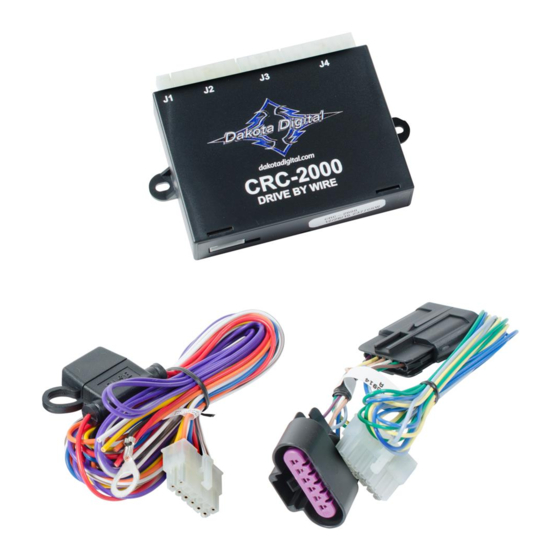
Parts List
Connectors and Pin Outs
Wiring / J2 Main Harness
Wiring / J2 Optional Resistor Wiring
Wiring / J2 Clutch Switches
Wiring / J2 Brake and LED Relay
Wiring / J3 Cruise Handles
Wiring / J4 Throttle connections
Trouble Shooting
Operations
Safety Procedures
Service / Warranty
CRC-2000
Drive-by-Wire Cruise Control System
Page 2
Page 3
Page 4
Page 6
Page 6
Page 7
Page 9
Page 10
Page 12
Page 13
Page 14
Page 16
[1]
MAN #650553:A
Advertisement

Related Manuals for Dakota Digital CRC-2000


Summary of Contents for Dakota Digital CRC-2000
- Page 1 This manual covers the aspects of installation, operation, and troubleshooting of the CRC-2000 “Drive-by-Wire” cruise control. The CRC-2000 was designed to work with CAN bus GM LS engine/drivetrain packages, as either a complete transplant from a stock vehicle, or a Connect Cruise, using a GM ECU programmed with US SAE code.
- Page 2 Pedals vary in build and operation. The pin layout must be a single row as shown in the purple pedal plug of the 250-2766 below. If the pins are turned, or the pedal has a dual row of pins, the CRC-2000 will not function, and the wiring and cannot be modified “to make work”.
- Page 3 CONNECTORS AND PIN OUTS The CRC-2000 has four connectors on the front that we use. They are labeled as: • J1 – Not Used • J2 – Power/Ground/Input harness • J3 – Handle/Switch harness • J4 – Pedal harness The small connector in the back is not used, but there is a small cutaway for an LED, that can used to observe operation and limited diagnostics, (see page [12]).
- Page 4 STEP BY STEP CONNECTIONS Connecting Main Harness [J2] Wire colors Ground Output to activate “cruise” indicator on Dakota Digital dash or ground side of LED Orange Yellow Clutch Switch triggered by a positive voltage White Clutch Switch triggered by a ground signal Speed input wire –...
- Page 5 This can be determined to exist by testing the output wire or terminal for DC voltage. Many ECUs have a 5-volt reference voltage with key the on. Dakota Digital control boxes do not have a pull up voltage, and the enclosed resistor will need to be added. Basic Diagram All Dakota Digital control boxes, (and the GPS-50-2 CRUISE terminal), will need the pull up resistor added, as long as the control box is being fed a speed signal into the speed input wires.
- Page 6 Special Wiring Notes Cruise Indicator (Orange): The orange wire produces a negative trigger to operate the cruise indicator on a Dakota Digital VFD3, VHX, HDX or RTX dash system. The orange wire will connect to “CRUSE” on these control boxes.
- Page 7 Cold Side Brake Wiring (with and without LED tail lights) MAN #650553:A...
- Page 8 When pinning the plug of the handle, match the colors of the handle to the letters on the plastic plug. The Dakota Digital HND-1 and HND-3 can only be used with the 394207 harness. The colors of the 394207 may vary, and these are the known variants we have seen.
- Page 9 Handle Wire Harnesses [J3] 394206 with HND-2 The HND-2 colors will match the colors of the 394206 harness. BROWN GREEN The HND-2 cannot be used with YELLOW the 394207 harness. On occasion, a GM stock turn signal lever with cruise can be used with the 394206.
- Page 10 Throttle Pedal Harness [J4] The throttle pedal harness is also a plug and play style, only for a GM pedal, and only for one style. The pins must be side by side; not front to back, nor a dual row of pins. The harness cannot be rewired for different pedals as they may operate on different voltages.
- Page 11 A, C, D, and F can be ground or power, as our throttle harness merely acts as a pass through. When looking for a ground reference to ground the CRC-2000 to, one needs to verify the correct wire. 2008-2013 Silverados and Sierras – Color Pattern of 250-2766 throttle harness...
- Page 12 TROUBLE SHOOTING Pedal Voltage Tests The pedal voltages have to be within a certain tolerance for the cruise to operate. Testing J4 pins will require a volt meter for accurate voltages, a test light will not work. Key on only, with pedal harness fully connected, measure the following pins on J4 (see page 10). Color at J4 Pedal at Rest Pedal Wide Open...
- Page 13 MPH of your set speed, then press and release the RESUME/ACCEL button. About Dakota Digital Cruise Control The performance of the Cruise Control is dependent upon the condition of the engine, its size and even by the type of emission control equipment it has.
- Page 14 DO NOT INSTALL THIS SYSTEM ON A DIESEL-POWERED VEHICLE WHICH HAS A MANUAL TRANSMISSION WITHOUT A DISENGAGEMENT SWITCH ON THE CLUTCH PEDAL ASSEMBLY. (Contact Dakota Digital Sales to purchase part: SEN-4206) WARNING Failure to follow the instruction manual could not only cause the system to work improperly, but could cause the vehicle to go into ‘limp-mode’, possibly causing damage to your vehicle and injury and/or death to you and your passengers.
- Page 15 PAGE INTENTIONALLY LEFT BLANK [15] MAN #650553:A...
- Page 16 Dakota Digital 36 Month Warranty DAKOTA DIGITAL warrants to the ORIGINAL PURCHASER of this product that should it, under normal use and condition, be proven defective in material or workmanship for 36 MONTHS FROM THE DATE OF PURCHASE, such defect(s) will be repaired or replaced at Dakota Digital’s option.
Need help?
Do you have a question about the CRC-2000 and is the answer not in the manual?
Questions and answers