Advertisement
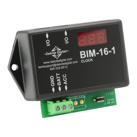
BIM-16-1
Clock Bus Interface Module
To gauge control box
or another BIM
BIM-16-1
www.dakotadigital.com
techsupport@dakotadigital.com
CLOCK
605-332-6513
setup/status switch
Connect to main
chassis ground
+12V
KEY ON POWER
+12V
CONSTANT BATTERY POWER
(fused 5 - 20 AMP max)
(fused 5 - 20 AMP max)
This Bus Interface Module has a constant battery power input and an accessory input. The battery power keeps the
clock running and the accessory input powers the bus interface port. There are two interface (I/O) ports on the
module. Either one can be connected to the gauge system or to another module, allowing several units to be daisy
chained together. Do not connect the I/O port to anything other than a Dakota Digital gauge or BIM. Do not mount the
module in the engine compartment; it should be mounted in interior of the vehicle.
Each BIM needs a unique ID number assigned to it. It can be assigned an ID from 1 – 16, or turned off. The factory
default ID number is 7. The clock can run in 12 hour or 24 hour format. The factory default time format is 12 hour.
MAN #650344:B
Advertisement
Table of Contents

Related Manuals for Dakota Digital BIM-16-1


Summary of Contents for Dakota Digital BIM-16-1
- Page 1 Either one can be connected to the gauge system or to another module, allowing several units to be daisy chained together. Do not connect the I/O port to anything other than a Dakota Digital gauge or BIM. Do not mount the module in the engine compartment;...
- Page 2 To set or change the ID numbers and the time format: Hold the switch beside the BIM terminal strip while turning the key on. The BIM display will show the current revision code while this is held. Release the switch. The display will show “”. ...
- Page 3 Troubleshooting quick tips: While the BIM is operating, the dot in the upper left corner of the display will indicate the status. On steady indicates the accessory power is on but not receiving any bus activity. Flashing slowly indicates it is communicating on the bus. If the switch is pressed while the accessory power is off the dot will flash rapidly until the switch is released.
- Page 4 Dakota Digital’s option. This warranty does not cover nor extend to damage to the vehicle’s systems, and does not cover diagnosis, removal or reinstallation of the product.
Need help?
Do you have a question about the BIM-16-1 and is the answer not in the manual?
Questions and answers