Advertisement
Quick Links
The easiest system to install and use on the market.
The Dakota Digital universal gear shift sender consists of three main components; the sensor,
decoder, and mounting brackets. The sensor mounts to the transmission and converts the transmission
linkage arm position into an electrical signal. The decoder converts the electric signal from the sensor into
the individual outputs for each gear and provides the neutral safety and backup features. The outputs are
selectable for positive or negative outputs. This unit can also support single-wire indicators from Dakota
Digital, Inc. The mounting brackets attach the sensor to the transmission housing and linkage arm.
The only parts of the gear shift sender that are different for the different transmissions are the
mounting brackets. The GM 350, 400, and 700-R4 use the same linkage connector and mounting plate,
but different holes in the mounting plate. The Ford C-6 and C-4 each have different mounting plates and
linkage connectors. For other transmissions, a universal mounting plate is provided.
To back-up lights (optional)
fused +12V with key in 'ON'
To ECM Park-Neutral input (optional)
To neutral safety relay (optional)
INDIVIDUAL
BULBS
STR
SYSTEM
DGS-1
DGS-2
VFD/VHX
SYSTEM
ODYR/SLX
GAUGE
DGS-3
DGS-4
LOKAR
(- OUT)
Universal Gear Shift Sender
and 'START' positions
to Chassis Ground
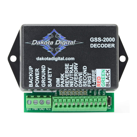
DIM
PARK
REVERSE NEUTRAL
RED
RED
PARKING
WIRE (+)
WIRE (+)
LIGHTS
NOT
PARK
REVERSE
USED
TERMINAL
TERMINAL
GREEN
GRAY
PARKING
WIRE (+)
WIRE (+)
LIGHTS
GREEN
GRAY
NOT
WIRE (+)
WIRE (+)
USED
NOT
NOT
NOT
USED
USED
USED
NOT
NOT
NOT
USED
USED
USED
NOT
NOT
NOT
USED
USED
USED
PURPLE
YELLOW
PARKING
WIRE (-)
WIRE (-)
LIGHTS
GSS-2000
Dakota Digital
GSS-2000 DECODER
B.U. PWR GND N.S.
SW
OVRDRV
DRIVE
RED
RED
RED
WIRE (+)
WIRE (+)
WIRE (+)
NEUTRAL
OVRDRV
DRIVE
TERMINAL
TERMINAL
TERMINAL
PURPLE
YELLOW
ORANGE
WIRE (+)
WIRE (+)
WIRE (+)
PURPLE
YELLOW
ORANGE
WIRE (+)
WIRE (+)
WIRE (+)
NOT
NOT
NOT
USED
USED
USED
NOT
NOT
NOT
USED
USED
USED
NOT
NOT
NOT
USED
USED
USED
BLUE
BROWN or
ORANGE
WIRE (-)
NOT USED
or BROWN
1
Programming LEDs
Programming Switch
to sensor BLACK wire
to sensor GREEN wire
to sensor RED wire
SECOND
FIRST
1-WIRE
RED
RED
NOT
WIRE (+)
WIRE (+)
USED
SECOND
FIRST
NOT
TERMINAL
TERMINAL
USED
BLUE
BROWN
NOT
WIRE (+)
WIRE (+)
USED
BLUE
BROWN
NOT
WIRE (+)
WIRE (+)
USED
NOT
NOT
GEAR
USED
USED
TERMINAL
NOT
NOT
White/Green
USED
USED
WIRE
NOT
NOT
YELLOW
USED
USED
WIRE
WHITE or
GREEN or
NOT
ORANGE
WHITE
USED
MAN# 650023B
Advertisement

Related Manuals for Dakota Digital GSS-2000


Summary of Contents for Dakota Digital GSS-2000
- Page 1 GSS-2000 The easiest system to install and use on the market. The Dakota Digital universal gear shift sender consists of three main components; the sensor, decoder, and mounting brackets. The sensor mounts to the transmission and converts the transmission linkage arm position into an electrical signal. The decoder converts the electric signal from the sensor into the individual outputs for each gear and provides the neutral safety and backup features.
-
Page 2: Parts List
CONNECTING TO THE GEAR SHIFT DISPLAY Gear shift displays are not included with the GSS-2000, but it will interface with all of the standard display systems available. Each gear output will provide 12 volts at up to 0.3 amperes or can be programmed to provide grounding outputs. - Page 3 1. Place the transmission in PARK and make sure the key is off. 2. Press and hold the set switch on the GSS-2000 decoder while turning the key on. 3. The lights should come on either all green or all red. RED is for +12V outputs for Dakota Digital and most other displays.
- Page 4 To Ignition Switch Starter Wire GREEN Cut wire between starter solenoid and the wire that feeds it from the ignition switch To POWER terminal on GSS-2000 Decoder BLUE do not connect (there will be two wires in one terminal at decoder)
- Page 5 If a Kugel adjustable shifter is being used, you will need a Kugel nut to attach the sensor to the shift linkage. The Kugel nut is available from Dakota Digital, Inc. As the transmission is shifted through all of the gears, the sensor arm should not hit either of its stops, or get ‘bound’...
- Page 6 Mounting to a GM 350, 400, or 700-R4 transmission. MAN# 650023B...
- Page 7 Mounting to a Ford C-6 transmission Depending on the shifter you are using, you may use the linkage connector provided. The bottom hole is for the sensor rod, the center hole is a pivot point for the connector, and the upper hole connects to the linkage rod.
- Page 8 The GM, Ford C-6, and universal mounting plates secure to the transmission oil pan using the supplied 1” bolt, spacer, and washer provided in the kit. On the universal mounting plate, the holes will have to be drilled to line up with the pan bolts being used on the transmission. transmission oil pan Use 3/8"...
- Page 9 Mounting to a Ford C-4 transmission This mounting plate connects to the lower two bolts of the four bolt plate located on the left side of the transmission just behind the shift linkage arm. Ford C-4 linkage connector. Depending on the shifter you are using, you may use the linkage connector provided. The bottom hole is for the sensor rod, the center hole is a pivot point for the connector, and the upper hole connects to the linkage rod.
-
Page 10: Troubleshooting Guide
This Warranty is in lieu of all other expressed warranties or liabilities. Any implied warranties, including any implied warranty of merchantability, shall be limited to the duration of this written warranty. No person or representative is authorized to assume, for Dakota Digital, any liability other than expressed herein in connection with the sale of this product.
Need help?
Do you have a question about the GSS-2000 and is the answer not in the manual?
Questions and answers