Table of Contents
Advertisement
Quick Links
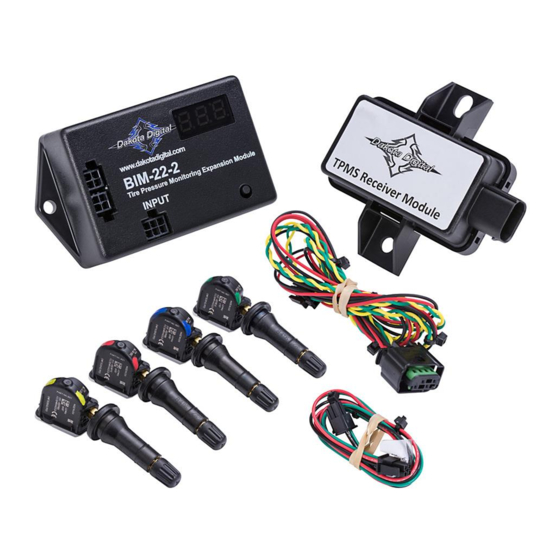
BIM-22-2
Bus Interface Module for TPMS
(Tire Pressure Monitoring System)
This Bus Interface Module (BIM) communicates with a TPMS Receiver Module which receives tire pressures and other
information from four TPMS sensors installed in a vehicle's tires. There are three interface (I/O) ports on the module.
Two of these can be connected to a Dakota Digital instrument system or to another BIM, allowing several units to be
daisy chained together. Do not connect these I/O ports to anything other than a Dakota Digital control box or BIM.
Ensure all BIM units are connected properly. On appropriate VHX, VFD3, and VFD3X systems, use the BIM-XX-1
harness (not shown). On HDX and other VHX, VFD3, and VFD3X systems, use the BIM-XX-2 harness. The interface
labeled "INPUT" on the BIM-22-2 is connected to the TPMS Receiver Module using the TPMS Receiver Module
adapter harness.
The TPMS sensors transmit pressures and other information wirelessly through an RF signal. They are to be mounted
inside the vehicle's tires; replacing normal valve stems. We recommend that the tires be rebalanced after TPMS
sensors are installed. Do not mount the BIM-22-2 and TPMS Receiver Module in the engine compartment; they
should be mounted in the interior of the vehicle. The BIM-22-2 should be installed in a location where its display and
switch are accessible in the event a new TPMS sensor needs to be installed in the system (see BIM Learn Sensors
Mode). In situations where TPMS reception is not adequate inside the interior of the vehicle, the weatherproof TPMS
Receiver Module can be mounted outside on the chassis near the center of the vehicle for better reception of the RF
transmission signals from the TPMS sensors.
The BIM-22-2 system provides tire pressures in PSI (pounds per square inch) for each of the vehicle's four tires to a
control box. When the vehicle is first turned on, dashes will be displayed on the gauge until the sensors have activated
or "woken up" from their sleeping state. The sensors wake up by driving the vehicle or if a pressure change of at least
2 PSI has taken place. This behavior of going to sleep when the vehicle is not moving vastly prolongs a sensor's
battery life. After the sensors wake up, they report pressures to the TPMS Receiver Module, which in turn are reported
through the BIM-22-2 to the control box.
MAN#650598
Advertisement
Table of Contents
Troubleshooting

Related Manuals for Dakota Digital BIM-22-2


Summary of Contents for Dakota Digital BIM-22-2
- Page 1 Do not mount the BIM-22-2 and TPMS Receiver Module in the engine compartment; they should be mounted in the interior of the vehicle. The BIM-22-2 should be installed in a location where its display and switch are accessible in the event a new TPMS sensor needs to be installed in the system (see BIM Learn Sensors Mode).
- Page 2 HOLD TO SET progress bar completes moving to the right and tells you to RELEASE. At this time release the switch. Use either switch to scroll up or down until you come to a BIM-22-2 selection. Press and hold either switch while the HOLD TO SET progress bar completes moving to the right and tells you to RELEASE.
- Page 3 Press and release SW1 until a channel ID number corresponding to a BIM-22-2 is shown. Press and hold SW1. The message display will show LABEL. Press and hold SW1. The message display will show LOW WARN SET. Release SW1. The display will highlight the Low Warning threshold of the BIM channel you have selected.
- Page 4 LF, RF, LR, or RR. Special Operating Modes: The BIM-22-2 has special operating modes that can be used for configuration or for reporting information on its display for trouble-shooting purposes. These modes can be selected using the following steps: ...
- Page 5 “learn” new sensors. Make sure there are no other TPMS sensors similar to those provided with the BIM-22-2 in the surrounding area as the system could receive from them and have adverse effects on this procedure.
- Page 6 BIM Locate Sensors Mode: Locating sensor positions on the vehicle can be done via a Dakota Digital instrument system or it can be done on the BIM-22-2 before the instruments are installed. The procedure below explains how to do this using the BIM-22-2. The sensors are shipped marked with colors indicating which tire on the vehicle they are to be mounted (LF = Red, RF = Green, LR = Blue, and RR = Yellow).
- Page 7 BIM repeatedly displays This error message occurs when the Note that this BIM display message will occur on VHX, VFD3, and BIM-22-2 does not receive vehicle speed VFD3X systems during the locate procedure because those systems then from a control box or a BIM-01-2.
- Page 8 4 (one for each sensor) Default BIM ID numbers 3 - 6 Control Box Compatibility - The following versions of software (or newer) are required to function with the BIM-22-2: HDX Control Box: HX02 HDX Gauge Cluster: Any VFD3 Control Box: SE4B VHX Control Box: VX10 VHX Gauge Cluster: ####.010 (Example: VJ90.010)
Need help?
Do you have a question about the BIM-22-2 and is the answer not in the manual?
Questions and answers