Table of Contents
Advertisement
Quick Links
Installation and Operation Instructions
FOR YOUR SAFETY: This product must be installed and serviced by a professional service technician,
qualified in hot boiler installation and maintenance. Improper installation and/or operation could create
carbon monoxide gas in flue gases which could cause serious injury, property damage, or death. Improper
installation and/or operation will void the warranty.
If the information in this manual is not
followed exactly, a fire or explosion may result
causing property damage, personal injury or
loss of life.
Do not store or use gasoline or other
flammable vapors and liquids in the vicinity of
this or any other unit.
WHAT TO DO IF YOU SMELL GAS
• Do not try to light any unit.
• Do not touch any electrical switch; do not
use any phone in your building.
• Immediately call your gas supplier from a
nearby phone. Follow the gas supplier's
instructions.
• If you cannot reach your gas supplier, call
the fire department.
Installation and service must be performed by
a qualified installer, service agency, or gas supplier.
Installation and Operation Instructions for
MODULATING AND CONDENSING
WARNING
20:1 Turndown.
Boiler
Model CFH1000
999 MBTU/h
Model CFH1500
1,500 MBTU/h
Model CFH2000
1,999 MBTU/h
Model CFH3000
3,000 MBTU/h
Assurez-vous de bien suivres les instructions
données dans cette notice pour réduire au
minimum le risque d'incendie ou d'explosion
ou pour éviter tout dommage matériel, toute
Ne pas entreposer ni utiliser d'essence ni d'autres
vapeurs ou liquides inflammables dans le voisinage
de cet appareil ou de tout autre appareil.
QUE FAIRE SI VOUS SENTEZ UNE ODEUR DE GAZ:
• Ne pas tenter d'allumer d'appareils.
• Ne touchez à aucun interrupteur. Ne pas vous servir des
téléphones dansle bâtiment où vous êtes.
• Appelez immédiatement votre fournisseur de
gaz depuis un voisin. Suivez les instructions du
fournisseur.
• Si vous ne pouvez rejoindre le fournisseur de gaz,
appelez le service des incendies.
L'installation et l'entretien doivent être assurés par un
installateur ou un service d'entretien qualifié ou par le
fournisseur de gaz.
FT
®
Laars Linc
AVERTISSEMENT
blessure ou la mort.
Document 1462
Advertisement
Table of Contents

Subscribe to Our Youtube Channel
Related Manuals for Bradford White Laars Linc MagnaTherm FT CFH1000


Summary of Contents for Bradford White Laars Linc MagnaTherm FT CFH1000
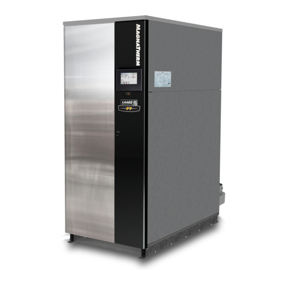
- Page 1 Installation and Operation Instructions Document 1462 Installation and Operation Instructions for MODULATING AND CONDENSING ® 20:1 Turndown. Laars Linc Boiler Model CFH1000 999 MBTU/h Model CFH1500 1,500 MBTU/h Model CFH2000 1,999 MBTU/h Model CFH3000 3,000 MBTU/h FOR YOUR SAFETY: This product must be installed and serviced by a professional service technician, qualified in hot boiler installation and maintenance.
-
Page 2: Table Of Contents
LAARS Heating Systems TABLE OF CONTENTS SECTION 5 Boiler Piping SECTION 1 General Information Introduction ..........5 Water Connections ........26 Cold Water Make-Up ....... 26 Model Identification ........5 Warranty ............ 5 Freeze Protection ........26 Safety Notes..........6 Suggested Boiler Piping Schematics . - Page 3 Section 8 (continued) Configuration ........69 8.E.13 LMV ............102 8.D.1 CH (Central Heat) ......... 69 Messages and USB ......103 8.D.1.a CH1 (Central Heat, One) ....... 70 8.F.1 Messages ..........103 8.F.2 USB Functionality........103 8.D.1.a.1 PID Low........... 71 8.D.1.a.2 PID High ..........
- Page 4 LAARS Heating Systems...
-
Page 5: Section 1 General Information
Page 5 SECTION 1 General Information Model Identification 1.A Introduction Primary information regarding your unit can be found This manual includes information which will help you on the Rating Plate on the outside face of the to install, operate, and maintain the Laars Heating MagnaTherm FT right-side panel. -
Page 6: D Safety Notes
Page 6 LAARS Heating Systems Safety Notes Safety Notes are used thoughout this manual to bring attention to the presence of hazards with various risk levels and to off er important information concering the life of this product. There are 3 basic types. Indicates an imminently hazardous situation which, if not WARNING avoided, can or will result in death or serious injury and can... - Page 7 Page 7 WARNING WARNING The Repair Parts list designates parts that contain Electrical Shock Hazard refractory ceramic fi bers (RCF). RCF has been Electrical shock can cause severe injury, death or classifi ed as a possible human carcinogen. When property damage. Disconnect the power supply before exposed to temperatures above 180ºF, such as during beginning installation or changing the wiring to prevent direct fl ame contact, RCF changes into crystalline silica,...
-
Page 8: Venting Dimensions & Sizing
Page 8 MAGNATHE LAARS Heating Systems Venting Venting Dimensions & Sizing Venting nformation CFT Dimensional Data (inches/(cm) Information Maximum Maximum Typical MODEL Maximum Vent / Air Category IV Category IV Maximum Typical Model Air Pipe Size Ducted Air Pipe Category II Vent Vent / Air Category IV Category IV... - Page 9 30.2 (76.7) (203) (133) (179) (152) (20.9) (152) (188) 1000 80.0 52.4 70.5 60.0 60.0 74.2 30.2 (76.7) (203) (133) (179) (152) (19.7) (153) (188) HERM FT - Dimensional Data 1500 80.0 52.4 70.5 60.0 60.3 74.2 NATHERM FT - Dimensional Data GNATHERM FT - Dimensional Data GNATHERM FT - Dimensional Data AGNATHERM FT - Dimensional Data...
-
Page 10: G Unit Overview
Page 10 LAARS Heating Systems 1.G Unit Overview Pressure Blower Transmitters Heat Exchanger Control Panel On all models, the Control Panel hinges forward for easy access to wiring and to the heat exchanger. Gas Supply Electrical Connection Conduit Air Intake for Field and Filter Wiring... -
Page 11: H Gas Train Components
Page 11 1.H Gas Train Components The Gas Train for all sizes has the same general layout. The only difference between them is the size of the components and piping. Air Damper Air / Fuel Mixer Gas Supply Mounting Bracket Manual Shutoff Gas Solenoid... -
Page 12: I Unpacking And The Install Kit
Page 12 LAARS Heating Systems Unpacking and the Install Kit Locating the Unit This unit may be installed indoors or outdoors. If installing This unit is shipped in a single crate. Carefully outdoors in a location that may experience freezing disassemble the crate and inspect the unit for any temperatures, precautions must be taken to prevent water damage during shipping. -
Page 13: K Clearances
Page 13 1.K Clearances Rear Top Panel is an 24” is required at Top to service the unit. access panel for the servicing of the Ignitor Flame Rod. 11” / 24” at back of unit. Min” Suggested 3” / 12” 3”... -
Page 14: Section 2 Venting And Combustion Air
Page 14 LAARS Heating Systems SECTION 2 Venting and Combustion Air 2.B Vent and Air Pipe Material 2.A General Venting Information This unit requires a special venting system. Refer to WARNING venting supplier’s instructions for complete parts list and Selection of improper vent materials for installations method of installation. -
Page 15: B.1.B Exhaust Vent Terminal
Page 15 a tee with the branch connection sized to allow for insertion of a flue gas analyzer probe. The branch connection must be resealable with a cap or other means to ensure the vent system remains sealed. (See Figure 4) Consideration must be given to the placement and orientation of the flue gas sampling port to ensure that condensate is free to flow back into the unit and not... -
Page 16: C Vent And Air Pipe Sizing
Screen for horizontal PVC air pipe CA012004 CA012001 CA012001 CA012002 CA012003 CA012003 Screen for horizontal polypropylene air pipe CA012200 CA012201 CA012201 CA012202 CA012203 CA012203 Screen for vertical galvanized air pipe D2012204 D2012201 D2012201 D2012202 D2012203 D2012203 Page 16 LAARS Heating Systems CA012403 CA012603 CA012403... -
Page 17: Category Lv Vent Sizes
Page 17 2.C.2 Category II Vent Sizes 2.C.1 Category lV Vent Sizes Positive pressure vent systems may be either Non-positive pressure vent systems are generally vertically terminated. Table 10 gives guidelines for vent horizontally or vertically vented. The vent pipe used and air pipe sizes. -
Page 18: Common Vent Test
Page 18 LAARS Heating Systems 2.C.4 Common Vent Test Au moment du retrait d’une chaudiére existante, les NOTE: This section does not describe a method for common venting this unit. It describes what must be mesures suivantes doivent être prises pour chaque appareil toujurs raccordé... -
Page 19: Combustion Air
Page 19 2.C.5 Combustion Air 2.C.5.a Combustion Air From Room Boilers must have provisions for combustion and In the United States, the most common requirements ventilation air in accordance with the applicable specify that the space shall communicate with the outdoors in accordance with Method 1 or 2. -
Page 20: C.5.B Ducted Combustion Air
Page 20 LAARS Heating Systems 2.C.5.b Ducted Combustion Air 2.D Locating the Vent and Combustion Air The combustion air can be taken through the wall, or Terminals through the roof. The manufacturer offers accessories to use with ducted air systems, as shown in Table 9. 2.D.1 Side-wall Vent Terminal See Table 8 to select the appropriate diameter air pipe. - Page 21 Page 21 *When vent terminal is less than 10 feet (3 m) horizontally from a forced air inlet, the terminal must be at least 3 feet (0.9 m) above the air inlet. (US only) U.S. Installations (see note 1) Canadian Installations (see note 2) A= Clearance above grade, veranda, porch, 12 inches (30 cm) 12 inches (30 cm)
-
Page 22: Side-Wall Combustion Air Terminal
Page 22 LAARS Heating Systems Multiple Vents 2” Min. (Typ) Window OUTLET Multiple Air Intakes 2” Min. (Typ) 36” 12” 84” INLET Terminals must be placed such that they are a Minimum of 12” above the Above expected snow line 12”... -
Page 23: E Outdoor Installation
Page 23 (Place in section 3.5) Model 1000 Model 1500 Model 2000 Model 3000 Air intake screen for unit placed outdoors CA011904 CA011901 CA011901 CA011901 Vent terminal for unit placed outdoors CA017201 CA017202 CA017202 CA017203 Table 11. Air & Vent Accessories for units placed outdoors Table 3** - Air &... -
Page 24: Section 3 Gas Supply And Piping
Page 24 LAARS Heating Systems SECTION 3 Gas supply and Piping 3.A Gas Supply and Piping LP (propane) All Installations must conform to the National Fuel Natural Gas Gas Code ANSI Z223.1/NFPA54, and/or local codes. 4.0 IN - W.C. 8.0 IN - W.C. In Canada, the installation must conform to the latest 10.5 IN - W.C. -
Page 25: Section 4 Water Flow And Headloss Data
Page 25 SCH 40 METAL PIPE CAPACITY FOR 4.B Water Flow 0.60 SPECIFIC GRAVITY NATURAL GAS Natural Gas Undiluted Propa & Headloss Data Pipe Size (in.) NOMINAL PIPE SIZE @ 0.50” W.C. PRESSURE DROP Pipe Size (in. The water flow and headloss data for the Magnatherm Nominal: 2”... -
Page 26: Section 5 Boiler Piping
Page 26 LAARS Heating Systems SECTION 5 Boiler Piping 5.C Freeze Protection 5.A Boiler Water Connections This unit may be installed indoors or outdoors. If NOTE: This unit must be installed in a closed pressure system with a minimum of 12 psi (82.7 kPa) installing outdoors in a location that may experience static pressure at the boiler. -
Page 27: Suggested Boiler Piping Schematics
Page 27 5.D Suggested Boiler Piping Schematics This boiler is a high efficiency appliance. Boiler On innitial installations, drain and flush the system before efficiency can be maximized by using piping and adding propylene glycol. Sludge and other sediments in the distribution configurations that return the lowest boiler can inhibit flow, resulting in rapid breakdown of glycol. - Page 28 Page 28 LAARS Heating Systems 5.D Suggested Boiler Piping Schematics (continued) Single Boiler, P/S Piping for Space Heating with P/S for Indirect Tank Figure 9.
- Page 29 Page 29 Single Boiler, P/S Piping for Space Heating with Parallel Piping for indirect Tank Figure 10.
- Page 30 Page 30 LAARS Heating Systems 5.D Suggested Boiler Piping Schematics (continued) Single Boiler, Variable Primary Space Heating with Parallel Piping for indirect Tank Figure 11.
- Page 31 Page 31 Multiple Boilers, Variable Primary Space Heating with Individual Isolation Valves Figure 12.
- Page 32 Page 32 LAARS Heating Systems Multiple Boilers, P/S Piping for Space Heating and simultaneous Figure 13. DHW heating w/ parallel piped single boiler...
- Page 33 Page 33 Multiple Boilers, P/S Piping for Space Heating with redundant P/S for Indirect Tank Figure 14.
-
Page 34: Water Heating
Page 34 LAARS Heating Systems DHW Heating The MagnaTherm FT must not be used as a direct domestic (potable) water heater. It can be connected to an indirect water heater or heat exchanger to generate domestic (potable) hot water and the boiler’s controller includes indirect water heating logic. - Page 35 Page 35 This page left intentionally blank...
-
Page 36: Section 6 Condensate Drain Trap
Page 36 LAARS Heating Systems SECTION 6 Condensate Drain Trap CAUTION Condensate is mildly acidic (pH=5) and may harm This appliance creates condensation as a by-product of high combustion efficiency. The condensate must some floor drains and/or pipes, particularly those be drained from unit and from the vent system. -
Page 37: Condensate Trap Install Instructions
Page 37 Commercial FT, Condensate Trap Assembly Instructions Document 4378 NPT discharge 1. The discharge hose 'end adapter'. 2. Hose adapter. pipe on boiler 3. Hose clamps (3). 4. Transparent discharge hose. 5. The condensate trap (pre-assembled with cap & fl oat). 6. -
Page 38: Section 7 Electrical Connections
Page 38 LAARS Heating Systems SECTION 7 Electrical Connections 7.B Main Power Connections 7.A Installation Warnings This unit is provided with an electrical junction boxes on the rear panel for main power connections. See CAUTION Figure 18. All power wires are factory installed The supply voltage to this unit must not be between this junction box and the main high voltage disconnected, except for service or isolation, or... -
Page 39: Main Power Connections
Page 39 Flex Conduit for Field Wiring Field Electrical Connections at the Terminal Block on the Control Panel Hinged Control Panel swings open for servicing and setup Low Voltage Box for Field Connections High Voltage Box for Main Power Connections Available Knockouts for other wiring needs VIEW from... -
Page 40: Control Panel Layout
Page 40 LAARS Heating Systems 7.D Control Panel Layout LMV Controller Assembly Handset, Display and Low Water Cut-Off Operating Unit. For Certified and Trained Field Techs Only. 12 Volt DC Power Supply Linc Controller Assembly Field Connections Terminal Block O2 Sensor Controller RUN RELAY CASCADE... -
Page 41: Temperature Sensors
Page 41 maximum. DHW pump functionality is configured using the touch screen. System Pump - If connecting a system pump, use terminals 29 and 30. As this is a dry contact, the system pump supply voltage or system pump relay coil voltage would be applied at terminal 29, and when the system pump is activated, power will be available at terminal 30. -
Page 42: Isolation Valve
Page 42 LAARS Heating Systems NOTE: When running the Power and Field WARNING Connection wires (Lead Lag, System Sensor, Electrical Shock Hazard Outdoor Sensor, Building Automation, etc.), it Electrical shock can cause severe injury, death or is helpful to exit and enter the units through the property damage. -
Page 43: Rs 485 For Cascade (Lead Lag)
Page 43 Figure 22. Jumper locations at the inputs 7.E.9 RS 485 for Cascade (Lead Lag) Section 8.D.11.d on page 94 shows how these Cascade - Prior to wiring units for cascade operations, systems are configured in the touchscreen controls. select one unit as the lead boiler. -
Page 44: Modbus To Bacnet Memory Map
Page 44 LAARS Heating Systems Modbus to BACnet Memory Map Modbus BACnet BACnet Address Type Map Descriptor Name Data Type Object ID Notes Read Inlet Sensor Read °C/°F °C/°F Read Outlet Sensor Read °C/°F Read Flue Sensor Read Read DHW Sensor Read °C/°F Read System Inlet Sensor Read °C/°F °C/°F Read System Outlet Sensor Read... - Page 45 Page 45 Modbus BACnet BACnet Address Type Map Descriptor Name Data Type Object ID Notes HIGH DELTA‐T ERROR = 42 FAN SPEED ERROR = 43 0 = Lockout 2 = Safety 10 = Home Run Position 12 = Burner Standby 22 = Combustion Fan, SV On 24 = Drive to Prepurge Position 30 = Prepurge 35 = VSD Drive to Ignition Position 36 = Drive to Ignition Position 38 = Preignition (Spark) On 40 = Pilot Vlave On 42 = Ignition (Spark) Off 44 = Interval 1 (Pilot Stabilization) 50 = Safety Time 2 52 = Interval 2 (Main Stabilization) 60 = Operation 1 (Normal Operation) Read LMV_Phase Read 62 = Operation 2 (Driving to Low Fire) 64 = Drive to Ignition Position 65 = Interval 2 66 = Ignition (Spark) + Pilot Valve On 67 = Main Valve Off 68 = Pilot Waiting Time 69 = Pilot Waiting Time ‐ Startup (Interval 1) 70 = Afterburn Time 72 = Drive to Postpurge Position 74 = Mandatory Postpurge 78 = Optional Postpurge...
- Page 46 Page 46 LAARS Heating Systems 7.F Modbus and BACnet memory Map (continued) Modbus BACnet BACnet Address Type Map Descriptor Name Data Type Object ID Notes Bit 2 = Not used Bit 3 = Not used Bit 4 = Ignition Bit 5 = Start signal/DW valve Bit 6 = Fan Bit 7 = Oil pump/magnetic coupling Read LMV‐Outputs Read Bit 8 = Fuel valve SV oil Bit 9 = Fuel vlave V1 oil Bit 10 = Fuel valve V2 oil Bit 11 = Fuel valve V3 oil Bit 12 = Fuel valve SV gas Bit 13 = Fuel valve V1 gas Bit 14 = Fuel valve V2 gas Bit 15 = Fuel valve PV gas Refer to LMV Manual Read LMV‐Burner ID Read ...
- Page 47 Page 47 Modbus BACnet BACnet Address Type Map Descriptor Name Data Type Object ID Notes 5 = Start 24 = Error Block 160 = Standby 165 = Check Safety Swtich 166 = Run 177 = Prepurge Open 181 = Parameter Block 183 = Lockout Read Burner Status 1 Read 188 = Testmode 194 = Prepurge Closed 195 = Wait for HIS Free 196 = HIS Preheat/Prespark 200 = Verify Primary SF 217 = interpurge 241 = Postpurge 245 = Trial for Ignition 250 = Trial for Ignition Main 52=Post Purge Read LMV ‐ Lower Trim Limit Read (See LMV Manual) Read LMV ‐ Upper Trim Limit Read (See LMV Manual) Read LMV ‐ Current Trim Read...
-
Page 48: Wiring Diagram
Page 48 LAARS Heating Systems 7.G WiringDiagram X3-05 X6-03 X4-02 X7-02 X9-04 X5-01 X5-02 X3-03 Display Figure 23. Wiring Diagram, Models 1000 - 3000... - Page 49 Page 49 S2A MODULE TB1-6:3 TB1-9:3 BK/O TB1-12:1 O2 Sensor WIRING DIAGRAM DWG# E23993 REV A 1.0 - 3.0 CFT NOTE: All wiring diagrams and ladder diagrams specific to this unit are located on the inside left front door panel. LABEL# H2406600 DOCUMENT# H2406700...
-
Page 50: High Voltage Wiring Diagrams
Page 50 LAARS Heating Systems 7.H High Voltage Wiring Diagrams Figure 24. High Voltage Wiring Diagram 120V, Single Phase... - Page 51 Page 51 120V N 120V N 120V H 120V H 120V N 120V N 120V H 120V H Figure 25. High Voltage Wiring Diagram 208V / 240V Single Phase...
- Page 52 Page 52 LAARS Heating Systems 7.H High Voltage Wiring Diagrams (continued) 120V N 120V N 120V H 120V H 120V N 120V N 120V H 120V H Figure 26. High Voltage Wiring Diagram 208V / 489V, Three Phase...
- Page 53 Page 53 Figure 27. High Voltage Wiring Diagram 600V, Three Phase...
-
Page 54: Ladder Diagrams
Page 54 LAARS Heating Systems Ladder Diagrams 120VAC (1PH/60Hz) PRESSURE TRANSMITTER - 1 PWM SIGNAL PRESSURE 1 2 4 5 TRANSMITTER - 2 BLOWER TB1-120L TB1-120N CONVENIENCE OUTLET TB1-GND POWER SWITCH TB1-120L TB1-120N TERMINAL STRIP 120VAC BLOWER CONTACTOR 120VAC 24VAC TRANSFORMER TB1-24V TB1-24N TERMINAL STRIP 24VAC... - Page 55 Page 55 PRESSURE X22-2 TRANSMITTER - 1 (continued) PWM SIGNAL PRESSURE X22-1 X21-1 TRANSMITTER - 2 X9-1 BLOWER LMV BURNER CONTROLLER TB1-120L X3-04-5 TB1-120N X3-04-4 CONTROLLER POWER TB1-GND X3-04-3 POWER SWITCH X3-04-2 TERMINAL STRIP 120VAC X3-04-1 SAFETY CHAIN IS SATISFIED BLOWER CONTACTOR X5-03-4 X5-03-2...
- Page 56 Page 56 LAARS Heating Systems Ladder Diagrams (continued) 208/240VAC (1PH/60Hz) PRESSURE TRANSMITTER - 1 PWM SIGNAL 1 2 4 5 PRESSURE TRANSMITTER - 2 BLOWER TB1-120L 120VAC TRANSFORMER TB1-120N 120VAC TB1-GND CONVENIENCE OUTLET POWER SWITCH TB1-120L TB1-120N TERMINAL STRIP 120VAC VFD CONTACTOR 120VAC 24VAC TRANSFORMER...
- Page 57 Page 57 PRESSURE X22-2 TRANSMITTER - 1 PWM SIGNAL (continued) PRESSURE X22-1 X21-1 TRANSMITTER - 2 BLOWER X9-1 LMV BURNER CONTROLLER TB1-120L X3-04-5 120VAC TRANSFORMER TB1-120N X3-04-4 CONTROLLER POWER TB1-GND X3-04-3 X3-04-2 POWER SWITCH X3-04-1 SAFETY CHAIN IS SATISFIED TERMINAL STRIP 120VAC X5-03-4 X5-03-2 VFD CONTACTOR...
- Page 58 Page 58 LAARS Heating Systems Ladder Diagrams (continued) 208/480 (3PH/60Hz) L2 L3 PRESSURE PWM SIGNAL TRANSMITTER - 1 1 2 4 5 PRESSURE BLOWER TRANSMITTER - 2 TB1-120L 120VAC TRANSFORMER TB1-120N 120VAC TB1-GND CONVENIENCE OUTLET POWER SWITCH TB1-120L TB1-120N TERMINAL STRIP 120VAC VFD CONTACTOR 120VAC 24VAC TRANSFORMER...
- Page 59 Page 59 PRESSURE PWM SIGNAL X22-2 TRANSMITTER - 1 (continued) PRESSURE BLOWER X22-1 X21-1 TRANSMITTER - 2 X9-1 LMV BURNER CONTROLLER TB1-120L X3-04-5 120VAC TRANSFORMER TB1-120N X3-04-4 CONTROLLER POWER TB1-GND X3-04-3 X3-04-2 POWER SWITCH X3-04-1 SAFETY CHAIN IS SATISFIED TERMINAL STRIP 120VAC X5-03-4 X5-03-2 VFD CONTACTOR...
- Page 60 Page 60 LAARS Heating Systems Ladder Diagrams (continued) 600 (3PH/60Hz) L2 L3 PRESSURE PWM SIGNAL TRANSMITTER - 1 1 2 4 5 PRESSURE BLOWER TRANSMITTER - 2 TB1-120L 120VAC TRANSFORMER TB1-120N 120VAC TB1-GND CONVENIENCE OUTLET POWER SWITCH TB1-120L TB1-120N TERMINAL STRIP 120VAC VFD CONTACTOR 120VAC 24VAC TRANSFORMER...
- Page 61 Page 61 PRESSURE PWM SIGNAL X22-2 TRANSMITTER - 1 (continued) PRESSURE BLOWER X22-1 X21-1 TRANSMITTER - 2 X9-1 LMV BURNER CONTROLLER TB1-120L X3-04-5 120VAC TRANSFORMER X3-04-4 TB1-120N CONTROLLER POWER TB1-GND X3-04-3 X3-04-2 POWER SWITCH X3-04-1 SAFETY CHAIN IS SATISFIED 120N TERMINAL STRIP 120VAC X5-03-4 X5-03-2...
-
Page 62: Section 8 Control Operation
Page 62 LAARS Heating Systems SECTION 8 Control Operation 8.A The Home Screen CSP: is the Calculated (and Current) Set Point. It can be based on the CH1 (Central Heat One), CH2, or the DHW (Domestic Hot Water) setpoint, depending on the model and the installation set up and may be adjusted by the Outdoor Reset and the DHW... -
Page 63: Keypad Operations
Page 63 Keypad Operations 8.A.2 NOTE: You can always tell exactly where you have navigated to by looking at the icons in the Navigation Bar. In this example you are in Home / Configure / Central Heat / Central Heat One Shows the current setting of the Parameter. -
Page 64: Login To Lock / Unlock The Screen
Page 64 LAARS Heating Systems 8.B Login to Lock / Unlock the Display Screen Password Protection: To change configuration or parameters, a password is required. The control system includes three levels of password protection. Touch the 'Current Lock Status' icon at the top of the screen. USER password is lhs. -
Page 65: Quick Start
Q U I C K S T A R T Page 65 8.C Quick Start Quick Start will allow a user to configure the BASIC functionality of the control, without going through all of the parameters that are available. The 6 BASIC functionalites at Quick Start are •... -
Page 66: Ch1 (Central Heat, One) 1
Q U I C K S T A R T Page 66 LAARS Heating Systems 8.C.1.a CH1 (Central Heat, One) • Enable/Disable – This allows CH1 to be enabled/disabled. The default setting is Enabled. • Set Point – This is the set point temperature. 8.C.1.b CH2 (Central Heat, Two) To navigate to the CH2 Quick Start Screen, touch the CH2 Icon on the CH Quick Start Selection Screen. -
Page 67: Outdoor Reset
Q U I C K S T A R T Page 67 8.C.3 Outdoor Reset Outdoor reset adjusts a boiler’s setpoint based on outdoor air temperature. This is for boilers only, and is not used for domestic water. To navigate to the Outdoor Quick Start Screen, touch the Outdoor Icon on the Quick Start Screen. The Outdoor Quick Start Screen allows the adjustment of the following parameters: •... -
Page 68: Anti-Short Cycle
Q U I C K S T A R T Page 68 LAARS Heating Systems 8.C.5 Anti-Short Cycle To navigate to the Anti-Short Cycle Quick Start Screen, touch the Anti-Short Cycle Icon on the Quick Start Screen. The Anti-Short Cycle Quick Start Screen allows adjustment of the following parameter: •... -
Page 69: D Configuration
C O N F I G U R A T I O N Page 69 8.D Configuration This area of the controller allows access to all parameters available, based on the access level that is unlocked. To navigate to the Configuration Screen, touch the Configure Icon in the lower left portion of the Home Screen. CSP: is the Calculated (and Current) Set Point. -
Page 70: Central Heat)
C O N F I G U R A T I O N Page 70 LAARS Heating Systems 8.D.1 CH (Central Heat) “CH” stands for “Central Heat.” It is used for space heating demands. On the Configure Screen, touch the CH thermometer icon to navigate to the CH Selection Screen There are two identical heat demands, CH1 and CH2, each with independent control algorithms and independent inputs on the input... -
Page 71: D.1.A.1 Pid Low
C O N F I G U R A T I O N Page 71 PID Low 8.D.1.a.1 Note that in most cases, PID parameters will not need to be changed. The PID Parameters Screen allows adjustment to the following parameters: •... -
Page 72: Dhw (Domestic Hot Water)
Page 72 LAARS Heating Systems 8.D.2 DHW (Domestic Hot Water) To navigate to the DHW Screen, touch the DHW faucet icon on the Configure Screen. DHW has all the same parameters as CH1 and CH2 with one exception. DHW has the following additional parameters for adjustment: •... -
Page 73: Outdoor Reset
C O N F I G U R A T I O N Page 73 8.D.3 Outdoor Reset Outdoor reset adjusts a boiler’s setpoint based on outdoor air temperature. This is for boilers only, and is not used for domestic water. The Outdoor Parameters Screen allows the adjustment of the following parameters: •... -
Page 74: Cascade (All About Lead / Lag)
Page 74 LAARS Heating Systems 8.D.4 Cascade (All about Lead / Lag) An installation with two or more units may be configured for cascade operation. Up to eight units can be cascaded and controlled together. To navigate to the Cascade Screen, touch the Cascade Icon on the Configuration Screen. The Cascade Screen provides four navigation icons to configure the system for cascade operations. - Page 75 C O N F I G U R A T I O N Page 75 Log In Settings Parameter User Installer Default Unit Base Load Drop Load Min On Time Seconds Min Off Time Seconds Table 19. Parameter Settings minimum (instead of the allowable minimum firing rate of 5%). In addition, if the Drop Load Value is higher than the minimum firing rate of the unit, the unit will turn off at the Drop Load Value and not the minimum firing rate of the unit.
- Page 76 Page 76 LAARS Heating Systems As the load increases: As the load decreases: • Until all units are firing, no unit is requested to exceed • As long as all units are firing – the base load value can the base load value. be exceeded, as long as all units maintain the same firing rate.
- Page 77 C O N F I G U R A T I O N Page 77 About Cascading (Lead / Lag) -continued Low demand: The first boiler in sequence ignites and gradually increases firing rate to satify the heat demand. Increased demand: Once the first boiler reaches the Base Load Value (40%) firing rate, the second boiler ignites.
- Page 78 eight boilers reach the Base Load Value , all units are allowed to increase firing rate (same at all boilers) up to C O N F I G U R A T I O N Page 78 LAARS Heating Systems maximum firing rate.
-
Page 79: D.4.A Cascade Parameters
C O N F I G U R A T I O N Page 79 8.D.4.a Cascade Parameters To navigate to the Cascade Parameters Screen, touch the Cascade Icon on the Configuration Screen, then touch the Cascade Parameters Icon. The Cascade Parameters Screen allows adjustment of the following parameters: •... -
Page 80: D.4.A.1 Base / Drop Load
C O N F I G U R A T I O N Page 80 LAARS Heating Systems Base / Drop Load 8.D.4.a.1 Base Load – Is the firing rate that must be achieved prior to adding another unit to satisfy the heat demand. Drop Load –... -
Page 81: D.4.B Rotation
C O N F I G U R A T I O N Page 81 8.D.4.b Rotation To navigate to the Cascade Rotation Screen, touch the Cascade Icon on the Configure Screen, then touch the Rotation Icon on the Cascade Configuration Screen. The Cascade Rotation Screen is a view only screen. -
Page 82: D.4.C Redundancy
C O N F I G U R A T I O N Page 82 LAARS Heating Systems 8.D.4.c Redundancy To navigate to the Cascade Redundancy Screen, touch the Cascade Icon on the Configuration Screen, then touch the Redundancy Icon on the Cascade Configuration Screen. The Cascade Redundancy Screen allows the selection of one of three options for redundancy in cascade systems. -
Page 83: Pumps
C O N F I G U R A T I O N Page 83 8.D.5 Pumps The Pump Configuration Screen allows adjustment of the following 7 parameters: • Boiler Pump Control – This parameter provides the ability to set the boiler pump functionality to be: Auto –... -
Page 84: D.5.A Vari-Prime
C O N F I G U R A T I O N Page 84 LAARS Heating Systems 8.D.5.a VARI-PRIME ® The Vari-Prime Screen allows the adjustment of the following parameters: • On Delay – Upon a call for heat, once the unit ignites, this is the amount of time the unit will wait prior to modulating the pump speed. -
Page 85: Temp Limits
C O N F I G U R A T I O N Page 85 8.D.7 Temp Limits To navigate to the Temp Limits Screen, touch the Temp Limits Icon on the Configuration Screen. The Temp Limits Configuration Screen allows adjustment of the following parameters: •... -
Page 86: D.7.B Flue Limitation Parameters
C O N F I G U R A T I O N Page 86 LAARS Heating Systems 8.D.7.b Flue Limitation Parameters To navigate to the Flue Limitation Parameters Screen, touch the Temp Limits Icon on the Configuration Screen, then touch the Flue Limitation button on the Temperature Limits Parameters Screen. -
Page 87: External
C O N F I G U R A T I O N Page 87 8.D.8 External The External Configuration Screen applies to the 0-10VDC (4-20mA) analog input BAS signal, and allows adjustment of the following parameters: To navigate to the External Configuration Screen, touch the External Icon on the Configuration Screen. •... -
Page 88: D.8.A External - Remote Set Point
C O N F I G U R A T I O N Page 88 LAARS Heating Systems 8.D.8.a External – Remote Set Point External (0 – 10VDC or 4 – 20mA) • An External heat demand can be initiated by a Building Automation System (BAS) using a 0-10VDC or 4-20mA signal. -
Page 89: D.8.B External Firing Rate
C O N F I G U R A T I O N Page 89 8.D.8.b External Firing Rate With External Firing Rate selected, the unit will initiate a heat demand once the analog input signal exceeds the Demand On value. Once the demand is initiated, the analog input signal must be lower than Demand Off to remove the heat demand. -
Page 90: Miscellaneous Features
C O N F I G U R A T I O N Page 90 LAARS Heating Systems 8.D.10 Miscellaneous Features To navigate to the Miscellaneous Features Screen, touch the Miscellaneous Features Icon on the Configuration Screen. The Miscellaneous Features screen provides navigation for the following items: •... -
Page 91: D.10.A Demands Priorities
C O N F I G U R A T I O N Page 91 8.D.10.a Demands Priorities To navigate to the Demands Priorities Screen, first go to the Miscellaneous folder. At the Demands Priorities screen select each configured demand and assign a priority number. Remember to always save the new setting with the button. -
Page 92: D.10.C Warm Weather
C O N F I G U R A T I O N Page 92 LAARS Heating Systems 8.D.10.c Warm Weather To navigate to the Warm Weather Configuration Screen, touch the Miscellaneous Features on the Configuration Screen, then touch the Warm Weather Icon on the Miscellaneous Features screen. The Warm Weather Configuration Screen allows adjustment of the following parameters: •... -
Page 93: D.10.D Com Port, Bms
C O N F I G U R A T I O N Page 93 8.D.10.d COM Port, BMS The control has Modbus and BACnet MSTP (RS485) protocols on board, for use with Building Management Systems. Gateways can be used for other communication protocols. To navigate to the COM Port Configuration Screen, touch the Misc Icon on the Configuration Screen, then touch the COM Port Icon on the Misc Configuration Screen. -
Page 94: D.10.E Temperature Conversion
C O N F I G U R A T I O N Page 94 LAARS Heating Systems 8.D.10.e Temperature Conversion To navigate to the Temperature Conversion Configuration Screen, touch the Temperature Conversion Icon on the Miscellaneous Features screen. The Temperature Conversion Configuration Screen allows adjustment of the following parameter: •... -
Page 95: D.10.G Trim (O2 Trim Enable / Disable)
C O N F I G U R A T I O N Page 95 8.D.10.g Trim (O 2 Trim Enable / Disable) To navigate to the Trim Menu, touch the Trim Icon on the Miscellaneous Menu Screen. This O 2 Trim Menu allows you to •... - Page 96 Page 96 LAARS Heating Systems Isolation Valve - Single Boiler Operation Disabled – if the isolation valve functionality is disabled, via the display, the isolation valve output will not actuate, and the boiler will ignore the status of the limit switch inputs. Enabled –...
-
Page 97: D.10.H Isolation Valve
Page 97 open, to avoid dead heading the system pump. Additional isolation valves may also be open, based on the value of “Min. # of Open Valves”. vi. As the cascade rotation functionality rotates which boiler fires first to satisfy a heat demand, the open limit switch of the new boiler that will fire first must be open prior to closing the isolation valve of the previous boiler that was in the sequence to fire first. -
Page 98: E Service Screens
S E R V I C E Page 98 LAARS Heating Systems 8.E Service Screens To navigate to the Service Screen, touch the Service Icon in the lower left portion of the Home Screen. Available only to the factory or technician qualified at the OEM level. -
Page 99: Digital I/O ( Input / Output )
S E R V I C E Page 99 8.E.2 Digital I/O ( Input / Output ) There are two screens associated with the Digital I/O: Digital I/O Screen-Inputs; Digital I/O Screen-Outputs. Navigate to the Digital I/O Screen by touching the Digital I/O Button on the Service Screen. Digital I/O Inputs: The indicator light associated with the input is green when the input is satisfied. -
Page 100: Analog I/O
S E R V I C E Page 100 LAARS Heating Systems 8.E.3 Analog I/O Navigate to the Analog I/O Screen by touching the Analog I/O Button on the Service Screen. There are two screens associated with the Analog I/O: Analog I/O Inputs; Analog I/O Outputs. Analog I/O Input: There are three types of analog inputs;... -
Page 101: Screen Settings Timeout
S E R V I C E Page 101 8.E.4 Screen Settings Timeout Navigate to Screen Settings by touching the Screen Button on the Service Screen. There are two adjustable screen settings: Light Timeout and AutoLock Timeout. • Light Timeout allows the user to adjust the amount of time the touch screen backlight will remain lit after user interaction has ceased. -
Page 102: Factory Reset
S E R V I C E Page 102 LAARS Heating Systems 8.E.7 Factory Reset Touching the Factory Reset Button on the Service Screen resets all touch screen adjustable parameters back to the factory default setting. 8.E.8 HMI Model OEM only 8.E.9 BIC Model OEM only... -
Page 103: Messages And Usb
Page 103 Messages and USB Messages 8.F.1 Messages The ‘Messages’ icon at the bottom of the home screen displays an ‘Exclamation Point’ when messages are present. Press the icon to see the message(s). 8.F.2 USB Functionality The USB port is on the back of the display. To access it, open both panels and look for the black USB cable extending from the back of the display. -
Page 104: Active Demands
Page 104 LAARS Heating Systems 8.G Active Demands The Active Demand Window indicates the status of active heat demands. Sec�on 6.5 Ac�ve Demands A black heat demand icon indicates the heat demand that is currently being satisfied. A “greyed out” heat demand icon is either lower in priority than the heat demand that is currently being satisfied, or the heat demand has reached Ac�ve Demand Bar set point, but remains active. -
Page 105: Section 9 Parameter Tables
Page 105 SECTION 9 Parameter Tables Table 21. CFH Parameter and Range Table (includes next 2 pages) Time & Date Time & Date Hour Hour Hour Hour Minute Minute Minute Minute Month Month Month Month Year Year Year Year CH1 Enable/Disable CH1 Enable/Disable Enable Enable... - Page 106 Page 106 LAARS Heating Systems Pump Configuration Pump Configuration Auto/ Always On/ Off Auto/ Always On/ Off Auto Auto Boiler Pump Control Boiler Pump Control Disable Disable During DHW During DHW Boiler Pump Post Circulation Boiler Pump Post Circulation Seconds Seconds Auto Auto...
- Page 107 Page 107 Summer Kick Isolation Valve Summer Kick Isolation Valve Seconds Seconds 1440 1440 Summer Kick Period Summer Kick Period 2000 2000 Minute Minute Anti- Short Cycle Time Anti- Short Cycle Time Cycle Time Cycle Time Seconds Seconds Temperature Conversion Temperature Conversion Fahrenheit Fahrenheit...
-
Page 108: Section 10 Initial Startup Instructions
Page 108 LAARS Heating Systems SECTION 10 Initial startup Instructions 10.A Filling the Boiler System 1. Ensure the system is fully connected. Close all 12. Check the gauge for correct water pressure and bleeding devices and open the make-up water also check the water level in the system. -
Page 109: Initial Operation
Page 109 10.B Initial Operation WARNING The initial setup must be checked before the unit is Improper adjustment may lead to poor combustion put into operation. Problems such as failure to start, quality, increasing the amount of carbon monoxide rough ignition, strong exhaust odors, etc. can be due produced. -
Page 110: Combustion Setup Procedure Hi-Fire, Low-Fire
Page 110 LAARS Heating Systems 10.B.2 Combustion Setup Procedure Hi-Fire, Low-Fire The gas system must be set up properly, so the boiler will run efficiently throughout its modulation range under the installed conditions. This setup should only be performed by a factory trained technician. 1. - Page 111 Page 111 Gas Type Maximum CO (ppm) Model High-Fire CO 2 Low-Fire CO 2 Greater than 8.0% 9.0% +/- 0.2% All Models Natural & less than 9.2% Table 22. Combustion Settings. LP (propane) Natural Gas 8. If needed, adjust the fuel pressure adjustment 4.0 IN - W.C.
-
Page 112: Shutting Down The Unit
Page 112 LAARS Heating Systems 10.E Controllers 10.C Shutting Down the Unit This step must be performed by a qualified service person. This unit utilizes three (3) separate controllers to manage system functions, burner management and air/ Turn off the main electrical disconnect switch. fuel ratio control: Close all manual gas valves. -
Page 113: Pressure Transmitters
Page 113 10.F Transmitters This unit utilizes a pair of pressure transmitters to determine that the pressure drop across the combustion air/flue gas side of the system is within acceptable bounds for proper operation. If during operation the differential pressure across the system exceeds a predetermined value at a given firing rate, the system will shut down and a “Burner An Pressure Error”... -
Page 114: Section 11 Maintenance
Page 114 LAARS Heating Systems SECTION 11 Maintenance 11.A System Maintenance 11.B Maintenance Notes Do the following once a year: Use only genuine manufacturers replacement parts. Lubricate all the pumps in the system, per the CAUTION instructions on the pump. When servicing the controls, label all wires before Inspect the venting system for obstruction or disconnecting them. -
Page 115: Controller
Page 115 the mounting bracket must be grounded to the boiler installed the cables should be properly coiled and secured and reconnected to the LMV. chassis. To remove the spark ignition electrodes, shut off the power to the unit, turn off the main gas supply In the event of failure of the on/off Honeywell solenoid, the entire valve must be replaced. -
Page 116: Heat Exchanger Tubes
Page 116 LAARS Heating Systems 11.B.7 Heat Exchanger Tubes 8. To place the unit back in operation, install all Black carbon soot build-up on the internal surfaces removed components in the reverse order. Be sure of the heat exchanger is caused by one or more of all gaskets are in place as the components are the following: incomplete combustion, combustion air installed. -
Page 117: Oxygen Sensor
Page 117 11.B.10 Oxygen Sensor HIGH LIMIT SWITCHES The oxygen sensor is an automotive derived sensor which will require periodic replacement. If the sensor fails or is out of calibration the Oxygen and Carbon Monoxide lines on the main menu will blink red and dashes will be displayed instead of numeric values. -
Page 118: Section 12 Troubleshooting
Page 118 LAARS Heating Systems SECTION 12 Troubleshooting 12.A Lockouts and Errors. Condition Information Corrective Action • • Flow Switch Insufficient flow at the outlet of the Faulty boiler/heater pump – replace pump. • boiler/heater Faulty pump contactor – replace contactor. •... - Page 119 Page 119 Condition Information Corrective Action • • Flow Switch Insufficient flow at the outlet of the Faulty boiler/heater pump – replace pump. 2463 4937 • boiler/heater Faulty pump contactor – replace contactor. 1739 3489 • • Auto-reset Condition Blown boiler/heater pump fuse – replace fuse F14 on the 1253 2514 •...
-
Page 120: Lmv Errors
Page 120 LAARS Heating Systems 12.B LMV Errors. In addition to the error messages displayed on the display unit, the LMV Status menu provides an Error Code and corresponding Diagnostic Code associated with failures of the LMV controller. The following table provides an abbreviated list of common LMV errors and corrective actions. - Page 121 Page 121 Error Diag. Meaning for the LMV3 Corrective Action Code Code Note: Diagnostic codes are additive. If a diagnostic code appears that is not on this list, it is a combination of multiple diagnostic codes. Standardization timed out because the VSD took too long to ramp down Timeout of standardization (VSD ramp down time too long) at the end of the standardization.
- Page 122 Page 122 LAARS Heating Systems Error Diag. Meaning for the LMV3 Corrective Action Code Code Note: Diagnostic codes are additive. If a diagnostic code appears that is not on this list, it is a combination of multiple diagnostic codes. No speed signal was detected. 1) Ensure that the motor is rotating.
- Page 123 Page 123 Error Diag. Meaning for the LMV3 Corrective Action Code Code Note: Diagnostic codes are additive. If a diagnostic code appears that is not on this list, it is a combination of multiple diagnostic codes. Verify that the valve connected to the fuel actuator is not bound. Ensure Position error that the torque requirements of the valve are less than the output of the fuel actuator.
-
Page 124: Section 13 Replacement Parts
Page 124 LAARS Heating Systems SECTION 13 Replacement Parts Use only genuine Manufacturer replacement parts. To order or purchase parts, contact your nearest manufacturers dealer or distributor. (See the back cover of this manual for the manufacturers website). 13.A Frame and Jacket Assembly, Part Numbers SEAL LOCATED UNDERNEATH BURNER DOOR... - Page 125 Page 125 1000 1500 2000 3000 ITEM DESCRIPTION PART NO. PART NO. PART NO. PART NO. HEAT EXCHANGER ASSEMBLY R10T2000 R15T2000 R20T2000 R30T2000 E2389700 LOW AIR PRESSURE SENSOR, SHINEUI SENSOR, OXYGEN (LAMBDA), BOSCH LSU 4.9 E2376700 DISPLAY, TOUCH SCREEN, 7 IN DIAG, HTD E2399200 RE2322700 SWITCH, ROCKER...
-
Page 126: Control Panel Assembly Part Numbers
Page 126 LAARS Heating Systems 13.B Control Panel Assembly, Part Numbers ALL SIZES ITEM DESCRIPTION PART NO. CONTROLLER ASSY, O2 SENSOR 30N7089 PANEL ASSY, CONTROL, SHEET METAL 30N7092 CABLE, DIAGNOSTIC HANDSET, 7 FT LONG E2393000 CONTROLLER ASSY, LAARS LINC ® 30T7096 LABEL, CONTROL PANEL, MGT H2363500... -
Page 127: Blower And Burner Assembly
Page 127 13.C Blower and Burner Assembly, Part Numbers. ALL Sizes Blower Gas-Air Mixer Part Numbers 1.0 & 1.5 = Blower Identified in High Voltage Box Parts Listing Blower & Air-Gas Mixer, CFT 1.0 - 3.0 ITEM PART NO./BOILER SIZE DESCRIPTION 300S5039 O-RING, OUTLET, ACTUATOR... -
Page 128: Ac Distribution Box Assemblies
Page 128 LAARS Heating Systems 13.D AC Distribution Box Assemblies and Part Numbers VOLTAGE & PHASE BOILER ITEM# DESCRIPTION SIZE 120V 1Ø 208V 1Ø 240V 1Ø 208V 3Ø 480 3Ø 600V 3Ø 20N7311 SUPPORT, BOX, AC DISTRIBUTION, MGT 20N7312 BOX, AC DISTRIBUTION, MGT 20N7313 COVER, BOX, AC DISTRIBUTION, MGT 15T7317... - Page 129 Page 129 SINGLE PHASE 1Ø 208/240V 1Ø 120V 1Ø HX 1.0,1.5,2.0 HX 1.0,1.5,2.0 THREE PHASE 3Ø BOILER SIZE 208/480V 3Ø 600V 3Ø HX 2.0,3.0 HX 2.0,3.0 1.0 - 1.5...
-
Page 130: Burner Door Part Numbers
Page 130 LAARS Heating Systems 13.E Burner Door Part Numbers Burner Door Part Numbers DETAIL A SCALE 1 : 1.5 Burner Door Parts, CFT 1.0 - 3.0 ITEM PART NO./BOILER SIZE DESCRIPTION GASKET, OUTPUT, BLOWER S2135300 15T5080 30T5080-1 TRANSITION ASSY, BLOWER S2136300 S2136400 GASKET, BURNER... -
Page 131: Waterway Inlet Assy, Part Numbers
INLET WATERWAY Outlet Waterway Part Numbers (Part of Boiler Page 131 Weldment) 13.F Waterway Inlet Assembly, Part Numbers Inlet Waterway Part Numbers Item # Description Part Number Sensor, Water Temp, 10K E2395600 Grommet, Pipe, Rubber S2114000 Plug, 1/4" NPT P2014200 Plug, 1/2"... -
Page 132: Waterway Outlet Assy, Part Numbers
13.H Gas Train Part Numbers GAS TRAIN PARTS, CFT 1.0 - 3.0 ITEM PART NO./BOILER SIZE DESCRIPTION V2025500 V2025600 VALVE-ACTUATOR ASSY, GAS, VA SERIES, VKG V2025400 ACTUATOR, ELECTRO-HYDRAULIC, SKP25.011U1 V2025200 V2015900 V2025300 BODY, VALVE, GAS V2026200 VALVE, GAS, SOLENOID, NC SAFETY SHUTOFF V2026400 Exhaust Manifold Part Numbers R2004000...
Need help?
Do you have a question about the Laars Linc MagnaTherm FT CFH1000 and is the answer not in the manual?
Questions and answers