Bradford White Brute BNTH Installation And Operation Instructions Manual
Modulating boiler
Hide thumbs
Also See for Brute BNTH:
- User manual (12 pages) ,
- Installation and operation instructions manual (92 pages) ,
- User manual (16 pages)
Table of Contents
Advertisement
Quick Links
Installation and Operation Instructions
FOR YOUR SAFETY: This product must be installed and serviced by a professional service technician,
qualified in hot water boiler and heater installation and maintenance. Improper installation and/or operation
could create carbon monoxide gas in flue gases which could cause serious injury, property damage, or
death. Improper installation and/or operation will void the warranty.
WARNING
If the information in this manual is not
followed exactly, a fire or explosion may
result causing property damage, personal
injury or loss of life.
Do not store or use gasoline or other
flammable vapors and liquids in the vicinity
of this or any other appliance.
WHAT TO DO IF YOU SMELL GAS
• Do not try to light any appliance.
• Do not touch any electrical switch; do not
use any phone in your building.
• Immediately call your gas supplier from a
nearby phone. Follow the gas supplier's
instructions.
• If you cannot reach your gas supplier, call
the fire department.
Installation and service must be performed
by a qualified installer, service agency, or gas
supplier.
Installation and Operation
Instructions for
Brute
TM
Modulating Boiler
Model BNTH
Sizes 080–210 MBTU/h
AVERTISSEMENT
Assurez-vous de bien suivres les instructions
données dans cette notice pour réduire au
minimum le risque d'incendie ou d'explosion
ou pour éviter tout dommage matériel, toute
blessure ou la mort.
Ne pas entreposer ni utiliser d'essence ni
d'autres vapeurs ou liquides inflammables dans
le voisinage de cet appareil ou de tout autre
appareil.
QUE FAIRE SI VOUS SENTEZ UNE ODEUR DE GAZ:
• Ne pas tenter d'allumer d'appareils.
• Ne touchez à aucun interrupteur. Ne pas vous
servir des téléphones dansle bâtiment où vous
vous trouvez.
• Appelez immédiatement votre fournisseur de
gaz depuis un voisin. Suivez les instructions
du fournisseur.
• Si vous ne pouvez rejoindre le fournisseur de
gaz, appelez le sservice des incendies.
L'installation et l'entretien doivent être assurés par
un installateur ou un service d'entretien qualifié ou
par le fournisseur de gaz.
Document 1258F
Advertisement
Table of Contents

Related Manuals for Bradford White Brute BNTH


Summary of Contents for Bradford White Brute BNTH
- Page 1 Installation and Operation Instructions Document 1258F Installation and Operation Instructions for Brute Modulating Boiler Model BNTH Sizes 080–210 MBTU/h FOR YOUR SAFETY: This product must be installed and serviced by a professional service technician, qualified in hot water boiler and heater installation and maintenance. Improper installation and/or operation could create carbon monoxide gas in flue gases which could cause serious injury, property damage, or death.
-
Page 2: Table Of Contents
RADFORD HITE Table of Contents Section 1 - Section 6 General Information Water Connections Introduction ............1 6.1 System Piping: Hot Supply Connections ............ 15 1.2 Model Identification (Nomenclature) ....1 6.2 Cold Water Make-Up ........15 1.3 Appliance Overview .......... 2 6.3 Condensate Drain ........... 16 1.4 Warranty ............3 6.4 Freeze Protection ........... - Page 3 Brute RUTE. HIGH EFFICIENCY RESIDENTIAL BOILERS Section 9 - First Start-up and Adjustment Instructions 9.1 Filling the Boiler System ......... 46 9.2 First Operation ..........46 9.3 Restarting the Brute Unit ........ 47 9.4 Shutting Down the Brute Unit ......47 Section 10 - Maintenance 10.1 System Maintenance ........48 10.2 Appliance Maintenance and Component Description ............
- Page 4 RADFORD HITE...
-
Page 5: General Information
(5-7) Size completely before proceeding with the installation. Consult 0 8 0 = 80,000 BTU/hr input the Bradford White factory, or local factory representative, 1 0 5 = 105,000 BTU/hr input with any problems or questions regarding this equipment. 1 5 0 = 150,000 BTU/hr input... -
Page 6: Appliance Overview
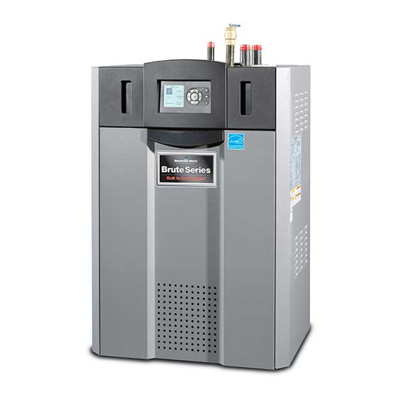
Page 2 RADFORD HITE PRESSURE RELIEF VALVE EXHAUST VENT CONNECTION WATER INLET GAS CONNECTION WATER OUTLET AIR INLET CONNECTION USER CONTROL INTERFACE ON / OFF SWITCH HEAT EXCHANGER DRAIN VALVE GAS VALVE CONDENSATE TRAP VENTURI AIR TRANSITION AIR/ GAS BLOWER Figure 1. -
Page 7: Warranty
Brute Page 3 RUTE. HIGH EFFICIENCY RESIDENTIAL BOILERS 1.4 Warranty Bradford White Brute appliances are covered by a limited warranty. The owner should complete the warranty registration at www.Bradford White.com. All warranty claims must be made to an authorized Bradford White representative. -
Page 8: Dimensions
Page 4 RADFORD HITE 1.6 Dimensions Size 13½ 34 9½ 24 18¼ 46 7½ 19 10¾ 28 11¾ 30 13¾ 35 10¾ 27 15¼ 39 13 33 13½ 34 18¼ 46 6 16 10¾ 28 11¾ 30 14¼ 36 8¾ 22 15¼... -
Page 9: Locating The Appliance
Brute Page 5 RUTE. HIGH EFFICIENCY RESIDENTIAL BOILERS Section 2 - LOCATING THE APPLIANCE 2.1 General Information APPLIANCE SUGGESTED SERVICE ACCESS CLEARANCE SURFACE INCHES The Brute unit is designed for indoor installations only. Left Side The appliance should be located to provide clearances on all Right Side sides for maintenance and inspection. -
Page 10: Venting And Combustion Air
Bradford White equipment. Suppliers local codes. of stainless steel and polypropylene venting that are not listed on these tables are not permitted for use with Bradford White vent category III/ IV products. ALLOWABLE SINGLE WALL STAINLESS STEEL VENT SUPPLIERS AND PART NUMBERS... - Page 11 When taken from the wall, it must be taken from the outdoors or spaces that freely communicate with the out-of-doors by means of the Bradford White horizontal outdoors. When directly communicating with the outdoors, or wall terminal, shown in Table 7.
-
Page 12: Venting
U.S. may use pipe included with the boiler. instructions are not available for the material used, follow the Bradford White recommendations. Failure to use the appropriate vent material, installation The vent pipe must pitch upward, toward the vent terminal, techniques, glues/sealants could lead to vent failure not less than 1/4”... - Page 13 An exhaust vent terminal must be installed. If an exhaust vent terminal is not available with the certified vent system, Bradford White suggests the use of a coupler fitting from the certified vent system into which the vent terminal screen, included with the Brute and shown in the Unpacking section, be installed.
-
Page 14: Locating Vent & Combustion Air Terminals
12” Side Wall Combustion Air Terminal (30cm) below the vent terminal. The Bradford White side wall combustion air terminal, or concentric terminal must be used when the heater takes air Installations in the Commonwealth of from a side wall. (See Table 7.) Contact Bradford White for... - Page 15 Brute Page 11 RUTE. HIGH EFFICIENCY RESIDENTIAL BOILERS U.S. Installations (see note 1) Canadian Installations (see note 2) A= Clearance above grade, veranda, porch, 12 inches (30 cm) 12 inches (30 cm) deck, or balcony See note 6 See note 6 B= Clearance to window or door that may be Direct vent only: 12 inches (30cm);...
- Page 16 Page 12 RADFORD HITE 3.4 Locating Vent and Combustion Air 720 and be ANSI/UL 2034 listed and IAS certified. Terminals (continued) 3. Signage A metal or plastic identification plate shall be permanently mounted to the exterior of the building at a minimum height of eight (8) feet above grade directly in line with the exhaust vent terminal for horizontally vented gas fueled heating appliance or equipment.
-
Page 17: Common Vent Test
Brute Page 13 RUTE. HIGH EFFICIENCY RESIDENTIAL BOILERS Section 4 - steps shall be followed with each appliance remaining connected to the common venting system placed in operation, GAS SUPPLY AND PIPING while the other appliances remaining connected to the common venting system are not in operation. -
Page 18: Pump Requirements
Page 14 RADFORD HITE Section 5 - Brute NATURAL GAS PUMP REQUIREMENTS REQUIRED CU FT TO SIZE PIPING: SIZE / HR. Measure linear distance from meter outlet to last boiler. Add total input of all boilers and divide 5.1 Brute Boiler Flow and Head by 1000 to obtain cu ft / hr required. -
Page 19: System Piping: Hot Supply Connections
Figure the cooling cycle. Brute BNTH models can also be ordered with or without a A boiler installed above radiation level, or as required by the pump included. authority having jurisdiction, must be provided with a low... -
Page 20: Condensate Drain
HITE 6.3 Condensate Drain A condensate drain trap is built into the Brute unit. NOTE: Bradford White supplied pumps are not all Connect a 3/4” PVC pipe between the drain connection and capable of maintaining the reduced temperature rise a floor drain (or a condensate pump if a floor drain is not accessible). - Page 21 Brute Page 17 RUTE. HIGH EFFICIENCY RESIDENTIAL BOILERS Brute Figure 9. - Hydronic Piping — Single Boiler, Zoning with Circulators...
- Page 22 Page 18 RADFORD HITE Brute Figure 10. - Hydronic Piping — Single Boiler, Low Temp Radiant Space Heating Using Low Loss Header and Zone Valves...
- Page 23 Brute Page 19 RUTE. HIGH EFFICIENCY RESIDENTIAL BOILERS Brute Brute Figure 11. - Hydronic Piping — Multiple Boilers, Zoning with Circulators...
- Page 24 Page 20 RADFORD HITE Brute Brute Figure 12. - Hydronic Piping — Multiple Boilers with Indirect DHW Tank Piped from System Loop...
- Page 25 Brute Page 21 RUTE. HIGH EFFICIENCY RESIDENTIAL BOILERS Brute Brute Brute Brute Figure 13. - Hydronic Piping — Multiple Boilers, Reverse Return, Multi-Temp Zones, Zoning with Circulators...
- Page 26 Page 22 RADFORD HITE Figure 14. - Hydronic Piping — Heating Zones with Indirect DHW Tank Piped with Zone Pumps The indirect DHW tank is piped directly off of the boiler. The boiler pump must shut down during DHW operation.
- Page 27 Brute Page 23 RUTE. HIGH EFFICIENCY RESIDENTIAL BOILERS Figure 15. - Hydronic Piping, Multiple Boilers with Indirect DHW Off of One Boiler The boiler pump must shut down during DHW operation.
-
Page 28: Electrical And Wiring Diagrams
Page 24 RADFORD HITE Section 7 - ELECTRICAL AND WIRING DIAGRAMS 7.1 Installation Warnings Connect a 15A fused, 120-volt supply to the main power switch. (The hot leg is connected directly to the switch.) The neutral leg is connected directly to the white wire. The ground wire can be connected to the grounding lug on the control WARNING panel. -
Page 29: Hydronic Heating Using External Mod
The modulation rate is controlled by a 4-20mA signal supplied by an external control. (This can also be 0-10Vdc using a converter - Bradford White part number CA006100.) When setting up a system using an external control, take care to set Anti-Short Cycle feature to prevent “hunting “... -
Page 30: Lead Lag Connections
Page 26 RADFORD HITE 7.6 Lead Lag Connections Lead Boiler Brute boilers can be connected in a lead / lag series up to a total of 8 residential Brutes. One as the Lead control and 7 more as the following controllers. For general info and menu set-up for Lead Lag using your Brute Touchscreen, See page 41 ‘About Lead Lag’. - Page 31 Brute residential boilers can be controlled and monitored Following Boiler using the ‘Gateway’ system, but only if one of the EMEA User Interfaces is replaced with the Bradford White color touchscreen. Call your Bradford White Representative for the touchscreen conversion kit Optional Touchscreen User Interface Kit (KM50D7130) and the Gateway Control (H2354400, Doc# 4236).
-
Page 32: System Wiring Diagram
Page 28 RADFORD HITE 7.8 System Wiring Diagram LTGN OR/GN DISPLAY DISPLAY DISPLAY (Honeywell) (Honeywell) TO J4-10 OPTIONAL SWITCH USED ON SOME VALVE MODELS. IF SWITCH IS NOT INSTALLED IN OR/GN OR/WH COMMON THIS LOCATION. THE PRESSURE GY/GN TERMINAL JUMPER SWITCH LTGN SHOULD BE IN PLACE "HOT"... - Page 33 Page 29 Brute RUTE. HIGH EFFICIENCY RESIDENTIAL BOILERS LTGN OR/GN DISPLAY DISPLAY (Honeywell) (Honeywell) OPTIONAL SWITCH USED ON SOME MODELS. IF SWITCH IS NOT INSTALLED IN THIS LOCATION, THE TERMINAL JUMPER SHOULD BE IN PLACE PRESSURE SWITCH BOILER OR/GN BOILER PUMP PUMP GY/GN INTERRUPT...
-
Page 34: Ladder Diagram
Page 30 RADFORD HITE 7.9 Ladder Diagram Figure 19. - Ladder Diagram... -
Page 35: The User Interface
Brute Page 31 RUTE. HIGH EFFICIENCY RESIDENTIAL BOILERS Section 8 - THE USER INTERFACE 8.2 Navigating the User Interface 8.1 About the User Interface Navigating into the Display area menus is as easy as it The User Interface of the Brute has two main parts: looks. The Info/Install button will be the primary button •... -
Page 36: The Home Display
Page 32 RADFORD HITE 8.3 The Home Display All of your Controls, Diagnostics, Setups, and more, are When the boiler is operating normally, the controller will accessed starting with the Info/Display screen. display the Home display. See Figure • From the Home display shown in Figure 20, press the “I”... - Page 37 Brute Page 33 RUTE. HIGH EFFICIENCY RESIDENTIAL BOILERS Quick Start This menu gives you an easy way to check or change the most common set- tings on the unit: • CH setpoint • DHW setpoint • Outdoor reset • Low water temperature •...
- Page 38 OEM Level Some of the settings can only be changed at • Use the Up- and Down-Arrow buttons to change the value the Bradford White factory. in that box. Once you enter a password, the password access remains • You can change the numbers in the other boxes in the same valid until you exit to the normal no-password state.
-
Page 39: Quick Start Menu
Brute Page 35 RUTE. HIGH EFFICIENCY RESIDENTIAL BOILERS 8.6 Quick Start Turning a Function On and Off Some of the values can be enabled or disabled. See the example below. Figure 25. - Enable/ Disable Screen Figure 28. - Quick Start Menu • Use the Up- and Down-Arrows to highlight the line you want, then press the round OK button. -
Page 40: Configuration And Setup
Page 36 RADFORD HITE Outdoor Reset Functions - Configuration and Setup The next four lines in the display are used to set up the Outdoor Reset functions: 8.7 24 VAC Transformer • Outdoor Reset Enable/Disable - Note: This function with Integral Circuit Breaker can be Enabled/Disabled only by a factory trained 24Vac is supplied by a transformer mounted underneath the technician. -
Page 41: Outdoor Reset
Brute Page 37 RUTE. HIGH EFFICIENCY RESIDENTIAL BOILERS Figure 31. - Control Panel Layout Connect the outdoor air temperature sensor to terminal block 7 In the graph shown above, the sloping line shows the (TB7), using the connections labeled Outdoor Temp Sensor. setpoint which is actually used by the system. Without Outdoor Reset, this would be a constant 130°F (or whatever other value you choose), regardless of the outdoor 8.11... -
Page 42: Warm Weather Shutdown
Page 38 RADFORD HITE Here are instructions for setting up the Outdoor Reset using the Lead/ Lag function – function. Notice that these instructions will be different, How to get there: From the “Home” screen, press “I” to depending on whether you have a single boiler or more than go to “Info/ Install.”... -
Page 43: Domestic Hot Water
Brute Page 39 RUTE. HIGH EFFICIENCY RESIDENTIAL BOILERS 8.13 Domestic Hot Water A Brute unit can be configured to supply domestic hot water be used for both functions.) (DHW) as a stand-alone “volume” unit (DHW models) or as Here are instructions for setting up the Warm Weather a secondary function while the unit also provides hydronic Shutdown function. - Page 44 Page 40 RADFORD HITE de-energizes the System pump and energizes the DHW pump. and water temperatures. The heater setpoint is used to limit the maximum water temperature leaving the boiler only. The The domestic hot water temperature sensor or an aquastat modulation rate is controlled by a 4-20mA signal supplied by is used to monitor the DHW demand.
-
Page 45: About Lead Lag Operation
Brute Page 41 RUTE. HIGH EFFICIENCY RESIDENTIAL BOILERS If your system has just one boiler – priority, the priority will continue during the priority time. How to get there: From the “Home” screen, press “I” to If your system has just one boiler – go to “Info/ Install.”... - Page 46 Page 42 RADFORD HITE 8.14 About Lead Lag Operation (continued) Boiler 1 Boiler 2 Boiler 3 Boiler 4 Display Controller Burner Figure 33. – “Lead Lag” Operation in a System with Four Boilers. Note - the Displays on Boilers 2 thru 4 will display information pertaining only to that specific boiler. Number of boilers Base load value installed NOTE: If your Brutes are Lead Lag configured, you...
- Page 47 Brute Page 43 RUTE. HIGH EFFICIENCY RESIDENTIAL BOILERS Low demand - Low demand - The first boiler in The first boiler in sequence fires at sequence fires at less than 65% less than 65% First Third Fourth First Third boiler boiler boiler boiler...
- Page 48 Page 44 RADFORD HITE 8.14 A bout Lead Lag Operation 8.15 Adjusting CO (continued) high fire. Measure the CO in the flue products at The Brute can be forced to high fire to allow for easier setup. The controller has a feature that makes it easy Control Settings for Lead Lag System - Part 2 to go directly to the high fire condition.
-
Page 49: Adjusting Co 2
Brute Page 45 RUTE. HIGH EFFICIENCY RESIDENTIAL BOILERS The Gas Valve in the 80 thru 210 is at the front of the unit and can be reached after the front panel is pulled forward and then off. Always be patient with your combustion analyzer when making adjustments to the valve at both Hi-Fire and Low-Fire. -
Page 50: First Start-Up And Adjustment Instructions
Do not use this appliance if any part has been under boiler pump on and off 10 times, 10 seconds on and 10 water. Bradford White requires boilers and water seconds off . Then run the system and appliance pumps heaters to be replaced, not repaired, if they have for a minimum of 30 minutes with the gas shut off. -
Page 51: Restarting The Brute Unit
Brute Page 47 RUTE. HIGH EFFICIENCY RESIDENTIAL BOILERS 9.3 Restarting the Brute Unit and turn on the gas and main electrical power (circuit breaker) to the unit. If the unit has been drained, see Section 9.1 in this manual Turn the Brute on at the On/Off switch. for instructions on filling and purging the unit properly. -
Page 52: Maintenance
Component Description instructions in Section 9. Once the boiler is operating. check for leaks again and confirm that all fasteners are tight. Use only genuine Bradford White replacement parts. Check the appliance setup according to Section 9. Caution Label all wires prior to disconnection when servicing Appliance Control controls. - Page 53 Brute Page 49 RUTE. HIGH EFFICIENCY RESIDENTIAL BOILERS factory for proper trouble shooting practices prior to replacing the two wires connected to the assembly. Then remove the the control. If control replacement is required, turn off all two bolts connecting the ignitor assembly to the burner door. power to the appliance and shut off all manual gas valves If the old ignitor assembly is determined to be defective, to the appliance.
- Page 54 Page 50 RADFORD HITE WARNING Transformer with Integral Circuit Breaker Black carbon soot buildup on a dirty heat exchanger The appliance has a 24Vac transformer with integral 4 amp can be ignited by a random spark or flame. To prevent circuit breaker installed to supply the control voltage required this from happening, dampen the soot deposits with for the appliance.
-
Page 55: Gas Conversion
Brute Page 51 RUTE. HIGH EFFICIENCY RESIDENTIAL BOILERS Optional Pressure Gas Switches size (mbtu) Kit number The high and low pressure gas switches are 24V manual reset CA006201 switches that act to cut power to the gas valves if the gas CA006202 pressure is too low or too high for proper operation. CA006203 CA006204 If your boiler is equipped with the Optional pressure gas... -
Page 56: Operating Details And Troubleshooting
Page 52 RADFORD HITE Section 11 - There is a pre-ignition time of two seconds to check the flame sensor operation and status. During this period an OPERATING DETAILS AND intermittent spark can be seen. TROUBLESHOOTING Next there is a trial for ignition period of four seconds. The direct spark ignition switches to constant spark for three seconds. -
Page 57: Anti-Short-Cycle
Brute Page 53 RUTE. HIGH EFFICIENCY RESIDENTIAL BOILERS 11.5 Anti-Short-Cycle (ASC) 11.7 Diagnostics Because the Brute unit is a modulating boiler, and its input Use the Diagnostics to check the status of the sensors and the will decrease when there is a reduction in the heating load, digital inputs and outputs. -
Page 58: Replacement Parts
12.1 General Information To order or purchase parts for the Bradford White Brute, contact your nearest Bradford White dealer or distributor. If they cannot supply you with what you need, contact Customer Service. (See the back cover for the address, telephone and fax numbers.) 12.2 Parts List... - Page 59 Brute Page 55 RUTE. HIGH EFFICIENCY RESIDENTIAL BOILERS SIZE SIZE SIZE SIZE ITEM DESCRIPTION Condensate Trap Assy R20D4020 R20D4020 R20D4020 R20D4020 Heat Exch. Rail Clip R50D1006 R50D1006 — — PVC Reducer — — RP2053000 RP2053000 30a CPVC Reducer RD2010501 RD2010501 RP2065600 RP2065600 or Coupling...
- Page 60 Page 56 RADFORD HITE SIZE SIZE SIZE SIZE ITEM DESCRIPTION Flame Sensor S2112700 S2112700 S2112700 S2112700 74C Flame/Sensor Gasket RW2013400 RW2013400 RW2013400 RW2013400 Air/Gas Channel RS2108400 RS2108600 RS2108600 RS2108700 (80-600) 75A Screw, Air/Gas RS2109400 RS2109400 RS2109400 RS2109400 Channel Drain R10-143 R10-143 R10-143 R10-143...
- Page 61 Brute Page 57 RUTE. HIGH EFFICIENCY RESIDENTIAL BOILERS Optional Touchscreen User Interface Kit (KM50D7130) Call Factory. Figure 40. - Jacket Components...
- Page 62 Page 58 RADFORD HITE Figure 41. - Gas Train Components, Sizes 80-210 S2111000 Figure 42. - Internal Components, Sizes 80–210...
- Page 63 Brute Page 59 RUTE. HIGH EFFICIENCY RESIDENTIAL BOILERS Figure 43. - Heat Exchanger Components...
- Page 64 Page 60 RADFORD HITE Figure 44. - Electrical Components...
-
Page 65: Appendix A - Software Control Functions
Brute Page 61 RUTE. HIGH EFFICIENCY RESIDENTIAL BOILERS Appendix A - SOFTWARE CONTROL FUNCTIONS This table includes a listing of all of the control functions that can be used by the operator or installer. Functions that require a password are indicated in the second column. Name Function How to get there... - Page 66 Info/ Display Setup of the Home display, and to set the brightness of the display. General configuration Used by the Bradford White factory. Info/ Advanced Setup/ System Config./ System Config. I gain (CH) This gain is applied to the Integral term of the PID Info/ Advanced Setup/ CH equation for the CH loop.
- Page 67 Brute Page 63 RUTE. HIGH EFFICIENCY RESIDENTIAL BOILERS Name Function How to get there Max. outdoor temp. (CH) - Used with Outdoor Reset – Quick Start This is the maximum outdoor temperature at which Info/ Advanced Setup/ CH the Outdoor Reset feature will be active. Above Configuration/ Outdoor Reset Config.
- Page 68 Page 64 RADFORD HITE Name Function How to get there Off hysteresis (DHW) When producing Domestic Hot Water – Info/ Advanced Setup/ DHW Configuration The control system will not shut off the boiler until the temperature at the System sensor rises to the DHW setpoint plus a hysteresis value (normally about 10°F).
- Page 69 Brute Page 65 RUTE. HIGH EFFICIENCY RESIDENTIAL BOILERS Name Function How to get there Pump exercise interval The system can be set to exercise the pumps at Info/ Advanced Setup/ System set intervals. Enter a non-zero value to turn on the Config./ Pump Config.
-
Page 70: Appendix B - Error Messages
Page 66 RADFORD HITE Appendix B - ERROR MESSAGES This table includes a listing of the faults that might be generated by the controller, and displayed on the Operator Interface. Some of these can be corrected by an installer changing a parameter, while other conditions are more complicated, and will require a service technician. - Page 71 Brute Page 67 RUTE. HIGH EFFICIENCY RESIDENTIAL BOILERS Internal fault: Safety relay test failed due to safety relay not OFF Internal fault Internal fault: 1. Reset module Safety relay test failed due to feedback 2. If fault repeats, replace module. not ON Internal fault: Safety RAM write...
- Page 72 Page 68 RADFORD HITE AC input phases reversed 1. Check the module and display connections. 2. Check the module power supply and make sure that both frequency and voltage meet the specifications. 3. On 24 VAC applications, assure that J4 terminal 10 and J8 terminal 2 are connected together.
- Page 73 Brute Page 69 RUTE. HIGH EFFICIENCY RESIDENTIAL BOILERS DHW (Domestic Hot Water) high limit H or L 1. Check wiring and correct any possible errors. 2. Replace the DHW high limit. 3. If previous steps are correct and fault persists, replace the module.
- Page 74 Page 70 RADFORD HITE Flame detected out of sequence H or L 1. Check that flame is not present in the combustion chamber. Correct any errors. 2. Make sure that the flame detector is wired to the correct terminal. 3. Make sure the F & G wires are protected from stray noise pickup.
- Page 75 Brute Page 71 RUTE. HIGH EFFICIENCY RESIDENTIAL BOILERS Combustion pressure and flame On H or L 1. Check that flame is not present in the combustion chamber. Correct any errors. 2. Make sure that the flame detector is wired to the correct terminal. 3.
- Page 76 Page 72 RADFORD HITE Invalid Blower/ HSI output setting Invalid Delta T limit enable setting Invalid Delta T limit response setting Invalid DHW (Domestic Hot Water) high limit enable setting Invalid DHW (Domestic Hot Water) high limit response setting 1. Recheck selected parameters, reverify and reset module. Invalid flame sensor type setting 2.
- Page 77 Brute Page 73 RUTE. HIGH EFFICIENCY RESIDENTIAL BOILERS Invalid Outlet high limit response setting Invalid PII (Pre-Ignition Interlock) enable setting Invalid Postpurge time setting Invalid Power up with lockout setting 1. Recheck selected parameters, reverify and reset module. Invalid Preignition time setting 2.
- Page 78 Page 74 RADFORD HITE Notes:...
- Page 79 Brute Page 75 RUTE. HIGH EFFICIENCY RESIDENTIAL BOILERS Notes:...
- Page 80 Residential Boilers Notes: Dimensions and specifications subject to change without notice in accordance with our policy of continuous product improvement. 200 Lafayette St. www.BradfordWhite.com Middleville, MI 49333 Warranty: (800) 531-2111 Litho in U.S.A. © Bradford White 1610 Document 1258F...
Need help?
Do you have a question about the Brute BNTH and is the answer not in the manual?
Questions and answers