Table of Contents
Advertisement
Quick Links
Installation and Operation Instructions
These instructions are to be stored next to the boiler for reference purposes.
FOR YOUR SAFETY: This product must be installed and serviced by a professional service technician,
qualified in hot water boiler installation and maintenance. Improper installation and/or operation could
create carbon monoxide gas in flue gases which could cause serious injury, property damage, or death.
Improper installation and/or operation will void the warranty.
If the information in this manual is not followed
exactly, a fire or explosion may result causing
property damage, personal injury or loss of life.
Do not store or use gasoline or other flammable
vapors and liquids in the vicinity of this or any
other appliance.
WHAT TO DO IF YOU SMELL GAS
• Do not try to light any appliance.
• Do not touch any electrical switch; do not use
any phone in your building.
• Immediately call your gas supplier from a
nearby phone. Follow the gas supplier's
instructions.
• If you cannot reach your gas supplier, call the
fire department.
Installation and service must be performed by
a qualified installer, service agency, or gas
supplier.
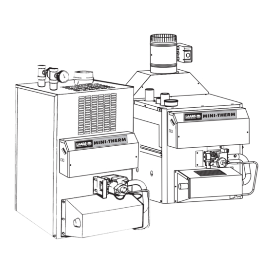
JVH
WARNING
Installation and
Operation Instructions for
M
INI
Residential
Gas-Fired
Hydronic Boilers
Models JVH, JVS
Sizes 50-225
JVS
U.S. Patent No. 1,609,692
Canada Patent No. 383,318
Vent damper is optional in some provinces of Canada..
Assurez-vous de bien suivres les instructions
données dans cette notice pour réduire au
minimum le risque d'incendie ou d'explosion
ou pour éviter tout dommage matériel, toute
blessure ou la mort.
Ne pas entreposer ni utiliser d'essence ni
d'autres vapeurs ou liquides inflammables dans
le voisinage de cet appareil ou de tout autre
appareil.
QUE FAIRE SI VOUS SENTEZ UNE ODEUR DE GAZ:
• Ne pas tenter d'allumer d'appareils.
• Ne touchez à aucun interrupteur. Ne pas
vous servir des téléphones dansle bâtiment
où vous êtes.
• Appelez immédiatement votre fournisseur de
gaz depuis un voisin. Suivez les instructions
du fournisseur.
• Si vous ne pouvez rejoindre le fournisseur
de gaz, appelez le sservice des incendies.
L'installation et l'entretien doivent être assurés
par un installateur ou un service d'entretien
qualifié ou par le fournisseur de gaz.
Document 1254D
-T
HERM
AVERTISSEMENT
Advertisement
Table of Contents

Related Manuals for Bradford White Laars MINI-THERM JVH


Summary of Contents for Bradford White Laars MINI-THERM JVH
- Page 1 Installation and Operation Instructions Document 1254D Installation and Operation Instructions for HERM Residential Gas-Fired Hydronic Boilers Models JVH, JVS Sizes 50-225 U.S. Patent No. 1,609,692 Canada Patent No. 383,318 Vent damper is optional in some provinces of Canada.. These instructions are to be stored next to the boiler for reference purposes. FOR YOUR SAFETY: This product must be installed and serviced by a professional service technician, qualified in hot water boiler installation and maintenance.
-
Page 2: Table Of Contents
Page 2 LAARS Heating Systems TABLE OF CONTENTS SECTION 1. SECTION 6. Electrical Wiring ...........21 General Information Introduction ............3 Outdoor Reset ..........21 Warranty ............3 Wiring Diagrams ........22-25 Model Number and Nomenclature ....4 SECTION 7. Filling the System ........26 SECTION 2. Boiler Assembly &... -
Page 3: General Information
Page 3 HERM SECTION 1. General Information 1A. Introduction 1B. Warranty This manual provides information necessary for The Laars Mini-Therm model JV boilers are covered the installation, operation, and maintenance of the by a limited warranty. The owner should complete the warranty registration online by going to www.Laars. -
Page 4: Model Number And Nomenclature
Page 4 LAARS Heating Systems 1C. Model Number and Nomenclature The rating plate on the side of your Mini-Therm shows your Model Number. The original characteristics of your unit can be identified using this nomenclature from your Model Number. MODEL IGNIT SIZE FUEL... -
Page 5: Boiler Placement
Page 5 HERM Vent Damper (JVS only): 2C. Flooring Mini-Therm JVS boilers have built-in draft diverter for natural draft operation. JVS model boilers can only be installed on Find the vent damper box which is located in the noncombustible flooring. boiler package. -
Page 6: Dimensional Information
Page 6 LAARS Heating Systems 2D. JVH Dimensional Information inches Dimensions in Water Size Connection Connection 1-1/4 13-3/8 3-1/8 2-7/8 1-1/4 13-3/8 2-1/4 1-1/4 16-7/8 5-3/4 2-7/8 1-1/4 16-7/8 5-1/2 1-1/4 20-3/8 7-1/4 1-1/4 25-5/8 JVH Dimensions 9 -1/4... - Page 7 Page 7 HERM 2D. JVS Dimensional Information inches Dimensions in 9 -1/4 Water Conn Conn Size 1-1/4 13-3/8 340 27-3/4 23-5/8 21-3/4 550 26-1/2 1-1/4 13-3/8 340 27-3/4 24-1/8 21-3/4 550 27-1/2 1-1/4 16-7/8 430 28-3/4 24-1/8 22-3/4 580 27-1/2 1-1/4 16-7/8 430 28-3/4...
-
Page 8: Clearance / Closet Installations
Page 8 LAARS Heating Systems width and depth of the heater by at least 12 inches Special attention should be paid to clearances (305mm) in all directions. The masonry must be laid between the front of the boiler and the closet door with ends unsealed, and joints matched to provide free circulation of air from side to side through the when it is closed. -
Page 9: Air And Venting
Page 9 HERM SECTION 3. Boiler Size Outside Air Area Inside Air Area Air and Venting sq. in sq. in. sq. cm sq. cm 3A. Combustion Air Supply The boiler location must provide sufficient air supply for proper combustion, and ventilation of 1032 the surrounding area as outlined in the latest edition 1452... -
Page 10: Venting
Page 10 LAARS Heating Systems 10 (3.0) OR LESS MORE THAN 10 (3.0) 2 (0.6) MIN. 3 (0.9) 3 (0.9) MIN. MIN. WALL OR WALL OR PARAPET TERMINATION PARAPET CHIMNEY 10 FT. (3.0m) CHIMNEY OR LESS FROM RIDGE, NOTE: NO HEIGHT WALL OR PARAPET 10 (3.0) ABOVE PARAPET... -
Page 11: Vertical Venting - Category I
Page 11 HERM Avoid terminating boiler vents near air conditioning WARNING or air supply fans. The fans can pick up exhaust Do not store any chemical, cleaners, or other flue products from the boiler and return them to the building, creating a possible health hazard. corrosive material near combustion air openings or in the room. -
Page 12: Horizontal Venting - Category Iii
Page 12 LAARS Heating Systems national and local codes must be followed! The use the manufacturers of products that comply with the of thimbles, firestops and other protective devices, requirements of UL 1738 / ULC-S636 and the part when penetrating combustible or noncombustible numbers of component parts. -
Page 13: Vent Terminations
SS to PP 2ZDCPVCx** FSAAUx-xPP *4", 6" & 7" only **up to 6" Page 13 HERM Horizontal Run Length No. of Diameter Common Venting System Size Elbows 50 - 160 10.7 When an existing boiler is removed from a common venting system, the common venting system is likely 10.7 to be too large for proper venting of the appliances... -
Page 14: Gas Connections
Page 14 LAARS Heating Systems SECTION 4. Caution Permanent damage to the gas valve will occur Gas Connections if the following procedures are not followed. 4A Gas Supply and Piping Attention Vous endommagerez la soupape de gaz Gas piping installation must be in accordance si vous ne respectez pas les procédures with the latest edition of ANSI Z223.1 and all suivantes. -
Page 15: Special Precautions For Lp
Page 15 HERM WARNING The Mini-Therm JVS and JVH boilers are Caution designed for use with either natural gas or LP Some leak test solutions (including soap and gas. Check the rating plate to be sure that the water) may cause corrosion or stress cracking. Rinse the piping with water after testing. -
Page 16: By-Pass Piping
Page 16 LAARS Heating Systems dedicated to pumping the boiler only. This circulator the two drain plugs located on the lower left side of should be sized for the boiler head loss and flow rate. the boiler. Be sure to include air vent devices located at the highest point in the system to eliminate trapped air, All precautions must be taken by the installer to insure that a maximum temperature rise through the boiler... - Page 17 Page 17 HERM Multi-Zone Single Circuit System Valve System Primary Multi-Zone Secondary Pump Multi-Zone System Pump System Primary/Secondary Multi-Zone Valve System Primary/Secondary Multi-Zone Valve System Low Temperature Installation KEY: PUMP CHECK VALVE VALVE ZONE VALVE UNION AUTO AIR BLEEDER Figure 10. Typical Plumbing Installations.
-
Page 18: Flow Requirements
Page 18 LAARS Heating Systems piping, one zone valve and up to eight elbows for single zone systems. Consult the factory or a qualified System system designer if you have more fittings or different From size or type of pipe. System Balancing Valve... -
Page 19: Low Water Cut Off (Lwco)
Page 19 HERM 5 I Low Water Cut Off (LWCO) When this boiler is installed above radiation level, it is required that a Low Water Cut-Off (LWCO) be installed unless this requirement is superceded by Jurisdictional requirements. Specific instructions for the installation are the following: Locate the appropriate wiring diagram within this manual. -
Page 20: Typical Plumbing Diagrams
Page 20 LAARS Heating Systems 5 J Typical Plumbing Diagrams The preferred piping configuration for JV boilers is always using primary/secondary piping. There are some applications that are acceptable without primary/secondary piping, see below. LOW TEMP SYSTEMS Tempering Isolation Valve Pump Isolation Valve... -
Page 21: Electrical Wiring
Page 21 HERM SECTION 6. WARNING The boiler must be electrically grounded in 6A. Electrical Wiring accordance with the requirements of the authority having jurisdiction or, in the absence of such Follow these instructions to make the necessary requirements, with the latest edition of the national initial electrical connections. -
Page 22: Wiring Diagrams
Page 22 LAARS Heating Systems 6C Wiring Diagrams... - Page 23 Page 23 HERM...
- Page 24 Page 24 LAARS Heating Systems 110 VAC 110 VAC TEMP CONTROL CONTROL TEMP BOILER PUMP CONTROL PUMP 5A MAX CONTROL INDUCER TRANSFORMER TRANSFORMER 110V FUSE TEMP CONTROL TEMP CONTROL FUSE TEMP GAS VALVE DAMPER CONTROL HI LIMIT TEMP CONTROL BLOCKED ROLLOUT ROLLOUT POWER VENTER...
- Page 25 Page 25 HERM HEAT Wiring with Taco Zone Valves HEAT Wiring with Honeywell Zone Valves HEAT Wiring with Multiple Zone Pumps Figure 17. Multiple Zone Wiring.
-
Page 26: Filling The System
Page 26 LAARS Heating Systems SECTION 7. 7A Filling the System It is crucial to the efficient operation of the system that all air be removed from the circuit. For this reason, an air scoop and vent should be located close to the boiler outlet, and there should be a minimum distance between cold water feed and system purge valve. -
Page 27: Operating Procedures
Page 27 HERM SECTION 8. Operating Procedures Before placing the boiler in operation, check and reset the safety shutoff devices. Once the boiler is connected to the gas and water piping and after all the requirements in previous pages have been met, follow these procedures: 8A. -
Page 28: Operating Instructions, Jvh
Page 28 LAARS Heating Systems 8C. Operating Instructions Mini-Therm JVH... -
Page 29: Operating Instructions, Jvs
Page 29 HERM 8D. Operating Instructions Mini-Therm JVS... -
Page 30: Operating Temperature Control
Page 30 LAARS Heating Systems Off there is no post purge of the pump, the pump turns off immediately after the last call is removed. Laars strongly recommends using a pump post purge. During Control Access WWSD and a call for HEAT is present the pump will Panel remain off. - Page 31 Page 31 HERM DHW Operation The boiler target for DHW calls Summary of Dip Switch Settings: #1 Two Stage (Off) / Single Stage (On) is fixed at 180 deg F. Note: There is no control of a DHW pump, so the (Note: Efficiency may be reduced with 2-stage boiler pump runs with the call for DHW.
-
Page 32: Maintenance
Page 32 LAARS Heating Systems 10. The gas and electric controls on the boiler SECTION 9. are engineered for long life and dependable 9A. Maintenance operation, but the safety of the equipment Lubricate the water circulating pump per the depends on their proper functioning. It is strongly instructions on the pump. -
Page 33: Electrical Troubleshooting
Page 33 HERM 9B. Electrical Troubleshooting Caution Remove the control box cover on the front of the Label all wires prior to disconnection when boiler. servicing controls. Wiring errors can cause Verify that 115 volts is reaching the boiler by improper and dangerous operation. - Page 34 Page 34 LAARS Heating Systems Symptom Cause Remedy Pump not operating No power ..Check circuit breakers and power source. Replace. Recheck Pump defective ..wiring diagrams. Incorrectly wired ..Pilot outage Inlet gas pressure too low .
- Page 35 Page 35 HERM Troubleshooting Honeywell SV9501/SV9601 Hot Surface Pilot System (JVH only) START • TURN GAS SUPPLY OFF CHECK: • LINE VOLTAGE POWER • SET THERMOSTAT TO CALL FOR HEAT • LOW VOLTAGE TRANSFORMER • LIMIT CONTROLLER SV9501/SV9601 IS • THERMOSTAT POWERED •...
-
Page 36: Glossary Of Terms
Page 36 LAARS Heating Systems SECTION 10. Replacement Parts 10A Glossary of Terms Air Vent Primary-Secondary Piping Two or more interconnecting circulating loops, A device used to purge air from the Circuit. Should be located at the highest point in the Circuit. each with its own pump. -
Page 37: Parts List Jvh
Page 37 Page 37 HERM HERM 10B Parts List JVH 10B Parts List JVH Mini-Therm JVH Size Description JVH-50 JVH-75 JVH-100 JVH-125 JVH-160 JVH-225 Gas System 1 Pilots Pilot Assembly (Nat.), Hot Surface RW2001800 RW2001800 RW2001800 RW2001800 RW2001800 RW2001800 Pilot Assembly (LP), Hot Surface RW2001900 RW2001900 RW2001900... - Page 38 Page 31 Page 38 LAARS Heating Systems (left side) (right side) ITEMS 14, 39 Figure 19A. JVH Parts Identification. AND INSULA TION NOT SHOWN...
-
Page 39: Parts List Jvs
Page 39 HERM Page 39 HERM 10C Parts List JVS 10C Parts List JVS Mini-Therm JVS Size Description JVS-50 JVS-75 JVS-100 JVS-125 JVS-160 JVS-225 Gas System 1 Pilots Pilot Assembly (Nat.) R0061600 R0061600 R0061600 R0061600 R0061600 R0061600 Pilot Assembly (LP) W0039600 W0039600 W0039600... - Page 40 LAARS Heating Systems Mini-Therm JVS (on left side) All Manuals (Install & Operate, Start Up, and Service Manuals) can be downloaded at www.laars.com For LAARS Product and Service VIDEOS Figure 19B. JVS Parts Identification. h t t p s : / / w w w. y o u t u b e . com/user/LaarsHeating 800.900.9276 •...