Table of Contents
Advertisement
Quick Links
User's Manual
FOR YOUR SAFETY: This product must be installed and serviced by a professional service technician,
qualified in hot water boiler installation and maintenance. Improper installation and/or operation could
create carbon monoxide gas in flue gases which could cause serious injury, property damage, or death.
Improper installation and/or operation will void the warranty. For indoor installations, as an additional
measure of safety, Laars strongly recommends installation of suitable Carbon Monoxide detectors in the
vicinity of this appliance and in any adjacent occupied spaces.
If the information in this manual is not
followed exactly, a fire or explosion may
result causing property damage, personal
injury or loss of life.
Do not store or use gasoline or other
flammable vapors and liquids in the vicinity
of this or any other appliance.
WHAT TO DO IF YOU SMELL GAS
• Do not try to light any appliance.
• Do not touch any electrical switch; do not
use any phone in your building.
• Immediately call your gas supplier from a
nearby phone. Follow the gas supplier's
instructions.
• If you cannot reach your gas supplier, call
the fire department.
Installation and service must be performed
by a qualified installer, service agency, or gas
supplier.
WARNING
User's Manual
for
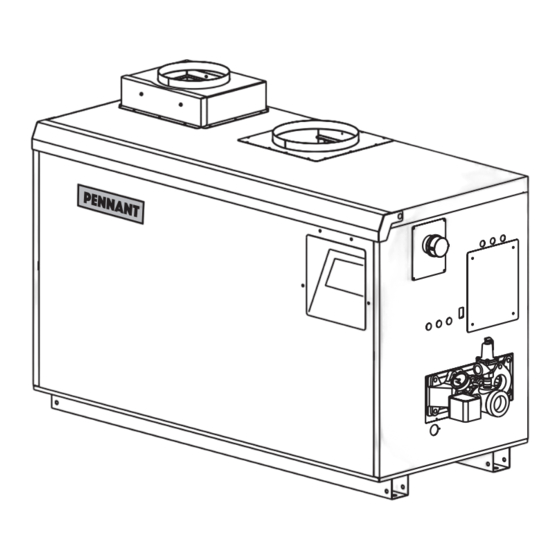
PENNANT
includes
LOW TEMP PENNANT
with Laars Linc™
Hydronic Boiler
Model PNCH
Water Heater
Model PNCV
Sizes 500-2000
U.S. Reg. 2,765,423
AVERTISSEMENT
Assurez-vous de bien suivres les instructions
données dans cette notice pour réduire au
minimum le risque d'incendie ou d'explosion
ou pour éviter tout dommage matériel, toute
blessure ou la mort.
Ne pas entreposer ni utiliser d'essence ni
d'autres vapeurs ou liquides inflammables dans
le voisinage de cet appareil ou de tout autre
appareil.
QUE FAIRE SI VOUS SENTEZ UNE ODEUR DE GAZ:
• Ne pas tenter d'allumer d'appareils.
• Ne touchez à aucun interrupteur. Ne pas vous
servir des téléphones dansle bâtiment où vous
vous trouvez.
• Appelez immédiatement votre fournisseur de
gaz depuis un voisin. Suivez les instructions du
fournisseur.
• Si vous ne pouvez rejoindre le fournisseur de
gaz, appelez le sservice des incendies.
L'installation et l'entretien doivent être assurés par
un installateur ou un service d'entretien qualifié ou
par le fournisseur de gaz.
Document 1374A
®
®
Advertisement
Table of Contents

Related Manuals for Bradford White Laars Pennant PNCH Series


Summary of Contents for Bradford White Laars Pennant PNCH Series
- Page 1 User's Manual Document 1374A User's Manual PENNANT ® includes LOW TEMP PENNANT ® with Laars Linc™ Hydronic Boiler Model PNCH Water Heater Model PNCV Sizes 500-2000 U.S. Reg. 2,765,423 FOR YOUR SAFETY: This product must be installed and serviced by a professional service technician, qualified in hot water boiler installation and maintenance.
-
Page 2: Table Of Contents
Page 2 LAARS Heating Systems TABLE OF CONTENTS SECTION 3 Electrical Connections ......11 SECTION 1 Caring For Your Pennant ....... 3 Installation Warnings .......11 General Care ..........3 Line Voltage Connections ......11 Annual Inspection of Flue and Vents ..3 3.B.1 Main Power..........11 In the Event of a Power Failure .... -
Page 3: Section 1 Caring For Your Pennant
Page 3 Pennant 500-2000), User's Manual SECTION 1 Caring For Your Pennant WARNING Do not use this boiler if any part has been Your Pennant will require very little under water. Immediately call a qualified Maintenance. However, as with any fine appliance service technician to inspect the boiler and to there are certain steps that should be taken to ensure replace any part of the control system and any... -
Page 4: Section 2 Touchscreen And System Ops
Page 4 LAARS Heating Systems SECTION 2 Touchscreen and System Operations 2.A The Home Screen Figure 1. The Home Screen Model Stages Section 6.9 Status Window Low Temp On/Off 500 - 750 1000 2.A.1 Home Screen Status Window 1250 - 2000 Icon Description Setpoint... -
Page 5: Home Screen Active Icons
Page 5 Pennant 500-2000), User's Manual 2.A.2 Home Screen Active Icons Name Icon Description Security Displays the current lock status. Touch the lock icon to lock or unlock the Touchscreen Display. Quick Start Provides quick touch access to the most commonly used parameters for easy installation. -
Page 6: B Lock/Unlock Display Screen
Page 6 LAARS Heating Systems 2.B Lock / Unlock Display Screen Password Protection: To change parameters, a password is required. Logout. Allows the user to log out of the The control system includes three levels of password password. protection. -OEM Password: Setup and parameter changes available only to the factory. -
Page 7: C Keypad Operations
Page 7 Pennant 500-2000), User's Manual 2.C Keypad Operations As you navigate in, you will find that all screens have either a numeric keypad to enter in your customizable parameters OR selection buttons to choose the device of your configuration. NOTE: You can always tell exactly where you have navigated to by Navigation Bar. -
Page 8: D Quick Start
Page 8 LAARS Heating Systems 2.D Quick Start To navigate to the Quick Start Screen, touch the Touching CH1/DHW1 navigates to the CH1/ Quick Start Icon in the lower left-hand portion of the DHW1 Quick Start Screen Home Screen. 2.D.1.a CH1 /DHW1 Screen 4. -
Page 9: Dhw/Dhw3
Page 9 Pennant 500-2000), User's Manual 2.D.2 DHW/DHW3 temperature at which the Pennant will maximize the To navigate to the DHW/DHW3 Quick Start boiler outlet temperature to the Maximum Water Screen, touch the DHW faucet icon on the Quick Start Temperature. -
Page 10: Anti-Short Cycle
Page 10 LAARS Heating Systems 2.D.5 Anti-Short Cycle 2.D.6 Time & Date To navigate to the Anti-Short Cycle Quick Start To navigate to the Time & Date Quick Start Screen, touch the Anti-Short Cycle Icon on the Quick Screen, touch the Time & Date Icon on the Quick Start Start Screen. -
Page 11: Section 3 Electrical Connections
Page 11 Pennant 500-2000), User's Manual SECTION 3 Electrical Connections 3.B.2 Pump Power The pump circuit is identified by three 12 AWG 3.A Installation Warnings wires: black with a white stripe (L2), white (N2), and WARNING green (Ground). This appliance must be electrically grounded in accordance with the requirements of the authority If desired, an installer can change the pump having jurisdiction or, in the absence of such... -
Page 12: Low Voltage Connections
Page 12 LAARS Heating Systems terminals 7 and 8 of the input terminal strip. DHW/DHW3: Connect the aquastat or end switch (isolated contact only) wires to terminals 5 and 6 of the input terminal strip. If preferred, a DHW tank sensor can be used in lieu of an aquastat to generate a heat demand, refer the Installation Manual (Doc 1373) NOTE: The heat demand contacts must be dry... -
Page 13: Field Wiring - Outputs
Page 13 Pennant 500-2000), User's Manual Detail Figure 4. Input and Output Terminal Strips 3.C.2 Field Wiring - Outputs 3.C.2.a Dry Contacts terminal strip. When connected, the Pennant will use Run: These contacts, when used, are connected to this sensor to perform the DHW thermostat function. terminals 1 (common), 2 (normally closed), and 3 The controller automatically detects the presence (normally open) of the output terminal strip. -
Page 14: Cascade Rs485
Page 14 LAARS Heating Systems JUMPER 4 - 20mA NO JUMPER 0 - 10VDC JUMPERS JUMPERS INPUTS OUTPUTS 0 - 10VDC 4-20 mA Figure 5. Analog Input and Output Jumper Placement 3.C.2.b Cascade RS485 A system supply sensor must be installed and connected to the lead boiler, see System Supply in Prior to wiring Pennant units for cascade operations, Section 5.3.1.4 –... -
Page 15: Cascade Wiring Connections
Page 15 Pennant 500-2000), User's Manual 3.D Cascade Wiring Connections Figure 6. Cascade Wiring Connections Figure 7. Cascade BAS Wiring Connections For the complete list of wiring diagrams and logic diagrams, please see the Installation and Operating Manual. Document 1373 SECTION 4 Burner Set Up power to appliance. -
Page 16: ( >2500 Feet )
Page 16 LAARS Heating Systems 6. With the unit running, verify the supply gas pressure, manifold gas pressure, and CO according to the table below. The required instruments used to assist in these Natural Gas Propane adjust-ments are a CO or O Analyzer and a U-Tube Typical...
Need help?
Do you have a question about the Laars Pennant PNCH Series and is the answer not in the manual?
Questions and answers