Table of Contents
Advertisement
Quick Links
Installation and Operation Instructions
FOR YOUR SAFETY: This product must be installed and serviced by a professional service technician,
qualified in hot water boiler and heater installation and maintenance. Improper installation and/or operation
could create carbon monoxide gas in flue gases which could cause serious injury, property damage, or
death. Improper installation and/or operation will void the warranty.
WARNING
If the information in this manual is not
followed exactly, a fire or explosion may
result causing property damage, personal
injury or loss of life.
Do not store or use gasoline or other
flammable vapors and liquids in the vicinity of
this or any other appliance.
WHAT TO DO IF YOU SMELL GAS
• Do not try to light any appliance.
• Do not touch any electrical switch; do not
use any phone in your building.
• Immediately call your gas supplier from a
nearby phone. Follow the gas supplier's
instructions.
• If you cannot reach your gas supplier, call
the fire department.
Installation and service must be performed
by a qualified installer, service agency, or gas
supplier.
Installation and Operation
Instructions for
Brute LX
®
Wall-Mounted Modulating Boiler
Model BLXH
50, 75, 100, 125, 150, 175 & 220 MBH
Combination
Boiler and Water Heater
Model BLXC
Assurez-vous de bien suivres les instructions
données dans cette notice pour réduire au
minimum le risque d'incendie ou d'explosion
ou pour éviter tout dommage matériel, toute
blessure ou la mort.
Ne pas entreposer ni utiliser d'essence ou ni
d'autres vapeurs ou liquides inflammables dans
le à proximité de cet appareil ou de tout autre
appareil.
QUE FAIRE SI VOUS SENTEZ UNE ODEUR DE
• Ne pas tenter d'allumer d'appareils.
• Ne touchez à aucun interrupteur. Ne pas vous servir
des téléphones dans le bâtiment où vous vous
trovez.
• Appelez immédiatement votre fournisseur de
gaz depuis un voisin. Suivez les instructions
du fournisseur.
• Si vous ne pouvez rejoindre le fournisseur de
gaz, appelez le sservice des incendies.
L'installation et l'entretien doivent être assurés par
un installateur ou un service d'entretien qualifié
ou par le fournisseur de gaz.
Document 1295C
125, 150 and 175 MBH
AVERTISSEMENT
GAZ:
Advertisement
Table of Contents

Subscribe to Our Youtube Channel
Related Manuals for Bradford White Brute LX


Summary of Contents for Bradford White Brute LX
- Page 1 Installation and Operation Instructions Document 1295C Installation and Operation Instructions for Brute LX ® Wall-Mounted Modulating Boiler Model BLXH 50, 75, 100, 125, 150, 175 & 220 MBH Combination Boiler and Water Heater Model BLXC 125, 150 and 175 MBH FOR YOUR SAFETY: This product must be installed and serviced by a professional service technician, qualified in hot water boiler and heater installation and maintenance.
-
Page 2: Table Of Contents
Model Nomenclature........... 1 Pump Capacity Brute LX Overview ..........2 Start Up / Shut Down Instruction (Decal) .... 3 5.1 Brute LX Heating System Pump Capacity ..... 19 Dimensions for all Sizes ........4 Unpacking ............6 SECTION 6. Condensate Trap ..........6 Water Connections 1.10... - Page 3 Filling the Boiler System ........41 10.2 Starting the Burner after Set Up ....... 41 10.2.1 Burner Operation ..........41 10.2.2 Boiler Setup and Adjustment ......42 10.3 Shutting Down the Brute LX ......42 10.4 To Restart the Brute LX ........42...
-
Page 4: General Information
This is true for all sizes. WARNING The Brute LX must be installed in accordance with the procedures detailed in this manual, or the Bradford White warranty will be voided. The installation must conform to the requirements of the local jurisdiction having authority, and, in the United States, to the latest edition of the National Fuel Gas Code, ANSI Z223.1/NFPA54. -
Page 5: Introduction
H = Modulating Boiler To remove these panels for further access into the C = Combination Boiler and Water Heater Brute LX, there are two screws that hold each panel in Configuration place. Remove the 2 screws on the upper panel and slide W = Wall Hung the upper metal panel up and out. -
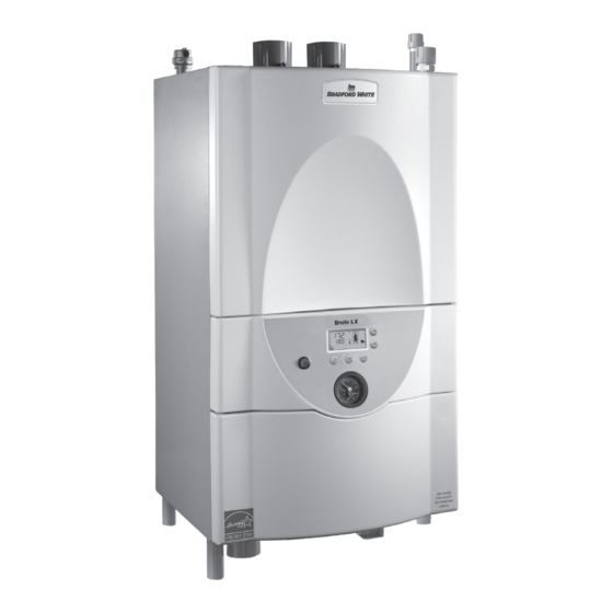
Page 6: Brute Lx Overview
Page 2 BRADFORD WHITE CORP . 1.5 Brute LX, Overview GAS SUPPLY CENTRAL HEAT OUT CONNECTION (SUPPLY WATER) CENTRAL HEAT IN CONNECTION (RETURN WATER) BOTTOM VIEW 2 SCREWS USER INTERFACE ON / OFF SWITCH HOT OUT COLD IN TEMPERATURE /... -
Page 7: Start Up / Shut Down Instruction (Decal)
Page 3 Brute LX 1.6 Start Up / Shut Down Instructions (Decal) The Start Up / Shut Down Instruction (Decal) can be found on the metal panel behind the Top Panel. See Figure This Decal is also referred to as the Operating Instructions Label and/or Warning Label. -
Page 8: Dimensions For All Sizes
Page 4 BRADFORD WHITE CORP . 1.7 Dimensions, Brute LX 17" " HYDRONIC OUTLET " Gas and Hydronic fittings at both the top ELIMINATION and the bottom of the unit. VENT INLET " Exhaust Vent and Air Inlet Collars fit... - Page 9 Page 5 Brute LX Dimension Model 50, 75 MBH 1" (3) 15-3/4" (40) 3-3/4" (9) 9-1/4" (24) 8" (20) 1-1/2" (4) 5-3/4" (14) 15-1/2" (39) 100 MBH 1" (3) 15-1/2" (39) 1-1/4" (3) 12-3/4" (33) 11" (28) 1-1/4" (3) 9-1/2" (24) 14-3/4"...
-
Page 10: Unpacking
Page 6 BRADFORD WHITE CORP . 1.8 Unpacking and the Installation Kit All Brute LX's are shipped in a single box with an Installation Kit. See Figure 5. Unpack the unit and check that all components shown are included with your unit. The Installation Kit contains the following items. -
Page 11: Locating The Appliance
75°F Rise inche 50,000 47,500 95% 1/2” N 14.6 13.2 The Brute LX must be mounted to a suitable wall by a 75,000 71,250 95% 1/2” N 21.9 20.8 qualified heating contractor under the guidelines of a 100 100,000 29.3 95,000 95% 1/2”... -
Page 12: Wall Mount Hole Locations
Bolts/Anchors (4) 8.1 cm Centered provided by installer, Dimensions shown in Inches and centimeters Wall Bracket each is to be suitable for Desired top of Brute LX (supplied) 160 lbs [73kg] Bracket factory- 12P3013 minimum. mounted on back of Brute 16”... -
Page 13: Venting And Combustion Air
Bradford White equipment. Suppliers adhesive to join CPVC and/or PVC pipe and fittings. of stainless steel and polypropylene venting that are not listed on these tables are not permitted for use with Bradford White vent category III/ IV products. Do not mix venting suppliers and models in venting systems. -
Page 14: Combustion Air
(1100 square mm/kW) of total input rating of all A Brute LX unit can take combustion air from the equipment in the enclosure. space in which it is installed, or the combustion air Method 2: One permanent opening, commencing can be ducted directly to the unit. -
Page 15: Ducted Combustion Air
CPVC absence of such requirements, follow CAN/CGA B149. material is recommended. The Brute LX is a Category IV appliance and may 3.2.2 Ducted Combustion Air be installed with PVC, CPVC or polypropylene that The combustion air can be taken through the wall, or complies with ULC-S636, ANSI/ASTM D1785 F441 through the roof. - Page 16 Vent pipe must pitch upward, toward the vent terminal, not less than 1/4" per foot, so that condensate will run back to the Brute LX to drain. Route vent pipe NOTICE to the heater as directly as possible. Seal all joints and...
-
Page 17: About Common Venting
NOTICE Notes: DO NOT COMMON VENT BRUTE LX UNITS.Brute "x", "xx" and "xxxx" refer to variations in nominal size. See manufacturer's LX units are never permitted to share a vent with catalog for a particular application. Category I appliances. -
Page 18: Locating Vent & Combustion Vent Terminals
Locate the vent terminal so that it cannot be 3.4.2 Side Wall Combustion Air Terminal blocked by snow. The installer may determine The Bradford White side wall combustion air terminal, that a vent terminal must be higher than the or concentric terminal... - Page 19 Page 15 Brute LX U.S. Installations (see note 1) Canadian Installations (see note 2) A= Clearance above grade, veranda, porch, 12 inches (30 cm) 12 inches (30 cm) deck, or balcony See note 6 See note 6 B= Clearance to window or door that may be Direct vent only: 12 inches (30cm);...
-
Page 20: Vertical Vent Terminal
Page 16 BRADFORD WHITE CORP . adjacent floor level. 3.4.3 Vertical Vent Terminal b. In the event that the requirements of the When the unit is vented through the roof, the vent must subdivision cannot be met at the time of completion of extend at least 3 feet (0.9m) above the point at which it... -
Page 21: Common Vent Test
AVIS Brute LX units require special vent systems and fans for common vent. See Section 3.2.1 or contact the factory Au moment du retrait d'une chaudière existante, les if you have questions about common venting Brute LX mesures suivantes doivent être prises pour chaque... -
Page 22: Gas Supply And Piping
Verify that the appliance is fitted for the proper type be an indication of an undersized gas meter, undersized of gas by checking the rating plate. Brute LX will gas supply lines and/or an obstructed gas supply line. function properly without the use of high altitude... -
Page 23: Pump Capacity
Pump Capacity 5.1 Brute LX Heating System Pump Capacity Brute LX's internal pump is sized for a maximum of 30 ft total equivalent pipe. Bradford White strongly recommends the unit to be piped in primary/secondary TO SIZE PIPING: Measure linear distance from meter outlet to last boiler. Add total input of all fashion, or use a low loss header/hydraulic separator. -
Page 24: Central Heat System Piping
Contact Bradford White for 6.3 Freeze Protection alternate configurations. Brute LX units are certified for indoor use only, and are not design-certified for placement outdoors. 6.6 Indirect Water Heater Piping Proper precautions for freeze protection are... -
Page 25: Condensate Trap Installations
Damage caused by failure to install Figure 12. Condensate Trap for a neutralizer kit or to adequately treat condensate 50 - 75 MBH Brute LX will not be the manufacturer’s responsibility. Contact Bradford White to order Kit# A2123601... - Page 26 Figure 14. Condensate Trap for Figure 13. Condensate Trap 150 - 220 MBH Brute LX Wall for 100 - 125 MBH Brute LX Wall View when assembled View when assembled...
-
Page 27: Piping Schematics
Page 23 Brute LX 6.8 Piping Schematics Figure 15 through Figure 20 illustrate typical piping configurations for Brute LX boilers. Although these illustrations show a wall mounted model or models, they are appropriate for floorstanding models as well and are only intended as a guide. All components or piping required by local codes must be installed in their appropriate locations. - Page 28 Page 24 BRADFORD WHITE CORP . CAUTION Scalding Risk: Bradford White recommends the use of a thermostatic mixing valve at domestic hot water outlet (boiler location) to reduce potential for scalding. Contact Bradford White for recommended models. __________________________________________ Figure 17. Hydronic Piping (only) — with an indirect tank as a zone.
- Page 29 Page 25 Brute LX Figure 18. Hydronic Piping — BLXC Multi boilers for large homes with long / multiple baseboard zones.
- Page 30 Page 26 BRADFORD WHITE CORP . Figure 19. Hydronic Piping — BLXC Multi boilers for large homes with long / multiple radiant zones.
- Page 31 Page 27 Brute LX Figure 20. Hydronic Piping — BLXC Heating zones piped with zone pumps.
- Page 32 Page 28 BRADFORD WHITE CORP . Figure 21. Hydronic Piping — Heating zones piped with zone valves.
-
Page 33: Electrical Connections
Connect the system sensor to connections labeled "system sensor" on lead boiler only. #3 and #4 CAUTION Brute LX supply voltage must not be disengaged, 7.8 External Control Connections except for service or isolation, or unless otherwise If the unit is being controlled by an external 0-10VDC instructed by procedures outlined in this manual. -
Page 34: Ladder Diagram, Connections, And Wiring Diagrams
REVISIONS Page 30 BRADFORD WHITE CORP . REV. DRAFT CHECK JM 5-22-14 14-016N-08 GRAPHIC CORRECTION CHANGE: 7.10 Ladder Diagram, Connections, and Wiring Diagrams (see Figure 22 thru Figure 24) 120VAC NEUTRAL PWB-3 PWB-2 PWB-1 ON/0FF SWITCH CIRCUIT BREAKER BLOWER MAIN CONTROL... - Page 35 3.00 Page 31 Brute LX OUTDOOR SENSOR SYSTEM SENSOR 1- GROUND TANK 2- NEUTRAL AQUASTAT 3- LINE SENSOR 4- SYS PMP 11 + DC IN 5- NEUTRAL 12 - 13 + DC OUT 7- NEUTRAL 14 - GROUND 8- BOILER PMP...
- Page 36 Page 32 BRADFORD WHITE CORP . Figure 24. Wiring Diagram.
-
Page 37: Control Setup And Operation
Pressure Gauges Figure 25. The User Interface The User Interface is located on the one panel of the Brute LX that is not removable. It contains all the buttons and gauges that are necessary to contol and monitor the unit. See Figure 25 8.1 Digital Display... -
Page 38: Controller Modes
USER Mode is for a homeowner or service technician to adjust the most common operating parameters SERVICE mode is used only by trained Brute LX (See Table 14). technicians. -
Page 39: User Mode
Page 35 Brute LX 8.3 USER Mode The USER Mode is for a homeowner or service technician to adjust the most common operating parameters (See Table 14). In the USER Mode, when the boiler is ON and operating normally, the USER can scroll Up and Down using the Arrow Keys. -
Page 40: Installer Mode
Page 36 BRADFORD WHITE CORP . 8.4 INSTALLER Mode INSTALLER Mode is an extensive set of parameters To change the value of that parameter, press that can be changed to suit the individual installation and Select/OK button again. The parameter will blink. -
Page 41: Service Mode
Table 16. Installer Parameters (part 2) 8.5 SERVICE Mode The Brute LX Series of appliances has been can also toggle between Maximum Rate and Minimum Rate by pressing the 'Select/OK' button. To exit designed with a SERVICE Mode of operation... -
Page 42: Modulation Control
In "run" the Brute LX monitors the flame signal, call for and compared to confirm accuracy. The control will heat, safeties, and water temperatures and modulates as... -
Page 43: Warm Weather Shutdown
It may cycle on and off under very low flow rates. Minimum flow is 0.5 gpm. The Brute LX can use an external 0-10VDC signal to control its fan speed (modulation rate), or to control its 9.5.b Boiler only DHW aquastat demand outlet setpoint. -
Page 44: Cascade Auto Configuration
Page 40 BRADFORD WHITE CORP . 9.7 Cascade Auto Configuration 9.7.1 Cascade Manual Configuration To operate up to 8 boilers in cascade, the boilers In some applications it may be necessary to configure the must be “daisy chained” together using Modbus cascade system manually. -
Page 45: Set Up Instructions
Note that there is an air bleed located on the WARNING left side of Brute LX, on top of the jacket. Do not use this appliance if any part has been under water. Immediately call a qualified service technician Cycle the boiler pump on and off 10 times, 10... -
Page 46: Boiler Setup And Adjustment
Valves Measure the CO in the flue products at high fire. WAIT FIVE (5) MINUTES. The Brute LX can be forced to high fire to allow Set the temperature controller to the desired for easier setup. Refer to Section 8 for instructions temperature setting and switch on electrical power. - Page 47 Page 43 Brute LX Adjustment Screws on Gas Valve Close door first, before measuring CO 2 Range High-fire Adjustment (2.5 mm Hex) Manifold Pressure Low-fire Screw (under cap) Adjustment (4 mm Hex) (under slotted cap) Figure 28. Adjustment Screws and Settings for CO...
-
Page 48: Maintenance
Page 44 BRADFORD WHITE CORP . SECTION 11. Maintenance Brute LX gas and electric controls are engineered for long life and dependable operation, but the safety of WARNING equipment depends on their proper functioning. Only Disconnect all power to the appliance before a qualified service technician should inspect the basic attempting any service to the appliance. -
Page 49: Ignitor Assembly
Page 45 Brute LX the fastening points on the right side of the control to 11.2.6 Heat Exchanger Coils remove the hooks from the control panel. To replace Black carbon soot buildup on the internal surfaces of the control repeat the steps above in the reverse order the heat exchanger is caused by one or more of the making sure to connect all wires in the proper location. -
Page 50: Gas Conversion
There are no parts or orifices required for the gas compétente. Si les informations contenues dans ces conversion of the Brute LX. But if a gas conversion instructions n'est pas suivi à la lettre, un incendie, is performed, the unit must be identified with the... -
Page 51: Troubleshooting
SECTION 12. Troubleshooting 12.1 Sequence of Operation Brute LX is a cold start appliance that should start only on a call for heat from a tank aquastat, room thermostat, zone valve end switch or other space temperature control device (flow switch for DHW). -
Page 52: Error Codes
LOCKOUT CODES CODE DESCRIPTION Page 48 BRADFORD WHITE CORP . E001 Memory error lockout E002 Fan speed error E003 Flame present when not in run 12.3 Error Codes - Table E004 Outlet auto-reset hi limit E005 Water pressure switch error... -
Page 53: Replacement Parts
Page 49 Brute LX SECTION 13. Replacement Parts 13.1 Exploded Parts Views, and their Bradford White Part Numbers See Figure 33, For blower and combustion parts Figure 32. Parts... -
Page 54: Exploded Parts Illustrations
P2074600 SWITCH, LOW PRESSURE P2074500 VENT, AIR, AUTO E2357300 GROMMET, SENSOR, FLUE Page 50 BRADFORD WHITE CORP . E2357500 SENSOR, OUTLET S2105400 GASKET, BLOWER/ FAN OUTLET 2-Jun-14 12P2065 2-Jun-14 ADAPTER PLATE Part # Description Laars PN Laars PN Description S2124500... - Page 55 Page 51 Brute LX Figure 33. Parts, Blowers and Combustion...
- Page 56 E 2334701 SWITCH, PRESSURE, FAN PROVING S 2115100 O RING, 20.04 mm I.D. X 27.10 mm O.D. Warranty: (800) 531-2111 Litho in U.S.A. © Bradford White 1809 Document 1295C-BW E2344901 SWITCH, PRESSURE, VENT PRESSURE SENSOR, TEMPERATURE, INLET E 2357000 SWITCH, PRESSURE, VENT PRESSURE ...
Need help?
Do you have a question about the Brute LX and is the answer not in the manual?
Questions and answers