Table of Contents
Advertisement
Quick Links
Advertisement
Table of Contents

Related Manuals for Omron T20


Summary of Contents for Omron T20
- Page 1 T20 Pendant Userʼs Guide I601-E-01...
- Page 2 Copyright Notice The information contained herein is the property of Omron Adept Technologies, Inc., and shall not be reproduced in whole or in part without prior written approval of Omron Adept Technologies, Inc. The information herein is subject to change without notice and should not be construed as a commitment by Omron Adept Technologies, Inc.
-
Page 3: Table Of Contents
4.1 Using the Pendant Controls and Indicators 4.2 Enable Switch 4.3 Turning Power ON and OFF Turning Robot Power ON Turning OFF Power from the T20 Pendant 4.4 User Interface Operation User Interface Controls User Interface Flow Diagram Displaying the Home Screens 4.5 Using Jog Mode... - Page 4 5.7 Displaying System Information 5.8 Displaying Recent Errors 5.9 Updating the Pendant Firmware 5.10 Loss of Connection 5.11 Cleaning 5.12 Periodic Maintenance Chapter 6: Technical Specifications 6.1 Dimension Drawings 6.2 Pendant Specifications T20 Pendant User's Guide, 10433-000 Rev. E Page 4 of 50...
-
Page 5: Chapter 1: Introduction
To avoid malfunctions or damage through improper handling, and possible void- ing of the warranty, follow these instructions during operation. When you are not using the T20 pendant, hang it on the optional wall bracket for stor- age. Never place the T20 pendant with the display screen facing down, to avoid damaging the buttons or display. -
Page 6: How Can I Get Help
Never clean the T20 pendant display screen or other surfaces with solvents, abrasive cleaners, or scrubbing sponges. Make sure that no foreign objects or liquids can penetrate into the T20 pendant. WARNING: When the cable entrance cover is removed, the T20 pendant is sensitive to electrostatic discharge. -
Page 7: Chapter 2: Safety
Precautions for Safe Use: This indicates precautions on what to do and what not to do to ensure using the product safely. T20 Pendant User's Guide, 10433-000 Rev. E Page 7 of 50... -
Page 8: Safety Precautions
The robot system must not be used for purposes other than described in the robot user's guide that was supplied with the equipment. Contact Omron Adept Technologies, Inc. if you are not sure of the suitability for your application. -
Page 9: Chapter 3: Installation And Setup
This chapter covers the installation and setup of the T20 pendant. 3.1 Transport and Storage The T20 pendant must be shipped and stored in a temperature-controlled environment, within the range –25° to +60° C (-13° to 140° F). The recommended humidity range is 5 to 95 percent, non-condensing. -
Page 10: Operating Environment
About Jumper Plugs There are two jumper, or bypass, plugs that can be used with a T20 pendant system. One is a screw-to-lock plug (P/N 10048-000) for the pendant adapter cable, included with the T20 pendant. - Page 11 Figure 3-1. Pendant and Front Panel Installation with SmartController EX Motion Controller Installation with a Cobra ePLC Robot The following figure and table show a Front Panel and an T20 pendant connected to an eCo- bra robot with a PLC. See the eCobra Robot User's Guide for additional information.
- Page 12 Front Panel Cable 10356-10500 90356-10358 standard Front Panel Jumper Plug 25165-30154 13323-000 standard XMCP Bypass Jumper Plug 04737-000 13323-000 standard T20 Bypass Plug 10048-000 10055-000 standard with T20 T20 Pendant User's Guide, 10433-000 Rev. E Page 12 of 50...
- Page 13 24 VDC, 6 A Power Supply (option) 04536-000 90565-010 user-supplied Ethernet Cable - PC -> PLC user-supplied (Only while programming PLC) Ethernet Cable - PLC -> eAIB user-supplied Table 3-1. Cable and Parts List T20 Pendant User's Guide, 10433-000 Rev. E Page 13 of 50...
-
Page 15: Chapter 4: Operation
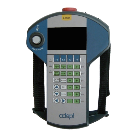
Chapter 4: Operation This chapter describes how to operate the T20 pendant. Before proceeding, you need to perform the steps covered in the Installation and Setup chapter. 4.1 Using the Pendant Controls and Indicators Figure 4-1. T20 Pendant Controls and LEDs T20 Pendant User's Guide, 10433-000 Rev. - Page 16 Button cycle through the connected robots. The currently selected robot is displayed in the Selected Robot indicator on the display screen. The T20 pendant can move multiple robots independently and sequentially, but cannot move multiple robots simultaneously. Menu Button Press to display the Home 1 screen.
-
Page 17: Enable Switch
Also indicates that the system is not in COMP mode. Figure 4-2. Numbered Index to T20 Buttons 4.2 Enable Switch The pendant is equipped with a 3-position enable switch. The enable switch is located on the back of the pendant, as shown in the following figure. - Page 18 Table 4-2. Enable Switch Positions on Pendant Switch Function Switch Position Contacts Home Not pressed (out) Open Enable Partially pressed (half-way, in middle position) Closed Panic Fully pressed (in) Open T20 Pendant User's Guide, 10433-000 Rev. E Page 18 of 50...
-
Page 19: Turning Power On And Off
When the system is set to Manual mode and you release the enable switch (or select the "panic" position), the system turns off in a controlled manner. This puts the system in a dif- ferent state than when the E-Stop button is pressed. T20 Pendant User's Guide, 10433-000 Rev. E Page 19 of 50... -
Page 20: Turning Off Power From The T20 Pendant
Release or fully press the enable switch (only available when the system is in Manual mode) 4.4 User Interface Operation This section describes how to use the T20 user interface. User Interface Controls Figure 4-4. T20 Pendant Indicators T20 Pendant User's Guide, 10433-000 Rev. E... -
Page 21: User Interface Flow Diagram
NOTE: This indicator flashes when the robot number changes. User Interface Flow Diagram The following diagram shows the flow of the T20 pendant user interface. Please note the fol- lowing: The Menu button always returns you to the Home 1 screen. See the next section. - Page 22 Expanded Array Expanded Array Tool Display Info Error List (If the level above (If the level above was an array) was an array) Figure 4-5. User Interface Flow Diagram T20 Pendant User's Guide, 10433-000 Rev. E Page 22 of 50...
-
Page 23: Displaying The Home Screens
4.4 User Interface Operation Displaying the Home Screens Pressing the Menu button on the T20 pendant displays the Home 1 screen as shown below. There are two Home screens. Use the Next > soft key to switch between them. Figure 4-6. Home 1 Screen The following table describes the soft keys shown on the Home 1 screen. -
Page 24: Using Jog Mode
In COMP mode, an executing program or the system terminal has control of the robot. To select COMP mode, press the Jog Mode button until COMP is displayed in the Jog Mode indic- ator. T20 Pendant User's Guide, 10433-000 Rev. E Page 24 of 50... -
Page 25: Joint Mode
'–' button to move the robot joint in the negative direction. World Mode When World mode is selected, movement in the X, Y, or Z direction is parallel to an axis of the World coordinate system. T20 Pendant User's Guide, 10433-000 Rev. E Page 25 of 50... -
Page 26: Tool Mode
The Tool coordinate system is centered at the robot tool flange with the Z- axis pointing away from the flange. On most robots, the positive X-axis is aligned with the cen- ter of the tool flange keyway. T20 Pendant User's Guide, 10433-000 Rev. E Page 26 of 50... -
Page 27: Free Mode
As soon as another jog control mode is selected, all joints are returned to servo control and will not move freely. On some robots, Free mode is disabled for some of the joints. T20 Pendant User's Guide, 10433-000 Rev. E Page 27 of 50... -
Page 28: Speed Control
In other modes, the speed control and speed indicator pertain to jog speed. Jog speed is the percentage of the speed in manual mode, which is settable in the ACE software with the manual control maximum speed parameter. T20 Pendant User's Guide, 10433-000 Rev. E Page 28 of 50... -
Page 29: Position Display
ACE software Gripper object signals. (For details on the Gripper object, see the corresponding topic in ACE User's Guide.) Press Loc to display the Available Locations screen. T20 Pendant User's Guide, 10433-000 Rev. E Page 29 of 50... -
Page 30: Smart Locations
Frame jog mode. When this is done, the jog controls will move the robot in relation to the selected frame, rather than the World coordinates (robot base). T20 Pendant User's Guide, 10433-000 Rev. E Page 30 of 50... -
Page 31: Enable Frame-Based Jogging
4.10 Available Tools The Available Tools screen provides the ability to view and set a tool transformation (or off- set). T20 Pendant User's Guide, 10433-000 Rev. E Page 31 of 50... -
Page 32: Location Teaching
4.11 Location Teaching Press the Loc soft key from the pendant Home 1 screen to display the Available Locations screen shown in the following figure. T20 Pendant User's Guide, 10433-000 Rev. E Page 32 of 50... - Page 33 Shows the current position of the robot. Teach Teaches the current position to the selected location. Creates a new location named pendant.loc[X] where X is the first available value (1,2,3...). T20 Pendant User's Guide, 10433-000 Rev. E Page 33 of 50...
- Page 34 1. From the Available Locations screen, press the up/down arrow buttons to select the desired array, and then press Expand. The valid members of the selected array are dis- played. T20 Pendant User's Guide, 10433-000 Rev. E Page 34 of 50...
-
Page 35: Adding Approach Distance
I/O Signals feature allows users to toggle outputs ON (active, high) and OFF (inactive, low). Round icons represent input signals; square icons represent output signals. The available sig- nal types are: digital output, digital input, soft, and robot. T20 Pendant User's Guide, 10433-000 Rev. E Page 35 of 50... - Page 36 If more than one screen full of signals is displayed, press PgUp/PgDn soft keys to scroll through the screens. 3. For output signals, press the Toggle soft key to turn the selected signal ON or OFF. T20 Pendant User's Guide, 10433-000 Rev. E Page 36 of 50...
-
Page 37: Displaying And Clearing Errors
While the error screen is displayed, the Menu button, arrow buttons, and soft keys are dis- abled. Even though the soft keys remain blue, they are not active in this state. T20 Pendant User's Guide, 10433-000 Rev. E Page 37 of 50... - Page 38 This message is not affected by the Pendant Msgs setting. You can display a list of errors that have occurred since the pendant was last powered up. For details, see Displaying Recent Errors on page 43. T20 Pendant User's Guide, 10433-000 Rev. E Page 38 of 50...
-
Page 39: Chapter 5: Maintenance
For details, see Enabling Smart Locations on page 41. Approach Dist Sets the approach distance (1 mm to 200 mm). For details, see Setting the Approach Distance on page 41. T20 Pendant User's Guide, 10433-000 Rev. E Page 39 of 50... -
Page 40: Setting The Screen Saver
Thirty Seconds One Minutes Two Minutes Five Minutes Ten Minutes Twenty Minutes One Hour 5. Press OK to accept the change. Press Cancel to revert to the previous setting. T20 Pendant User's Guide, 10433-000 Rev. E Page 40 of 50... -
Page 41: Setting The Initial Speed
4. Press the up/down arrow buttons to select a value from 1 mm to 200 mm. 5. Press OK to accept the change. Press Cancel to revert to the previous setting. T20 Pendant User's Guide, 10433-000 Rev. E Page 41 of 50... -
Page 42: Enabling Pendant Messages
5.6 Enabling Pendant Messages You can disable all error messages except the Connection Lost screen, which is displayed if the T20 pendant ever loses connection to the SmartController EX motion controller. To enable the display of error messages on the pendant: 1. -
Page 43: Displaying Recent Errors
3. Press the Errors soft key. The Recent Errors screen opens. 4. If necessary, press the up/down arrow buttons to select the error of interest. 5. Press the Detail soft key to display details about the selected error. T20 Pendant User's Guide, 10433-000 Rev. E Page 43 of 50... -
Page 44: Updating The Pendant Firmware
Chapter 5: Maintenance Figure 5-3. Recent Errors and Detail Screens 6. Press List to return to the Recent Errors screen. 5.9 Updating the Pendant Firmware To update the pendant firmware: T20 Pendant User's Guide, 10433-000 Rev. E Page 44 of 50... - Page 45 "\T20Update". Figure 5-4. Location for Inserting Micro SD Card in Pendant 3. Reapply power to the controller, or reconnect the T20 pendant to the controller, depend- ing on how you removed power. 4. After a reboot, on the Home 1 screen, press Next > to display the Home 2 screen.
-
Page 46: Loss Of Connection
If this state persists, contact your sales representative for assistance. 5.11 Cleaning To clean the T20 pendant, use a soft cloth dampened with a small amount of water or a mild cleaning agent. CAUTION: Never clean the T20 pendant display screen or other sur- faces with solvents, abrasive cleaners, or scrubbing sponges. -
Page 47: Chapter 6: Technical Specifications
Chapter 6: Technical Specifications 6.1 Dimension Drawings Figure 6-1. T20 Pendant Dimensions 6.2 Pendant Specifications Table 6-1. T20 Pendant Specifications Description Specification Physical Length 224 mm (8.8 in.) T20 Pendant User's Guide, 10433-000 Rev. E Page 47 of 50... - Page 48 UL 94-V0 Environmental Operating 0° to 45° C (32° to 113° F) Temperature Storage Temperature -25° to 60° C (-13° to 140° F) Relative Humidity 5 to 95% (non-condensing) T20 Pendant User's Guide, 10433-000 Rev. E Page 48 of 50...
- Page 50 OMRON ADEPT TECHNOLOGIES, INC. No. 438A Alexandra Road # 05-05/08 (Lobby 2), 4550 Norris Canyon Road, Suite 150, San Ramon, CA 94583 U.S.A. © OMRON Corporation 2016 All Rights Reserved. Alexandra Technopark, Tel: (1) 925-245-3400/Fax: (1) 925-960-0590 In the interest of product improvement,...
Need help?
Do you have a question about the T20 and is the answer not in the manual?
Questions and answers