Table of Contents
Advertisement
Operating instructions
Multifunctional safety controller
Operating instructions. . . . . . . . . . . .pages 1 to 20
EN
Original
Content
1
1.1 Function . . . . . . . . . . . . . . . . . . . . . . . . . . . . . . . . . . . . . . . . . . . . . .2
1.2 Target group: authorised qualified personnel. . . . . . . . . . . . . . . . . .2
1.3 Explanation of the symbols used . . . . . . . . . . . . . . . . . . . . . . . . . . .2
1.4 Appropriate use . . . . . . . . . . . . . . . . . . . . . . . . . . . . . . . . . . . . . . . .2
1.5 General safety instructions . . . . . . . . . . . . . . . . . . . . . . . . . . . . . . .2
1.6 Warning about misuse . . . . . . . . . . . . . . . . . . . . . . . . . . . . . . . . . . .2
1.7 Exclusion of liability . . . . . . . . . . . . . . . . . . . . . . . . . . . . . . . . . . . . .2
2
2.1 Ordering code . . . . . . . . . . . . . . . . . . . . . . . . . . . . . . . . . . . . . . . . .2
2.2 Special versions. . . . . . . . . . . . . . . . . . . . . . . . . . . . . . . . . . . . . . . .2
2.3 Destination and use . . . . . . . . . . . . . . . . . . . . . . . . . . . . . . . . . . . . .2
2.4 Technical data . . . . . . . . . . . . . . . . . . . . . . . . . . . . . . . . . . . . . . . . .3
2.5 Safety classification . . . . . . . . . . . . . . . . . . . . . . . . . . . . . . . . . . . . .4
3
3.1 General mounting instructions . . . . . . . . . . . . . . . . . . . . . . . . . . . . .4
3.2 Disassembly. . . . . . . . . . . . . . . . . . . . . . . . . . . . . . . . . . . . . . . . . . .4
3.3 Disposal . . . . . . . . . . . . . . . . . . . . . . . . . . . . . . . . . . . . . . . . . . . . . .4
4
4.1 General information for electrical connection. . . . . . . . . . . . . . . . . .4
4.2 Power supply . . . . . . . . . . . . . . . . . . . . . . . . . . . . . . . . . . . . . . . . . .4
4.3 Start level . . . . . . . . . . . . . . . . . . . . . . . . . . . . . . . . . . . . . . . . . . . . .4
4.4 Sensor level . . . . . . . . . . . . . . . . . . . . . . . . . . . . . . . . . . . . . . . . . . .4
4.5 Actuator level . . . . . . . . . . . . . . . . . . . . . . . . . . . . . . . . . . . . . . . . . .5
5
5.1 Connection / operating elements . . . . . . . . . . . . . . . . . . . . . . . . . . .6
5.2 Description of the terminals . . . . . . . . . . . . . . . . . . . . . . . . . . . . . . .6
5.3 Start level . . . . . . . . . . . . . . . . . . . . . . . . . . . . . . . . . . . . . . . . . . . . .6
5.4 Sensor level . . . . . . . . . . . . . . . . . . . . . . . . . . . . . . . . . . . . . . . . . . .6
5.5 Actuator level . . . . . . . . . . . . . . . . . . . . . . . . . . . . . . . . . . . . . . . . . .7
5.6 Project planning . . . . . . . . . . . . . . . . . . . . . . . . . . . . . . . . . . . . . . . .7
5.7 Configuration . . . . . . . . . . . . . . . . . . . . . . . . . . . . . . . . . . . . . . . . . .7
6
6.1 Operating the safety module . . . . . . . . . . . . . . . . . . . . . . . . . . . . . .9
6.2 Putting into operation for the first time . . . . . . . . . . . . . . . . . . . . . . .9
6.3 Configuration . . . . . . . . . . . . . . . . . . . . . . . . . . . . . . . . . . . . . . . . . .9
6.4 Behaviour in the case of faults. . . . . . . . . . . . . . . . . . . . . . . . . . . . .9
6.5 Maintenance . . . . . . . . . . . . . . . . . . . . . . . . . . . . . . . . . . . . . . . . .10
7
7.1 Menu structure - Safety module. . . . . . . . . . . . . . . . . . . . . . . . . . .10
8
8.1 Application programs . . . . . . . . . . . . . . . . . . . . . . . . . . . . . . . . . . . 11
8.2 Error message, warning and status indication . . . . . . . . . . . . . . . .19
9
EN
PROTECT SELECT
PROTECT SELECT OEM
1
Advertisement
Table of Contents

Subscribe to Our Youtube Channel
Related Manuals for schmersal PROTECT SELECT


Summary of Contents for schmersal PROTECT SELECT
-
Page 1: Table Of Contents
Operating instructions PROTECT SELECT Multifunctional safety controller PROTECT SELECT OEM Content About this document 1.1 Function ..........2 1.2 Target group: authorised qualified personnel. -
Page 2: About This Document
The safety-relevant current paths with the outputs Q0 to Q3 meet the following requirements under observation of a B10d value assessment Further technical information can be found in the Schmersal (also refer to chapter 2.5 "Safety classification"): catalogues or in the online catalogue on the Internet: –... -
Page 3: Technical Data
Operating instructions PROTECT SELECT Multifunctional safety controller PROTECT SELECT OEM 2.4 Technical data Safe semi-conductor outputs General data Number (p-/n-switching): Standards: EN 60204-1 ; EN 60947-5-1; EN 62061; - Note: with OEM -version an activation of the second ISO 13849-1; IEC 61508 p+n-switching output Q1/Q1N is possible. -
Page 4: Safety Classification
Operating instructions PROTECT SELECT Multifunctional safety controller PROTECT SELECT OEM 2.5 Safety classification 4. Electrical connection Standards: EN ISO 13849-1; IEC 62061; EN 60947-5-1; IEC 61508 4.1 General information for electrical connection up to e Control category: up to 4... -
Page 5: Actuator Level
Test pulses Proximity switches with Reed contacts (e.g. safety switches such as the Schmersal BNS type series) may not be The correct function of the semi-conductor outputs is secured by a connected to inputs (I0, I4, I12, I14) due to the alternative cyclical test, i.e. -
Page 6: Operating Principle And Settings
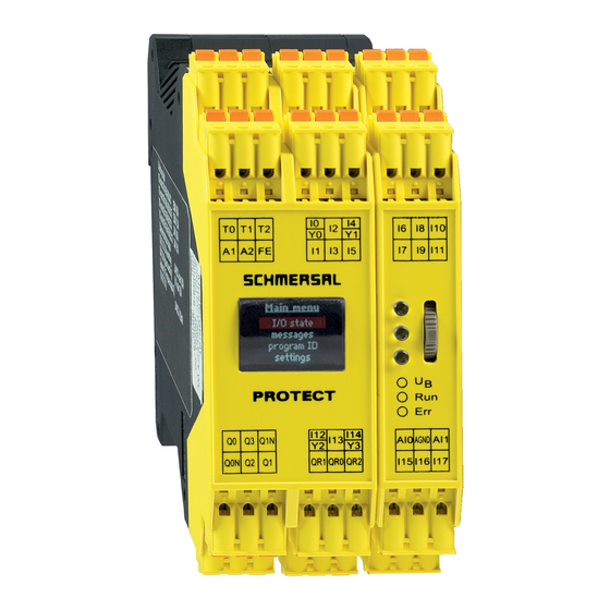
Operating instructions PROTECT SELECT Multifunctional safety controller PROTECT SELECT OEM 5. Operating principle and settings 5.3 Start level Alternatively: auto-start or manual start (falling edge) 5.1 Connection / operating elements Optional: feedback circuit (EDM), start-up testing 1 Cycle outputs T0...T2... -
Page 7: Actuator Level
Operating instructions PROTECT SELECT Multifunctional safety controller PROTECT SELECT OEM 5.5 Actuator level The entry of the MSP code is from right to left. The actuator level consists of: Sensor type Feature 2x p-/n-switching safe outputs code (1st position) 2x p-switching safe outputs... - Page 8 Operating instructions PROTECT SELECT Multifunctional safety controller PROTECT SELECT OEM The interlock type always applies to all connected guard Additional functions (2nd Stelle) interlocks. Discrepancy error Start-up test Feedback Autostart code monitoring circuit Analog inputs • Dual Sensor 2-channel analysis of AI0 and AI1 with percentage •...
-
Page 9: Set-Up And Maintenance
8. The list of the MSP codes now appears for the Input circuit code 3. ERR LED dark: Fault cannot be diagnosed by PROTECT SELECT. MSP 01: 1 A 5 input circuits. Set the corresponding code for... -
Page 10: Maintenance
Operating instructions PROTECT SELECT Multifunctional safety controller PROTECT SELECT OEM Configuration 6.5 Maintenance A regular visual inspection and functional test, including the following Enter PIN steps, is recommended: Entry of the PIN codes so as be able to perform the 1. -
Page 11: Appendix
Emergency Stop The programs listed here are valid only for the standard Description: variant PROTECT SELECT and version 2.0 of the application • Additional release for the interlock: program (printed safety seal "Appl V2.0"). If an interlock is parameterized and the two analogue input values are... - Page 12 Operating instructions PROTECT SELECT Multifunctional safety controller PROTECT SELECT OEM DESCRIPTION: Application program 01 TOF: Timer, shutdown delay TON: Timer, switch on delay Prog_01: A safety area, visible from control area, enabling switches + operating mode selector switch, 4 x individual sensors,...
- Page 13 Operating instructions PROTECT SELECT Multifunctional safety controller PROTECT SELECT OEM Safe semi-conductor outputs Q2, Q3 In addition, the inputs can be changed as individual sensors I16 and I17 together with the default setting "Emergency Stop command device". • Stop 0 or Stop 1: This sensor evaluation for the inputs I16 and I17 have a higher priority All semiconductor outputs are linked to a safe timer (Timer Off Delay).
- Page 14 Operating instructions PROTECT SELECT Multifunctional safety controller PROTECT SELECT OEM Application program 02 First and second safety areas The inputs I16 and I17 (default setting: emergency stop) switch off all Prog_02: Two safety areas, visible from control area, the parent outputs Q0 to Q2 and from QR1 to QR2.
- Page 15 Operating instructions PROTECT SELECT Multifunctional safety controller PROTECT SELECT OEM Timers used Application program 03 Name Function Timer Time [s] Prog_03: One safety area, visible from control area, 5 x individual sensors, TOF 0 Shut down delay for Q0/Q0N 0.00...
- Page 16 Operating instructions PROTECT SELECT Multifunctional safety controller PROTECT SELECT OEM Digital inputs I00, I01, I13, I15 Application program 04 • Input I00 (RESET): - Restart condition of the safety sensors, connected to the inputs Prog_04: One safety area with muting, visible from control area, I02 to I11.
- Page 17 Operating instructions PROTECT SELECT Multifunctional safety controller PROTECT SELECT OEM Digital inputs I09, I13, I15 Timers used • Input I09 (unlock interlock: "Open door request"): Name Function Timer Time [s] - Request to unlock the guard interlock so that the safety area can be accessed.
- Page 18 Operating instructions PROTECT SELECT Multifunctional safety controller PROTECT SELECT OEM Operating principle: Muting Fault situation 1 Muting is the temporary bypassing of a safety light barrier if required a. The light grid (AOPD) is interrupted: by the duty cycle. There must be a voltage applied to the muting inputs - The muting outputs are switched off.
-
Page 19: Error Message, Warning And Status Indication
Operating instructions PROTECT SELECT Multifunctional safety controller PROTECT SELECT OEM 8.2 Error message, warning and status indication Display indications Comment (depending on the application program) Error - Both inputs on which the operating mode selector switch is connected have the same signal ■... -
Page 20: Eu Declaration Of Conformity
Managing Director The currently valid declaration of conformity can be downloaded from the internet at www.schmersal.net. The PROTECT SELECT OEM is supplied with a separate K. A. Schmersal GmbH & Co. KG declaration of conformity. Möddinghofe 30, D - 42279 Wuppertal...
Need help?
Do you have a question about the PROTECT SELECT and is the answer not in the manual?
Questions and answers