Advertisement
Quick Links
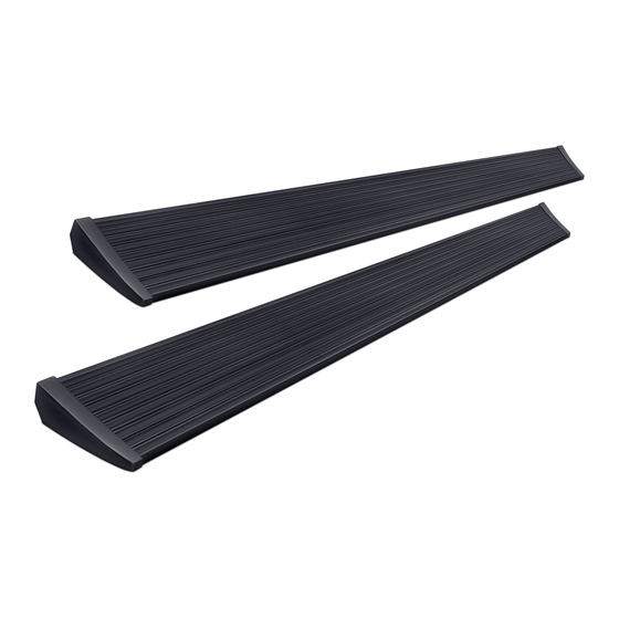
APPLICATION
Ford Ranger - Super Crew
Ford Ranger - Super Cab
AMP RESEARCH TECH SUPPORT 1-888-983-2204 (Press 2) Monday - Friday, 7:00 AM - 5:00 PM PST
Invented, engineered and manufactured exclusively by AMP Research in the USA. May be covered by one of the following patents:
6,641,158; 6,830,257; 6,834,875; 6,938,909; 7,055,839; 7,380,807; 7,398,985; 7,584,975 ©2012 AMP Research. All rights reserved.
Printed in USA.
www.amp-research.com
I N S T A L L A T I O N G U I D E
1/12
LENGTH
MODEL YR
72"
65"
q Safety goggles
q Measuring tape
q 10 mm socket
q 10 mm ratchet wrench
q 13 mm ratchet wrench
q 15 mm ratchet wrench
q Ratchet wrench and extension
q Pliers
q Wire crimpers
q Wire stripper / cutter
q 3/16" H ex key wrench (allen wrench)
q Electrical tape
q Weather proof caulking (silicone sealer)
q 1/8" Drill bit
q 9/32" Drill bit
q Drill
q Heat Gun
5-Year Limited Warranty
PART #
2019
76136-01A
2019
76136-01A
INSTALLATION TIME
3-5 Hours
Professional installation recommended
SKILL LEVEL
2
3
1
4= Experienced
TOOLS REQUIRED
WARRANTY
IM76136 rev 12.11.19
4
Advertisement

Related Manuals for AMP Research PowerStep 76136-01A


Summary of Contents for AMP Research PowerStep 76136-01A
- Page 1 AMP RESEARCH TECH SUPPORT 1-888-983-2204 (Press 2) Monday - Friday, 7:00 AM - 5:00 PM PST Invented, engineered and manufactured exclusively by AMP Research in the USA. May be covered by one of the following patents: 6,641,158; 6,830,257; 6,834,875; 6,938,909; 7,055,839; 7,380,807; 7,398,985; 7,584,975 ©2012 AMP Research. All rights reserved.
-
Page 2: Exploded View
A M P R E S E A R C H P O W E R S T E P – F O R D R A N G E R INSTALLATION GUIDE Attaching motor to Linkage assembly The motors must be attached to the Linkage assemblies on step 5 EXPLODED VIEW •... - Page 3 A M P R E S E A R C H P O W E R S T E P – F O R D R A N G E R COMPONENT/PARTS IDENTIFICATION Note: Some Applications require modification. Application Cut Length Crew Cab 72”...
- Page 4 A M P R E S E A R C H P O W E R S T E P – F O R D R A N G E R Wire Harness ODB II Plug Controller STA Motor Cover Motor LED Lamp Hex Flange Bolt...
- Page 5 A M P R E S E A R C H P O W E R S T E P – F O R D R A N G E R Cinch Fastener Grommet Cable Tie 11” Cable Tie 7” M8 Head Hex Bolt Butt Connector www.amp-research.com...
- Page 6 A M P R E S E A R C H P O W E R S T E P – F O R D R A N G E R Locate Front Idler linkage location. If plastic Pre thread supplied M10 flange bolt and hook plugs are present remove plastic plugs to linkage over bolt as shown.
- Page 7 A M P R E S E A R C H P O W E R S T E P – F O R D R A N G E R Install board to linkages. Measure approx. 4.5” Install motor onto linkages using supplied from back of linkage to the tip of the board as Hex head bolts (18).
- Page 8 A M P R E S E A R C H P O W E R S T E P – F O R D R A N G E R Route the two wire harness legs down over to each Remove floor mat and sill plate cover to wheel well.
- Page 9 A M P R E S E A R C H P O W E R S T E P – F O R D R A N G E R Locate OBD port and remove bolt and nut holding it in place with 8mm socket to gain better access to back side of plug.
- Page 10 A M P R E S E A R C H P O W E R S T E P – F O R D R A N G E R Use supplied posi lock connectors to attach the 2 purple wires of the obd harness to the main harness.
- Page 11 A M P R E S E A R C H P O W E R S T E P – F O R D R A N G E R Insert grommet into drilled holes. Insert lamp wires through the grommets. (Silicon lube will help wires slip through grommets).
-
Page 12: Final System Check
A M P R E S E A R C H P O W E R S T E P – F O R D R A N G E R Insert plug from wire harness (4) onto motor (7). Insert plastic push pin rivets (14) in mounting holes Slide rubber grommet on wire harness into slot of of motor cover (8). -
Page 13: Year Limited Warranty
5-YEAR LIMITED WARRANTY AMP RESEARCH warrants this product to be free from defects in material and workmanship for FIVE (5) YEARS FROM DATE OF PURCHASE, provided there has been normal use and proper maintenance. This warranty applies to the original purchaser only.
Need help?
Do you have a question about the PowerStep 76136-01A and is the answer not in the manual?
Questions and answers