Table of Contents
Advertisement
Quick Links
APPLICATION
Sprinter Van
(2 - sided)
AMP RESEARCH TECH SUPPORT 1-888-983-2204 (Press 2) Monday - Friday, 7:00 AM - 5:00 PM PST
Invented, engineered and manufactured exclusively by AMP Research in the USA. May be covered by one of the following patents:
6,641,158; 6,830,257; 6,834,875; 6,938,909; 7,055,839; 7,380,807; 7,398,985; 7,584,975 ©2012 AMP Research. All rights reserved.
Printed in USA.
www.amp-research.com
I N S T A L L A T I O N G U I D E
MODEL YR
2007 - 2018
1/14
PART #
76263-01A
INSTALLATION TIME
3-5 Hours
Professional installation recommended
SKILL LEVEL
2
3
1
4= Experienced
TOOLS REQUIRED
q Safety goggles
q Measuring tape
q 13mm wrench
q 19mm wrench
q 13mm socket
q 10mm socket
q Ratchet wrench and extension
q Wire stripper / cutter
q 3/16" hex key (allen wrench)
q 4mm hex key (allen wrench)
q Electrical tape
q T25 Torx Driver
WARRANTY
5-Year Limited Warranty
IM76263 rev 01.21.20
4
Advertisement
Table of Contents

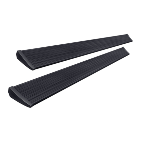
Summary of Contents for AMP Research PowerStep 76263-01A
- Page 1 AMP RESEARCH TECH SUPPORT 1-888-983-2204 (Press 2) Monday - Friday, 7:00 AM - 5:00 PM PST Invented, engineered and manufactured exclusively by AMP Research in the USA. May be covered by one of the following patents: 6,641,158; 6,830,257; 6,834,875; 6,938,909; 7,055,839; 7,380,807; 7,398,985; 7,584,975 ©2012 AMP Research. All rights reserved.
-
Page 2: Exploded View
A M P R E S E A R C H P O W E R S T E P – S P R I N T E R INSTALLATION GUIDE Attaching motor to linkage assembly The motors must be attached to the linkage assemblies before continuing the installation process. - Page 3 A M P R E S E A R C H P O W E R S T E P – S P R I N T E R (A) End cap left (x1) (B) End cap right (x1) (C) T-nut insert (x2) (D) Socket cap screw (x2) (E) End cap wedge right (x1) (F) End cap wedge left (x1)
- Page 4 A M P R E S E A R C H P O W E R S T E P – S P R I N T E R PARTS LIST AND HARDWARE IDENTIFICATION Washer (SS) Wire Harness Controller STA M8 Hex bolt Posi-Splice Connector Cable Tie (7”)
- Page 5 A M P R E S E A R C H P O W E R S T E P – S P R I N T E R PARTS LIST AND HARDWARE IDENTIFICATION M8 small head Butt Connector Rivet Nut Tool LED Lamp Hex bolt Bracket (Driver Front)
-
Page 6: Passenger Side
A M P R E S E A R C H P O W E R S T E P – S P R I N T E R Passenger Side Rear Drive Linkage install: Locate rear linkage Set Upper mount up to bump in sheetmetal and mark side of linkage near mounting slot. -
Page 7: Driver Side
A M P R E S E A R C H P O W E R S T E P – S P R I N T E R Pre Drill holes with an 1/8” Drill and then drill to Front Idler Linkage Install: Locate front linkage 17/32”. - Page 8 A M P R E S E A R C H P O W E R S T E P – S P R I N T E R Pre Drill holes with an 1/8” Drill and then drill to Locate Driver side rear Drive linkage location.
- Page 9 A M P R E S E A R C H P O W E R S T E P – S P R I N T E R Remove bracket bolts on side of upper mount to With front bracket in place mark hole. Center punch, rotate out of way.
- Page 10 A M P R E S E A R C H P O W E R S T E P – S P R I N T E R Remove Fuses. Connect positive terminal on power lead using a 10mm socket or wrench. Connect ground to body ground in bottom of seat box.
- Page 11 A M P R E S E A R C H P O W E R S T E P – S P R I N T E R Remove dash cover panel using a T25 Torx driver. Once cover is removed locate black BUS Connector and lift off fram e to allow for easier install.
- Page 12 A M P R E S E A R C H P O W E R S T E P – S P R I N T E R Using supplied Posi Spice connectors connect Secure module and wires up under dash using matching wire colors together.
- Page 13 A M P R E S E A R C H P O W E R S T E P – S P R I N T E R Some vehicles may have a shield shown. Verify Board does not come in contact with shield.
-
Page 14: Final System Check
A M P R E S E A R C H P O W E R S T E P – S P R I N T E R Using supplied butt connectors, connect the lamp Close and wrap with conduit and electrical tape. wires. -
Page 15: Year Limited Warranty
5-YEAR LIMITED WARRANTY AMP RESEARCH warrants this product to be free from defects in material and workmanship for FIVE (5) YEARS FROM DATE OF PURCHASE, provided there has been normal use and proper maintenance. This warranty applies to the original purchaser only.


Need help?
Do you have a question about the PowerStep 76263-01A and is the answer not in the manual?
Questions and answers