Table of Contents
Advertisement
Quick Links
Advertisement
Table of Contents

Subscribe to Our Youtube Channel
Related Manuals for Efco SmartSL


Summary of Contents for Efco SmartSL
- Page 1 SmartSL Compact Fanless Box Computer User Manual Version 1.1...
- Page 2 SmartSL User Manual Preface Revision History Revision Date Author Description 2018/07/12 Edition release 2020/04/07 J Marengo Update...
- Page 3 No part of this manual may be reproduced, copied, translated, or transmitted in any form or by any means without the prior written permission of EFCO. Information provided in this manual is intended to be accurate and reliable.
- Page 4 SmartSL User Manual Warnings, Cautions, and Notes...
- Page 5 SmartSL User Manual Safety Instructions Please read the following safety instructions carefully. It is advised that you keep this manual for future reference. 1. All cautions and warnings on the device should be noted. 2. Make sure the power source matches the power rating of the device.
-
Page 6: Table Of Contents
SmartSL User Manual Table of Contents Preface Chapter 1 General Introduction ..............1 Overview ...................... 2 Common Specifications ..................3 Supported CPU List ..................4 Packing List ....................4 Ordering Information ..................4 Chapter 2 Mechanical Dimensions ............5 Top View ...................... 6 Front View .................... - Page 7 SmartSL User Manual Advanced Setup ..................37 6.4.1 Watchdog Submenu ..................... 38 6.4.2 Hardware Health Monitoring Submenu ..............38 6.4.3 Graphics Submenu ....................39 6.4.4 Intel® Ethernet Connection I210 Submenu ............39 6.4.5 Intel® Ethernet Connection I211 Submenu ............40 6.4.6...
-
Page 8: Chapter 1 General Introduction
SmartSL User Manual Chapter 1 General This chapter includes: Overview Introduction Product Features Specifications Supported CPU List Packing List Ordering Information... -
Page 9: Overview
SmartSL User Manual Overview The SmartSL is a compact fanless box computer that has an ultra-slim size with an aluminum alloy structure. The SmartSL series support 3rd Generation Intel® Atom™ Processor, Celeron® Processor (formerly Bay Trail platform), and is designed for... -
Page 10: Common Specifications
SmartSL User Manual Common Specifications Model Name U7-150 U7-130 U7-131 Mechanical Dimensions 173 mm x 88 mm x 21.7 mm (6.81” x 3.46” x0.85”) Weight 0.75kg Mounting 2x wall mount brackets Construction Aluminum alloy structure Battery System Intel ® Platform... -
Page 11: Supported Cpu List
Intel® Celeron® N2807 1.58 GHz Dual Core L2 cache 1MB 4.5W TDP Packing List When you receive the package of the SmartSL, please check immediately if the package contains all the items listed in the following table. If any item is missing or damaged, please contact your local dealer or EFCO for further assistance. -
Page 12: Mechanical Dimensions
SmartSL User Manual Chapter 2 Mechanical This chapter includes: Dimensions Top View Front View Rear View Left-Side View Right-Side View Bottom View... -
Page 13: Top View
SmartSL User Manual Top View Unit: mm Front View Unit: mm Rear View Unit: mm... -
Page 14: Right-Side View
SmartSL User Manual Right-Side View Unit: mm Left-Side View Unit: mm Bottom View Unit: mm... - Page 15 SmartSL User Manual...
-
Page 16: Hardware Function Description
SmartSL User Manual Chapter 3 Hardware This chapter includes: Function I/O Layout Description Front Panel I/O Function Rear Panel I/O Function Right-Side I/O Function SSD Drive Bay IOM Card Expansion... -
Page 17: I/O Layout
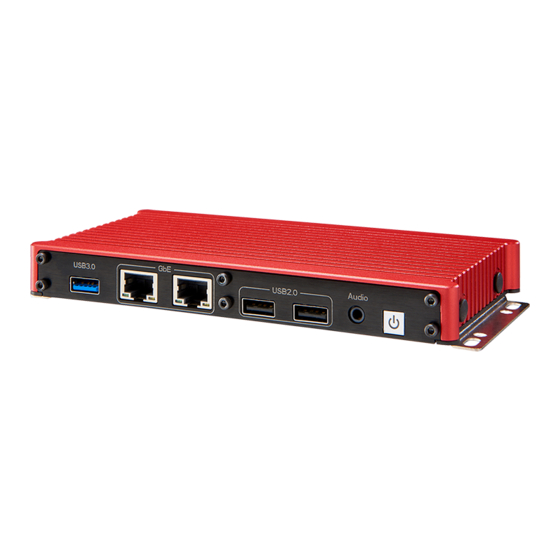
SmartSL User Manual I/O Layout The SmartSL provides sufficient I/O ports on the front panel, rear panel, right-side, and left-side panel. Front I/O Power USB 2.0 USB 3.0/2.0 Audio Button Rear I/O DC-In USB 2.0 RS-232 GPIO... -
Page 18: Front Panel I/O Function
SmartSL, press the power button, and the Green LED will light up. To turn off the SmartSL, a command in the OS can be issued to shut down the system, or just simply press the power button. To force a hard reset, press and hold the power button for 5 seconds to manually shut down the system. -
Page 19: Line-Out And Mic-In Audio Jacks
Right Audio output signal Audio L Left Audio output signal Audio Ground 3.2.3 USB 2.0 Ports The SmartSL provides four USB 2.0 Type A connectors. Two ports on the front side and two ports on the rear side. PIN Name Description +5 VDC... -
Page 20: Gigabit Ethernet Port
SmartSL User Manual 3.2.4 Gigabit Ethernet Port ® The SmartSL offers two Gigabit Ethernet (GbE) ports that use Intel i210 Gigabit Ethernet controllers. The GbE ports are located on the front panel and will support Wake-on-LAN function. When you plug in the Ethernet cable, you will see the Ethernet status and speed from the LED indicators on the RJ45 connector as follows: 1000 Base-T uses all pairs for bidirectional traffic in the RJ45 connector. -
Page 21: Usb 3.0 Connector
SmartSL User Manual 3.2.5 USB 3.0 Connector The SmartSL offers one USB 3.0 (SuperSpeed USB) port Type A connector on the front panel. The BIOS default is xHCI (Extensible Host Controller Interface) mode and is compatible with USB 3.0, USB 2.0, USB 1.1 and USB 1.0 devices. Legacy USB support is also provided so that you can use a USB keyboard/mouse in a DOS environment. -
Page 22: Rear Panel I/O Function
3.3.1 COM Port The SmartSL provides one UART port on the rear panel for communicating with external devices. COM1 is located on the back panel via 9-pin D-Sub male connectors. The UART ports support legacy speeds up to 115.2K bps as well as higher baud rates of 230K, 460K, or 921K bps to support higher-speed modems. -
Page 23: Dio (Digital Io)
SmartSL User Manual 3.3.2 DIO (Digital IO) The SmartSL offers 16-bit programmable digital input/output (DIO) for operating directly with TTL or 5-V CMOS devices. Each bit is programmable with software. Commented [JM1]: New Picture – remove HDMI GPIO 1 Table... -
Page 24: Usb 2.0 Port
SmartSL User Manual 3.3.3 USB 2.0 Port The SmartSL provides two additional ports for USB 2.0 Type A connectors on the rear panel. Commented [JM2]: New Picture Remove HDMI +5 VDC Data - Data + Ground 3.3.4 DDI Connector The SmartSL provides a high-resolution DDI display output on the front panel and will support display resolution up to 1920x1200. -
Page 25: Dc Jack For Dc Input
Commented [JM4]: Need new picture w/ HDMI Removed and the DDI Showing The SmartSL series allows a wide range of DC power input from 9V to 32V. It offers a 2-pin DC power jack. The 2-pin power connector is used to connect the power plug of an AC/DC adapter. -
Page 26: Left-Side And Right-Side Panel I/O Function
SmartSL offers more I/O functions on its Left-side and right-side panel. 3.3.1 Antenna Hole The SmartSL series provides three antenna holes for wireless applications. Left-side Panel Right-side Panel Internal I/O Functions SmartSL provides other useful features via the on-board connectors, such as one... -
Page 27: Mini Pci Express Connector (With Usim Socket)
SmartSL User Manual mSATA socket and two Mini PCIe sockets. The SmartSL provides two onboard full-length Mini PCIe slots with USIM sockets. By installing a Mini PCIe module, your system can support expanded features such as Wi-Fi, 3G, 4G, GPS, and Bluetooth. -
Page 28: Usim Socket
+3.3V +3.3V LED WWAN# LED WLAN# Reserved LED WPAN# Reserved +1.5V Reserved Reserved +3.3V 3.5.2 USIM Socket The SmartSL series provides 2 USIM sockets for wireless applications when a 3G/4G wireless module is installed into a full-length Mini PCIe socket. -
Page 29: Msata Socket
SPU, for either standard or proprietary use, as input and/or output. Input or Output for serial data (half-duplex) to the integrated circuit inside the card. RESERVED AUX2, optionally used for USB interfaces and other uses. 3.5.3 mSATA socket The SmartSL supports one mSATA SSD socket. - Page 30 SmartSL User Manual Top Side Bottom Side 3.3V Mechanical Key SATA_Rp0 +3.3V SATA_Rn0 SATA_Tn0 SATA_Tp0 +3.3V...
-
Page 31: Cmos Battery Connector
SmartSL User Manual +3.3V +3.3V 3.5.4 CMOS Battery connector 2-pin wafer, pitch 1.25mm Brand: TXGA Model name: FWF12506-S02S24W5M Name Function RTC Bat RTC Battery V+ RTC Battery Ground... -
Page 32: Chapter 4 Hardware Installation
SmartSL User Manual Chapter 4 Hardware This chapter includes: Installation LGA1151 CPU Installation and Replacement SO-DIMM Memory Installation Mini PCIe / mSATA Module Installation 2.5” SATA SSD/HDD Installation IOM Installation Mounting Bracket Installation... -
Page 33: Msata Ssd Installation
SmartSL User Manual 4.1 mSATA SSD Installation Remove the bottom screws and cover Find the mSATA socket... - Page 34 SmartSL User Manual Place the mSATA SSD module into the socket and fix the module with M2.5 screws. 4. Reinstall the bottom cover and screws.
-
Page 35: Mini Pcie Module Installation
SmartSL User Manual 4.2 Mini PCIe Module Installation Remove the bottom screws and cover 2. Find the full-length Mini PCIe socket... - Page 36 SmartSL User Manual 3. Place the Mini PCIe module into the socket and fix the module with M2.5 screws. Reinstall the bottom cover and screws...
-
Page 37: Usim Card Installation
SmartSL User Manual 4.3 USIM card installation Remove the bottom screws and cover 2. Find the USIM card socket and pull the locker open... - Page 38 SmartSL User Manual 3. Place the USIM card into the socket and pull the locker close. 4. Reinstall the bottom cover and screws.
-
Page 39: Chapter 5 Function Settings
SmartSL User Manual Chapter 5 Function Settings This chapter includes: Jumper Switch... -
Page 40: Jumper And Dip Switch
SmartSL User Manual Jumper and DIP Switch 5.1.1 Jumper You can configure your board to match the needs of your application by setting jumpers. A jumper is the simplest kind of electric switch. It consists of two metal pins and a small metal clip (often protected by a plastic cover) that slides over the pins to connect them. -
Page 41: At/Atx Power Mode Select
SmartSL User Manual 5.1.2 AT/ATX power mode select Closed PIN Function Note AT mode ATX mode Default... -
Page 42: Chapter 6 Bios Settings
SmartSL User Manual Chapter 6 BIOS Settings This chapter includes: Entering BIOS Setup Program Setup Menu and Navigation Advanced Setup Options... -
Page 43: Entering The Bios Setup Program
SmartSL User Manual Entering the BIOS Setup Program The BIOS setup program can be accessed by pressing the <DEL> or <ESC> key during POST. 6.1.1 Boot Selection Popup The BIOS offers the ability to access a Boot Selection Popup menu by pressing the <F11>... -
Page 44: Main Setup Screen
SmartSL User Manual Main Setup Screen When you first enter the BIOS setup, you will see the main setup screen. This screen displays the BIOS, processor, memory, and board information and is used for configuring the systems date and time. -
Page 45: Watchdog Submenu
SmartSL User Manual 6.4.1 Watchdog Submenu Feature Options Description POST Watchdog Disabled 30 seconds Configure POST Watchdog Intervals (minutes) 1, 2, 5, 10, 30 Decide if POST watchdog should be stopped during Stop for User Interaction Yes / No Setup of boot menu or while waiting for a password... -
Page 46: Graphics Submenu
SmartSL User Manual Feature Options Description Boot up fan speed in percent of the maximum Fan Speed Setting supported speed 100% 6.4.3 Graphics Submenu Feature Options Description Active LFP / EDP 6.4.4 Intel® Ethernet Connection I210 Submenu Feature Options Description... -
Page 47: Intel® Ethernet Connection I211 Submenu
SmartSL User Manual 6.4.5 Intel® Ethernet Connection I211 Submenu Feature Options Description Configure Boot Protocol, Wake on LAN, Link NIC Configuration submenu Speed and VLAN Identify the physical network port by blinking the Blink LEDs 0 - 15 associated LED UEFI Driver Displays the UEFI Driver version. -
Page 48: Trusted Computing Submenu
SmartSL User Manual 6.4.7 Trusted Computing Submenu Feature Options Description Enable or disable BIOS support for a security Disabled Security Device device. O.S. will not show the security device. Support TCG EFI protocol and INT1A interface will not Enabled be available. -
Page 49: Acpi Submenu
SmartSL User Manual 6.4.11 ACPI Submenu Feature Options Description Disabled Enable ACPI Auto Enables or Disables BIOS ACPI Auto Configuration Configuration. Enabled Enable or disable the system's ability to Disabled hibernate (operating system S4 sleep Hibernation Support state). This option may not be valid with Enabled some operating systems. -
Page 50: Console Redirection Settings Com2 Submenu
SmartSL User Manual 6.4.13 Console Redirection Settings COM2 Submenu Feature Options Description VT100 VT100+ Terminal Type Select the terminal type. VT-UTF8 ANSI 9600 19200 38400 Baud rate Select the baud rate. 57600 115200 Data Bits Set the number of data bits. -
Page 51: Legacy Console Redirection Settings Submenu
SmartSL User Manual 6.4.14 Legacy Console Redirection Settings Submenu Feature Options Description COM0 (Disabled) Select a COM port to display redirection Legacy Serial Redirection COM1 (Disabled) of Legacy OS and Legacy OPROM Port COM2 (PCI Bus0, Messages. Dev30, Func3) 6.4.15... -
Page 52: Ppm Configuration Submenu
SmartSL User Manual 6.4.16 PPM Configuration Submenu Feature Options Description Disabled EIST Enable/Disable Intel SpeedStep Enabled Disabled CPU C state Report Enable/Disable CPU C state report to OS Enabled This option controls Max C state that the processor Max CPU C-state will support. -
Page 53: Sata Submenu
SmartSL User Manual 6.4.18 SATA Submenu Feature Options Description Enabled SATA Controller Enable/Disable SATA Device Disabled SATA Mode Selection AHCI Determines how the SATA controller operates. Gen1 Select SATA Interface Speed, CHV A1 always SATA Interface Speed Gen2 with Gen1 Speed. -
Page 54: Lpss & Scc Configuration Submenu
SmartSL User Manual 6.4.19 LPSS & SCC Configuration Submenu Feature Options Description ACPI mode SCC eMMC Support PCI mode SCC eMMC Support Enable\Disable (D16:F0) Disabled Disable/Enable eMMC Secure Erase. When Enabled eMMC Secure Erase enabled, all the data on the eMMC will be Disabled erased. -
Page 55: Pci & Pci Express Submenu
SmartSL User Manual 6.4.20 PCI & PCI Express Submenu Feature Options Description 32 PCI Bus Clocks 64 PCI Bus Clocks 96 PCI Bus Clocks 128 Bus Clocks Value to be programmed into the PCI PCI Latency Timer latency timer register. -
Page 56: Uefi Network Stack Submenu
SmartSL User Manual 6.4.21 UEFI Network Stack Submenu Feature Options Description UEFI Network Stack Disabled Enable or disable the UEFI network stack. Enabled IPv4 PXE Support Disabled Enable IPv4 PXE boot support. If disabled IPv4 PXE boot option will not be created. -
Page 57: Info Report Configuration Submenu
SmartSL User Manual 6.4.23 Info Report Configuration Submenu Feature Options Description Disabled Post Report Post Report Support Enabled/Disabled Enabled Delay Time Post Report Wait Time: 0~10 Seconds Disabled Info Error Message Info Error Message Support Enabled/Disabled Enabled Disabled Summary Screen... -
Page 58: Diagnostic Settings Submenu
SmartSL User Manual 6.4.25 Diagnostic Settings Submenu Feature Options Description Disabled Select the relay interface to which the Relay Interface SMBus POST code will be redirected. BC Diagnostic Console Set the Address for the primary debug port. The standard address value is 0x80. -
Page 59: Security Configuration Submenu
SmartSL User Manual 6.4.27 Security Configuration Submenu Feature Options Description Enabled TXE HWRFPO Disabled Enabled TXE Firmware Update Disabled Enabled TXE EOP Message Send EOP Message Before entering OS Disabled 6.4.28 Intel RMT Configuration Submenu Feature Options Description Disabled Intel RMT (Ready Mode Technology) SSDT Intel RMT Support table will be loaded if enabled. -
Page 60: Chipset Setup
SmartSL User Manual Chipset Setup Select the Chipset tab from the setup menu to enter the Chipset setup screen. 6.5.1 Processor (Integrated Components) Submenu Feature Options Description Memory Information Total memory No option The total amount of memory detected by the system... - Page 61 SmartSL User Manual Feature Options Description 448M Select DVMT 5.0 Pre-Allocated (Fixed) DVMT Pre-Allocated 480M Graphics Memory size used by the Internal Continued Graphics Device. 512M 128MB Select DVMT 5.0 Total Graphics Memory size DVMT Total Gfx Mem 256MB used by the Internal Graphics Device.
-
Page 62: Graphics Power Management Control Submenu
SmartSL User Manual 6.5.1.2 Graphics Power Management Control Submenu Feature Options Description Enabled RC6(Render Standby) Check to enable render standby support. Disabled Enabled Power Meter Lock Enable/Disable Power Meter Lock. Disabled 6.5.1.3 Memory Configuration Options Submenu Feature Options Description Rank Margin Tool EV... -
Page 63: Platform Controller Hub (Pch) Submenu
SmartSL User Manual Feature Options Description Auto Select the number of channels - Auto = dual- Channel selection Single channel Dual NOTE: Only bits [3:1] are used for final channel 0 - F, default is select value. BMISC Channel Select Bits 3:0:... -
Page 64: Security Configuration Submenu
SmartSL User Manual Feature Options Description Serial IRQ Mode Continuous Configure serial IR mode. Enable the CLKRUN# logic to stop the LPC Disabled CLKRUN# Logic clocks when possible. Requires Serial IRQ Enabled Mode to be set to Quiet as well. -
Page 65: Usb Configuration Submenu
SmartSL User Manual 6.5.2.3 USB Configuration Submenu Feature Options Description Enabled XHCI Mode Mode of operation of xHCI controller Disabled Enabled SSIC Support Enable Enable/Disable SSIC Support Disabled SSIC initialization SSIC Initialization Sequence 1 - Windows, Sequence 1 SSIC Initialization... -
Page 66: Pci Express Root Port 1/2/3/4 Submenu
SmartSL User Manual 6.5.2.4.1 PCI Express Root Port 1/2/3/4 Submenu Feature Options Description Enabled Control the PCI Express Root Port. PCI Express Root Port 1 Disabled Auto Disabled PCI Express Active State Power ASPM Management settings. L0sL1 Disabled PCI Express Unsupported Request Reporting Enable/Disable. -
Page 67: Pci Express S0Ix Settings Submenu
SmartSL User Manual Tx Eq Deemphasis Select the level of de-emphasis for an Selection Upstream component. 6.5.2.4.2 PCI Express S0ix Settings Submenu Feature Options Description PCIe RC shall be in D3 S0i1 is the deepest S0ix state D0 S0ix Policy... -
Page 68: Secure Boot Menu Submenu
SmartSL User Manual 6.6.2 Secure Boot Menu Submenu Feature Options Description System Mode No option Secure Boot information Secure Boot No option Secure Boot information Vendor Keys No option Secure Boot information Secure Boot Can be enabled if Disabled 1.System running in User mode with enrolled... -
Page 69: Save & Exit Setup
SmartSL User Manual Feature Options Description Auto (Battery Battery system support selection. Select Manager) 'Battery-Only On I2C Battery-Only On Bus' for battery-only systems using I2C bus I2C Bus and 'Battery-Only Battery Support On SMBus' for battery-only systems using Battery-Only On SMBus. - Page 70 SmartSL User Manual...
Need help?
Do you have a question about the SmartSL and is the answer not in the manual?
Questions and answers