
Related Manuals for Efco Eagle Eye-AIHD Series


Summary of Contents for Efco Eagle Eye-AIHD Series
- Page 1 Eagle Eye-AIHD Series Fanless Box Computer This manual covers the following SKU’s AIHD AIHDP User Manual Version 1.1...
- Page 2 Eagle Eyes-AIHD User Manual Preface Revision History Revision Date Author Description 2018/10/19 Initial Draft 2019/06/27 Add Chapter 4 2019/10/05 Preliminary 2020/02/24 J Yen Version 1.0 release 2020/04/06 J Marengo Update...
- Page 3 Eagle Eyes-AIHD User Manual Copyright Copyright © 2020 EFCO. All rights are reserved. EFCO reserves the right to make improvements to the products described in this manual at any time without notice. No part of this manual may be reproduced, copied, translated, or transmitted in any form or by any means without the prior written permission of EFCO.
- Page 4 Eagle Eyes-AIHD User Manual Warnings, Cautions, and Notes Warning! Warnings indicate conditions, which if not observed, can cause personal injury! Caution! Cautions are included to help you avoid damaging hardware or losing data Note: Notes provide additional information...
- Page 5 Eagle Eyes-AIHD User Manual Safety Instructions Please read the following safety instructions carefully. It is advised that you keep this manual for future references. 1. All cautions and warnings on the device should be noted. 2. Make sure the power source matches the power rating of the device. 3.
-
Page 6: Table Of Contents
Eagle Eyes-AIHD User Manual Table of Contents Preface ………………………………………………………………………………i Contents ……………………………………………………………………………v Chapter 1 General Introduction................1 Overview ......................2 Common Specifications ..................3 Comparison Table....................4 Supported CPUs ....................5 Supported Memory List ..................5 Packing List ....................... 6 Ordering Information ..................6 Chapter 2 Mechanical Dimensions .............. - Page 7 Eagle Eyes-AIHD User Manual Chapter 4 Hardware Installation............... 37 SO-DIMM Memory Installation ................. 38 Mini PCIe / mSATA module installation ............39 2.5” SATA SSD/HDD installation ..............41 Chapter 5 Function Settings ................44 5.1 Jumper and DIP switch ..................45 5.5.1 Jumper ........................
-
Page 8: Chapter 1 General Introduction
Eagle Eyes-AIHD User Manual Chapter 1 General Introduction This chapter Includes: Overview Common Specification Comparison Table Supported CPU List Supported Memory List Packing List Ordering Information... -
Page 9: Overview
Eagle Eyes-AIHD User Manual 1.1 Overview The Eagle Eyes-AIH Fanless Box Computer is a high-performance, all-in-one integrated expandable Embedded Workstation System. LGA1151 Socket supports Quad Core 7th/6th Generation Intel® Xeon®/Core™ i7/i5/i3 processor (Kaby Lake-S / Skylake-S) running with workstation-grade Intel® C236 chipset. ... -
Page 10: Common Specifications
Eagle Eyes-AIHD User Manual 1.2 Common Specifications Model Name AIHD AIHDP Mechanical Dimensions 102(W) mm x 206(D) mm x 243(H) mm (4.01" x 8.11" x 9.57") Weight 4.5kg Mounting DIN Rail Clip Optional: Wall Mount bracket Construction Aluminum and metal chassis with fanless design Battery Easily replaceable RTC battery System... -
Page 11: Comparison Table
Eagle Eyes-AIHD User Manual Model Name AIHD AIHDP 1x RS-232/422/485 (auto flow control) 1x RS-232 port 32-bit Programmable 16-bit Programmable+ 8-bit isolated DI + 8-bit isolated DO (optional) 16-bit isolated DI + 16-bit isolated DO (optional) Audio ALC892 HD Audio Codec, Mic-in, Line out SIM Push-Push/USIM 3x SIM Push-Push Sockets –... -
Page 12: Supported Cpus
Eagle Eyes-AIHD User Manual 1.4 Supported CPUs The Eagle Eyes-AIHD / AIHD-P4E / AIHD-GP4E series embedded PCs support the ® ® ® ® Generation Intel Xeon -E3, Core™-S i7/i5/i3, Pentium and Celeron LGA1151 socket desktop processor (Platform: Kaby Lake-S / Skylake-S). You may select from the processors listed below according to your cost and performance requirements. -
Page 13: Packing List
Eagle Eyes-AIHD User Manual DDR4 Memory Bandwidth and Data Transfer Rate Standard Clock Rates Data Transfer Rate Bandwidth DDR4-1866 (PC4-1866) 933 MHz 1866 MT/s 29.1 GB/s DDR4-2133 (PC4-1866) 1066 MHz 2133 MT/s 33.3 GB/s DDR4-2400 (PC4-2400) 1200 MHz 2400 MT/s 37.5 GB/s DDR4-2666 (PC4-2666) 1333 MHz... - Page 14 Eagle Eyes-AIHD User Manual Model Description Article Number (A/N) Name Skylake Intel ® Celeron ® G3900TE 9861-3900TE G3900TE Processor (2 cores/2 threads, 2.3 GHz, 2MB cache, 35W TDP) Kaby Lake Intel ® Core™ i7-7700T 9877-7700T i7-7700T Processor (4 cores/8 threads, 2.9 GHz/3.8 GHz, 8MB cache, 35W TDP) Kaby Lake Intel ®...
- Page 15 Eagle Eyes-AIHD User Manual DDR4-2400-16G(i) SO-DIMM DDR4-2400, 16GB, Industrial 9923-4016 DDR4-2400-32G(i) SO-DIMM DDR4-2400, 32GB, Industrial 9923-4032 DDR4-2400-64G(i) SO-DIMM DDR4-2400, 64GB, Industrial 9923-4064 DDR4-2666-4G(i) SO-DIMM DDR4-2666, 4GB, Industrial 9923-5004 DDR4-2666-8G(i) SO-DIMM DDR4-2666, 8GB, Industrial 9923-5008 DDR4-2666-16G(i) SO-DIMM DDR4-2666, 16GB, Industrial 9923-5016 DDR4-2666-32G(i) SO-DIMM DDR4-2666, 32GB, Industrial 9923-5032...
- Page 16 Eagle Eyes-AIHD User Manual 2.5-inch SSD - Industrial Temperature Grade (-40°C - +85°C) Article Number (A/N) Model Name Description – Storage Options 2.5" SSD(i)-32G 2.5" SSD, 32GB, Industrial 9944-1032 2.5" SSD(i)-64G 2.5" SSD, 64GB, Industrial 9944-1064 2.5" SSD(i)-128G 2.5" SSD, 128GB, Industrial 9944-1128 2.5"...
-
Page 17: Chapter 2 Mechanical Dimensions
Eagle Eyes-AIHD User Manual Chapter 2 Mechanical Dimensions This chapter includes: Top View Front View Rear View Left-Side View Right-Side View Bottom View... -
Page 18: Top View
Eagle Eyes-AIHD User Manual 2.1 Top View Unit: mm AIHD 2.2 Bottom View Unit: mm AIHD... -
Page 19: Rear View
Eagle Eyes-AIHD User Manual 2.3 Rear View Unit: mm AIHD 2.4 Front View Unit: mm AIHD... -
Page 20: Right-Side View
Eagle Eyes-AIHD User Manual 2.5 Right-Side View Unit: mm AIHD 2.6 Left-Side View Unit: mm AIHD... -
Page 21: Chapter 3 Hardware Function Description
Eagle Eyes-AIHD User Manual Chapter 3 Hardware Function Description This chapter includes: I/O Layout External I/O Internal I/O SSD/HDD Drive Bay Card Expansion... -
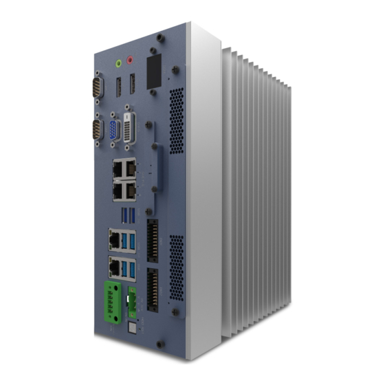
Page 22: I/O Layout
Eagle Eyes-AIHD User Manual 3.1 I/O Layout Front I/O ① System FAN (2 fans) ② DDM (Dynamic Display Module) ③ RTC Battery ④ SIM sockets (3 sockets) ⑤ GPIO or Isolated DI & DO (2 connectors) ⑥ Mic-In ⑦ Line-Out ⑧... - Page 23 Eagle Eyes-AIHD User Manual Top-side IO ㉖ Antenna Hole: 4 holes...
-
Page 24: External I/O
Eagle Eyes-AIHD User Manual External I/O 3.2.1 Power Button with Power LED The Power Button is a non-latched switch with a dual-color LED indicator. It indicates power status: S0, S3, and S5. LED Color Power Status System Status Solid Blue System working Solid Orange S3, S5... -
Page 25: Reset Button
Since there is no specific rule of pin definition for this type of connector, please always confirm the polarity of the power source before plugging it into the Eagle Eyes-AIHD / AIHD-P4E / AIHD-GP4E series if you’re not using the power adapter provided by EFCO. Name Description... -
Page 26: Power Remote & Ignition Control (5-Pin Euro Type Terminal Block)
Eagle Eyes-AIHD User Manual 3.2.5 Power Remote & Ignition Control (5-Pin Euro Type Terminal Block) Name Description IGN- Ignition control Signal- IGN PWR+ Ignition Power V+ Remote + Remote control + Remote GND Remote control Ground PLED+ Power LED+ 3.2.6 Dynamic Display Module (DDM) The Dynamic Display Module (DDM) is a 0.96”... -
Page 27: Displayport Connectors
Eagle Eyes-AIHD User Manual 3.2.7 DisplayPort Connectors The Eagle-Eyes AIHD / AIHD-P4E / AIHD-GP4E series provides two high-resolution DisplayPort (DP) outputs on the I/O panel. It supports video resolutions up to 4096x2304@60Hz. Name Description ML Lane 0 (p) Lane 0 (positive) Ground ML Lane 0 (n) Lane 0 (negative) -
Page 28: Dvi-D Connector
Eagle Eyes-AIHD User Manual 3.2.8 DVI-D Connector The DVI-D connector on the rear panel supports DVI-D display. This connector can send out a DVI signal. The DVI-D output supports up to 1920 x 1200 resolution. The resolution is automatically selected according to the connected display. You will need a DVI-D cable when connecting to a display device. -
Page 29: Vga Connector
Eagle Eyes-AIHD User Manual 3.2.9 VGA Connector The Eagle Eyes-AIHD / AIHD-P4E / AIHD-GP4E series provides a high-resolution VGA video port on the front panel, which supports video resolutions up to 1920x1080. Name Description Red Video (75-ohm, 0.7 V p-p) GREEN Green Video (75-ohm, 0.7 V p-p) BLUE... - Page 30 Eagle Eyes-AIHD User Manual RJ45 Connector 1000 Pin No 10 / 100 Mbps Description Mbps (Optional) BI DA+ Bi-directional pair A + PoE+ BI DA- Bi-directional pair A - PoE+ BI DB+ Bi-directional pair B + PoE- BI DC+ Bi-directional pair C + BI DC- Bi-directional pair C - BI DB-...
-
Page 31: Poe Leds
Intel® XHCI controller, each port supporting up to 5GBs and 5V/0.9A power. They are compliant with Super Speed, High Speed, Full Speed, and Low Speed USB signaling rates. Each port can be powered on/off by the BIOS or an EFCO Application Program. -
Page 32: Audio Line-Out / Mic-In Audio Jacks
The Eagle Eyes-AIHD / AIHD-P4E / AIHD-GP4E series offers 16-bit digital programmable general-purpose input and output (GPIO). Isolated 8-bit DI & 8-bit DO is optional. The GPIO support 3.3V or 5V signal and are configurable by the BIOS or an EFCO Application Program. DI/DO Safety-Related Certifications 2500-V PART NUMBER PACKAGE... - Page 33 Eagle Eyes-AIHD User Manual DI/DO Operation Characteristics Parameter Operation Voltage 5 - 48V DC Source Mode:5 - 48V DC Sink Mode: 5 - 40V DC Input/Output Current 25 uS 100mA Limit Turn On Delay Time 25 uS Source Mode: 15 uS (Max.) Sink Mode: 60uS Turn Off Delay Time...
-
Page 34: Uart Ports
Eagle Eyes-AIHD User Manual 3.2.15 UART Ports The Eagle Eyes-AIHD / AIHD-P4E / AIHD-GP4E series provides two RS-232/422/485 ports and four RS232 ports for communicating with external devices. COM1 - COM6 are located on the I/O panel via 9-pin D-Sub male connectors. - Page 35 Eagle Eyes-AIHD User Manual COM3, COM4 UART Mode RS-232 Description Pin 1 DCD# Data Carrier Detect Pin 2 Receive Data Pin 3 Transmit Data Pin 4 DTR# Data Terminal Ready D-Sub 9 Male Pin 5 System Ground COM3, COM4 Pin 6 Data Set Ready Pin 7 RTS#...
-
Page 36: Usim Slot
Eagle Eyes-AIHD User Manual 3.2.16 USIM Socket The Eagle Eyes-AIHD / AIHD-P4E / AIHD-GP4E series provides three USIM sockets for wireless applications when 3G/4G wireless modules are installed in the full-length Mini PCIe slots. Name Description +5 V DC power supply input (optional use by the card) Reset signal used to reset the card's communications. -
Page 37: Wireless Module Led For Mini Pcie
Eagle Eyes-AIHD User Manual 3.2.17 Wireless module LED for Mini PCIe The Eagle Eyes-AIHD / AIHD-P4E / AIHD-GP4E series supports 3 Mini PCIe slots with 3 USIM socket. It can support any WWAN / WLAN / WPAN Mini PCIe wireless module, such as Wi-Fi, Bluetooth, 3G/4G/LTE, etc. -
Page 38: Antenna Holes
Eagle Eyes-AIHD User Manual 3.2.19 Antenna Holes The Eagle Eyes-AIHD / AIHD-P4E / AIHD-GP4E series system provides four antenna holes on its right-side panel. 1. Proposed SMA connector SPEC: SMA screw length "minimum 10mm." Caution! 2. Proposed Antenna connector SPEC: Antenna screw size "maximum 15mm."... -
Page 39: Internal I/O Functions
Eagle Eyes-AIHD User Manual 3.3 Internal I/O Functions In addition to I/O connectors on the front/rear panel, the Eagle Eyes-AIHD / AIHD-P4E / AIHD-GP4E series provides other useful features via its on-board connectors, such as mSATA socket, Mini PCIe slots. This section describes these internal I/O functions. -
Page 40: Mini Pcie / Msata Socket
Bluetooth, etc. Each full-length Mini PCIe Slot supports Mini PCIe / mSATA mode selected by BIOS setup. Each USIM card slot supports +3.3V Power On/Off control by EFCO Application Program, and one Card Detection LED (WWAN, WLAN & WPAN) on the front panel. - Page 41 Eagle Eyes-AIHD User Manual Top Side Bottom Side PCIe Wake# 3.3V Reserved Reserved 1.5V PCIe CLKREQ# UIM PWR UIM DATA PCIe REFCLK- UIM CLK PCIe REFCLK+ UIM RESET UIM VPP Reserved (UIM C8) Reserved (UIM C4) Reserved PCIe RST# PCIe PERn0/SATA-Tx+ +3.3V SB PCIe PERp0/SATA-TX- +1.5V...
-
Page 42: Internal Usb 2.0 Ports For Usb 2.0 Dongle (Optional)
Eagle Eyes-AIHD User Manual 3.3.3 Internal USB 2.0 Port for a USB 2.0 Dongle The AIHD / AIHD-P4E / AIHD-GP4E series provides one internal USB 2.0 Type A connector. The internal USB port is designed to allow users to attach a protection dongle inside the chassis. - Page 43 Eagle Eyes-AIHD User Manual SATA Data Pinout Name Function Ground Transmit+ Transmit- Ground Receive- Receive+ Ground SATA Power Connector SATA Power Pinout Name Function 12VS DC 12V Ground Ground- DC 5V...
-
Page 44: Chapter 4 Hardware Installation
Eagle Eyes-AIHD User Manual Chapter 4 Hardware Installation This chapter including: LGA1151 CPU Installation and Replacement SO-DIMM Memory Installation Mini PCIe/ mSATA Module Installation 2.5” SATA SSD / HDD Installation IOM Installation Mounting Bracket Installation... -
Page 45: So-Dimm Memory Installation
Eagle Eyes-AIHD User Manual 4.1 SO-DIMM Memory Installation 1. Remove 9 M3*6mm crews from the bottom cover. Install or replace your memory. Note: If only one memory, please install DIMM1 first. -
Page 46: Mini Pcie / Msata Module Installation
Eagle Eyes-AIHD User Manual 3. Replace 9 M3*6mm screws on the bottom cover. 4.3 Mini PCIe / mSATA module installation 1. Remove 9 M3*6mm crews from the bottom cover. - Page 47 Eagle Eyes-AIHD User Manual 2. Install or replace the Mini PCIe / mSATA device in those three slots. 3. Replace 9 M3*6mm screws on the bottom cover.
-
Page 48: Sata Ssd/Hdd Installation
Eagle Eyes-AIHD User Manual 4.4 2.5” SATA SSD / HDD installation 1. Remove 9 M3*6mm crews from the bottom cover. 2. Install 2.5” storage in Disk1, Disk2, or Disk3 areas of the bottom cover inside. - Page 49 Eagle Eyes-AIHD User Manual 3. Connect SATA & SATA power cable to your 2.5" storage, then attach the storage device to the bottom cover by 4 M3*4 screws. 4. Reconnect SATA & SATA power cables, then close the bottom cover. SATA connector SATA power connector...
- Page 50 Eagle Eyes-AIHD User Manual 5. Replace 9 M3*6mm screws on the bottom cover.
-
Page 51: Chapter 5 Function Settings
Eagle Eyes-AIHD User Manual Chapter 5 Function Settings This section includes: Jumper and DIP Switch Clear CMOS Serial Port (UART) RI/+12V/+5V Settings PEG (PCIe x16) Bifurcation PEG (PCIe x 16) Lane Reversal... -
Page 52: Jumper And Dip Switch
Eagle Eyes-AIHD User Manual 5.1 Jumper and DIP switch 5.5.1 Jumper You can configure your board to match the needs of your application by setting jumpers. A jumper is the most straightforward kind of electric switch. It consists of two metal pins and a small metal clip (often protected by a plastic cover) that slides over the pins to connect them. -
Page 53: Clear Cmos (Jp2)
Eagle Eyes-AIHD User Manual The following tables list the function of each of the board’s jumpers and DIP switches. Label Function Note Clear CMOS 3 x 1 header, pitch 2.00 mm Serial Port (COM3) RI/+12V/+5V Setting 3 x 2 header, pitch 2.00 mm JP10 Serial Port (COM3) RI/+12V/+5V Setting 3 x 2 header, pitch 2.00 mm... -
Page 54: Appendix
Eagle Eyes-AIHD User Manual Appendix This section includes: APPENDIX A – Active Video Combinations APPENDIX B – DisplayPort Multi-Stream Transport (MST) Capabilities APPENDIX C – How to use GPIO... -
Page 55: Appendix A: Active Video Display Combinations
Eagle Eyes-AIHD User Manual Appendix A: Active Video Display Combinations The Eagle Eye-AIHD / AIHD-P4E / AIHD-GP4E series support four display connectors – two DP, one DVI-D, and one VGA. The processor supports three streaming independent and simultaneous display combinations of DisplayPort / DVI-D / VGA monitors. -
Page 56: Appendix B: Displayport Multi-Stream Transport (Mst) Capabilities
Eagle Eyes-AIHD User Manual A.2 Display combination Table Attached Display Active Display on Active Display on Active Display Monitor BIOS SETUP Windows on DOS DP1+DP2 DP1 + DP2 DP1+DP2 DP1+DVI-D DP1 + DVI-D DP1+DVI-D DP1+VGA DP1 + VGA DP1+VGA DP1+DP2+DVI-D DP1 + DVI-D DP1+DP2+DVI-D DP1+DP2+VGA... -
Page 57: Appendix C: How To Use Gpio
Eagle Eyes-AIHD User Manual Appendix C: How to use GPIO Functional Description GPIO signals are accessed via a 2.54mm 2x10-pin terminal block, including isolated DI 8 bit, DO 8-bit, DI Com, Power, and GND. DI/DO supports NPN (Sink) and PNPO (Source) mode. DI mode is selected by an external H/W connection. -
Page 58: Pin Definition
Eagle Eyes-AIHD User Manual Pin Definition Description Description Isolated DI bit0 Isolated DO bit0 Isolated DI bit1 Isolated DO bit1 Isolated DI bit2 Isolated DO bit2 Isolated DI bit3 Isolated DO bit3 Isolated DI bit4 Isolated DO bit4 Isolated DI bit5 Isolated DO bit5 Isolated DI bit6 Isolated DO bit6... -
Page 59: Isolation Digital Output Connection Method
Eagle Eyes-AIHD User Manual Digital Input Source Mode Connection Method Pin 9 digital input COM pin connection to V-. Input pin (Pins 1-8) control by V+. 5-48V Isolation Digital Output Connection Method Digital Output Sink Mode Connection Method Digital Input Sink Mode Internal Circurt Current input to system, Control Low status...
Need help?
Do you have a question about the Eagle Eye-AIHD Series and is the answer not in the manual?
Questions and answers