
Related Manuals for WAGO PFC100


Summary of Contents for WAGO PFC100
- Page 1 Manual WAGO-I/O-SYSTEM 750 750-8100 PFC100; 2ETH; ECO Controller PFC100; 2 x ETHERNET; ECO Version 1.6.0, valid from FW Version 03.02.02(14)
- Page 2 We wish to point out that the software and hardware terms as well as the trademarks of companies used and/or mentioned in the present manual are generally protected by trademark or patent. WAGO is a registered trademark of WAGO Verwaltungsgesellschaft mbH. Manual Version 1.6.0, valid from FW Version 03.02.02(14)
-
Page 3: Table Of Contents
WAGO-I/O-SYSTEM 750 Table of Contents 750-8100 PFC100; 2ETH; ECO Table of Contents Notes about this Documentation ............12 Validity of this Documentation............... 12 Copyright ....................12 Property rights ..................13 Symbols ....................14 Number Notation .................. 16 Font Conventions ................. 16 Important Notes .................. - Page 4 Table of Contents WAGO-I/O-SYSTEM 750 750-8100 PFC100; 2ETH; ECO 3.10 Standards and Guidelines ..............47 Function Description ................48 Network ....................48 4.1.1 Interface Configuration ..............48 4.1.1.1 Operation in Switch Mode............48 4.1.1.2 Operation with Separate Network Interfaces........ 48 4.1.2...
-
Page 5: Table Of Contents
Assigning an IP Address using DHCP ..........81 Changing an IP Address Using the “CBM” Configuration Tool and a 7.3.2 Terminal Program ................82 Changing an IP Address using “WAGO Ethernet Settings” ....85 7.3.3 7.3.4 Setting the IP Address with the Address Selection Switch ....87 7.3.5... - Page 6 Table of Contents WAGO-I/O-SYSTEM 750 750-8100 PFC100; 2ETH; ECO “Global MAC Address Filter State” Group ......119 7.8.1.12.1 “MAC Address Filter State Xn” Group ........120 7.8.1.12.2 “MAC Address Filter Whitelist” Group ........120 7.8.1.12.3 “Configuration of User Filter” Page ..........121 7.8.1.13...
-
Page 7: Table Of Contents
WAGO-I/O-SYSTEM 750 Table of Contents 750-8100 PFC100; 2ETH; ECO “TFTP Server” Page ..............143 7.8.1.28 “TFTP Server” Group ............143 7.8.1.28.1 “DHCP Configuration” Page ............144 7.8.1.29 “DHCP Configuration Xn” Group ........... 144 7.8.1.29.1 “Configuration of DNS Service” Page ........145 7.8.1.30... - Page 8 Table of Contents WAGO-I/O-SYSTEM 750 750-8100 PFC100; 2ETH; ECO “PLC Runtime” > “WebVisu” Submenu........174 7.8.2.3.6 “Networking” Menu ..............175 7.8.2.4 “Networking” > “Host/Domain Name” Submenu ....175 7.8.2.4.1 “Host/Domain Name” > “Hostname” Submenu ...... 176 7.8.2.4.2 “Host/Domain Name” > “Domain Name” Submenu ....176 7.8.2.4.3...
-
Page 9: Table Of Contents
“SNMP” > “SNMP v1/v2c Trap Receiver Configuration” 7.8.2.12.3 Submenu ................211 “SNMP” > “SNMP v3 Configuration” Submenu...... 212 7.8.2.12.4 “SNMP” > “(Secure)SNMP firewalling” Submenu ....213 7.8.2.12.5 Configuration using “WAGO Ethernet Settings”......214 7.8.3 7.8.3.1 Identification Tab ............... 216 7.8.3.2 Network Tab ................217 7.8.3.3 PLC Tab .................. - Page 10 Table of Contents WAGO-I/O-SYSTEM 750 750-8100 PFC100; 2ETH; ECO 10.1.1 Fieldbus/System Indicating Elements ..........236 10.2 Diagnostics Messages via Flashing Sequences ......... 240 10.2.1 Flashing Sequences ..............240 10.2.2 Example of a Diagnostics Message Indicated by a Flashing Sequence ..................242 10.2.3...
- Page 11 WAGO-I/O-SYSTEM 750 Table of Contents 750-8100 PFC100; 2ETH; ECO 15.1.2.4 2 Channel Digital Input Modules with Diagnostics and Input Process Data ................277 15.1.2.5 4 Channel Digital Output Modules ..........278 15.1.2.6 4 Channel Digital Output Modules with Diagnostics and Input Process Data ................
-
Page 12: Notes About This Documentation
In addition, ensure that any supplement to this documentation is included, if necessary. Validity of this Documentation This documentation is only applicable to the “PFC100; 2ETH; ECO” controller (750-8100). This documentation is only applicable from FW Version 03.02.02(14). -
Page 13: Property Rights
WAGO-I/O-SYSTEM 750 Notes about this Documentation 750-8100 PFC100; 2ETH; ECO Property rights Third-party trademarks are used in this documentation. This section contains the trademarks used. The “®” and “TM” symbols are omitted hereinafter. • ® ® Adobe and Acrobat are registered trademarks of Adobe Systems Inc. -
Page 14: Symbols
Notes about this Documentation WAGO-I/O-SYSTEM 750 750-8100 PFC100; 2ETH; ECO Symbols Personal Injury! Indicates a high-risk, imminently hazardous situation which, if not avoided, will result in death or serious injury. Personal Injury Caused by Electric Current! Indicates a high-risk, imminently hazardous situation which, if not avoided, will result in death or serious injury. - Page 15 WAGO-I/O-SYSTEM 750 Notes about this Documentation 750-8100 PFC100; 2ETH; ECO Additional Information: Refers to additional information which is not an integral part of this documentation (e.g., the Internet). Manual Version 1.6.0, valid from FW Version 03.02.02(14)
-
Page 16: Number Notation
Notes about this Documentation WAGO-I/O-SYSTEM 750 750-8100 PFC100; 2ETH; ECO Number Notation Table 1: Number Notation Number Code Example Note Decimal Normal notation Hexadecimal 0x64 C notation Binary '100' In quotation marks, nibble separated '0110.0100' with dots (.) Font Conventions... -
Page 17: Important Notes
2.1.1 Subject to Changes WAGO Kontakttechnik GmbH & Co. KG reserves the right to provide for any alterations or modifications. WAGO Kontakttechnik GmbH & Co. KG owns all rights arising from the granting of patents or from the legal protection of utility patents. -
Page 18: Technical Condition Of Specified Devices
These modules contain no parts that can be serviced or repaired by the user. The following actions will result in the exclusion of liability on the part of WAGO Kontakttechnik GmbH & Co. KG: •... -
Page 19: Safety Advice (Precautions)
WAGO-I/O-SYSTEM 750 Important Notes 750-8100 PFC100; 2ETH; ECO Safety Advice (Precautions) For installing and operating purposes of the relevant device to your system the following safety precautions shall be observed: Do not work on devices while energized! All power sources to the device shall be switched off prior to performing any installation, repair or maintenance work. - Page 20 Important Notes WAGO-I/O-SYSTEM 750 750-8100 PFC100; 2ETH; ECO Do not use in telecommunication circuits! Only use devices equipped with ETHERNET or RJ-45 connectors in LANs. Never connect these devices with telecommunication networks. Ensure proper contact with the DIN-rail! Proper electrical contact between the DIN-rail and device is necessary to maintain the EMC characteristics and function of the device.
- Page 21 WAGO-I/O-SYSTEM 750 Important Notes 750-8100 PFC100; 2ETH; ECO Avoid electrostatic discharge! The devices are equipped with electronic components that may be destroyed by electrostatic discharge when touched. Please observe the safety precautions against electrostatic discharge per DIN EN 61340-5-1/-3. When handling the devices, please ensure that environmental factors (personnel, work space and packaging) are properly grounded.
-
Page 22: Licensing Terms Of The Software Package Used
They can be accessed via the WBM page “Legal Information” > “Open Source Software.” You can obtain the source code with licensing terms of the open-source software from WAGO Kontakttechnik GmbH & Co. KG on request. Send your request to with the subject “Controller Board Support Package.” support@wago.com... - Page 23 WAGO-I/O-SYSTEM 750 Important Notes 750-8100 PFC100; 2ETH; ECO performance of your control system. Use encryption methods to protect your data and observe the information provided by the Federal Office for Information Security – “Cloud: Risks and Security Tips”. Observe comparable publications of the competent, public institutions of your country.
-
Page 24: Device Description
750-8100 PFC100; 2ETH; ECO Device Description The controller 750-8100(PFC100; 2ETH; ECO) is an automation device that can perform control tasks of a PLC. It is suitable for mounting on a DIN rail and stands out on account of its various interfaces. - Page 25 WAGO-I/O-SYSTEM 750 Device Description 750-8100 PFC100; 2ETH; ECO In the controller, all input signals from the sensors are combined. After connecting the controller, all of the I/O modules on the bus node are detected and a local process image is created from these. Analog and specialty module data is sent via words and/or bytes;...
- Page 26 Only use recommended memory cards! Use only the microSD memory card available from WAGO (item No. 758- 879/000-3102) as it is suitable for industrial applications subjected to environmental extremes and for use in this device.
-
Page 27: View
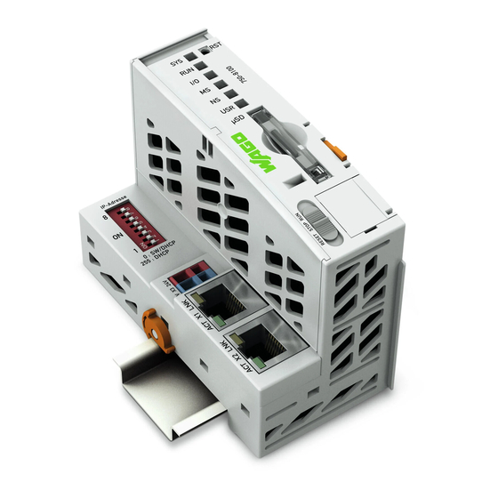
WAGO-I/O-SYSTEM 750 Device Description 750-8100 PFC100; 2ETH; ECO View Figure 1: View Table 3: Legend for Figure “View” Item Description See section Marking options (Mini WSB) “Connectors” > “Data Data contacts Contacts/Local Bus” “Slot for Memory Card” Slot for memory card “Mounting”... - Page 28 Device Description WAGO-I/O-SYSTEM 750 750-8100 PFC100; 2ETH; ECO “Operating Elements” > Address selection switch “Address Selection Switch” “Display Elements” > LED indicators – system “Fieldbus/System Indicating Elements” “Operating Elements” > Reset button (in hole) “Reset Button” Manual Version 1.6.0, valid from FW Version 03.02.02(14)
-
Page 29: Labeling
WAGO-I/O-SYSTEM 750 Device Description 750-8100 PFC100; 2ETH; ECO Labeling The front labeling includes: Device designation Name of the display elements, connections and control elements Serial number with hardware and firmware version The side labeling includes: Manufacturer's identification Connector pin assignment... -
Page 30: Connectors
Device Description WAGO-I/O-SYSTEM 750 750-8100 PFC100; 2ETH; ECO Connectors 3.3.1 Data Contacts/Local Bus Do not place the I/O modules on the gold spring contacts! Do not place the I/O modules on the gold spring contacts in order to avoid soiling... -
Page 31: Service Interface
750-8100 PFC100; 2ETH; ECO 3.3.2 Service Interface The service interface is located behind the flap. The Service interface is used for communication with WAGO-I/O-CHECK and “WAGO Ethernet Settings”. Figure 4: Service Interface (Closed and Open Flap) Table 4: Service Interface... -
Page 32: Network Connectors
Device Description WAGO-I/O-SYSTEM 750 750-8100 PFC100; 2ETH; ECO 3.3.3 Network Connectors Figure 5: Network Connections – X1, X2 Table 5: Legend for Figure “Network Connections – X1, X2” Contact Signal Description TD + Transmit Data + TD − Transmit Data −... -
Page 33: Cage Clamp
WAGO-I/O-SYSTEM 750 Device Description 750-8100 PFC100; 2ETH; ECO ® 3.3.4 CAGE CLAMP Connectors ® Figure 6: CAGE CLAMP Connections (X3) Table 6: Legend for Figure “CAGE CLAMP ® Connections (X3)” Position Designation Description 24 V System power supply voltage +24 V... -
Page 34: Display Elements
PLC program status Orange/Off Red/Green/ Local bus status Orange/Off Red/Green/ Module status Orange/Off Red/Green/ Without function Orange/Off User LED, programmable using function Red/Green/ blocks from the WAGO libraries to control the Orange/Off LEDs Manual Version 1.6.0, valid from FW Version 03.02.02(14) -
Page 35: Memory Card Indicating Elements
WAGO-I/O-SYSTEM 750 Device Description 750-8100 PFC100; 2ETH; ECO 3.4.2 Memory Card Indicating Elements Figure 8: Indicating Elements, Memory Card Slot Table 8: Legend for Figure “Indicating Elements, Memory Card Slot” Description Color Description µSD Yellow/Off Memory card status Manual Version 1.6.0, valid from FW Version 03.02.02(14) -
Page 36: Network Indicating Elements
Device Description WAGO-I/O-SYSTEM 750 750-8100 PFC100; 2ETH; ECO 3.4.3 Network Indicating Elements Figure 9: Indicating Elements, RJ-45 Jacks Table 9: Legend for Figure “Indicating Elements, RJ-45 Jacks” Designation Color Description Green/Off ETHERNET connection status Yellow/Off ETHERNET data exchange Manual Version 1.6.0, valid from FW Version 03.02.02(14) -
Page 37: Operating Elements
WAGO-I/O-SYSTEM 750 Device Description 750-8100 PFC100; 2ETH; ECO Operating Elements 3.5.1 Address Selection Switch Figure 10: Address Selection Switch (here setting “0”) Table 10: Significance of the Address Values of the Address Selection Switch Address value Explanation The IP parameters are configured via the settings in the Web- Based Management (WBM), Console-Based Management (CBM) or by the factory settings. -
Page 38: Operating Mode Switch
Device Description WAGO-I/O-SYSTEM 750 750-8100 PFC100; 2ETH; ECO 3.5.2 Operating Mode Switch Figure 11: Mode Selector Switch </dg_ Table 11: Mode Selector Switch Position Actuation Function Normal operation Latching e!RUNTIME applications running. Stop STOP Latching All e!RUNTIME applications have stopped. -
Page 39: Reset Button
WAGO-I/O-SYSTEM 750 Device Description 750-8100 PFC100; 2ETH; ECO 3.5.3 Reset Button Figure 12: Reset Button The Reset button is installed behind drilling to prevent operating errors. It is a shortstroke button with a low actuating force of 1.1 N … 2.1 N (110 gf … 210 gf). -
Page 40: Slot For Memory Card
Only use recommended memory cards! Use only the microSD memory card available from WAGO (item No. 758- 879/000-3102) as it is suitable for industrial applications subjected to environmental extremes and for use in this device. -
Page 41: Schematic Diagram
WAGO-I/O-SYSTEM 750 Device Description 750-8100 PFC100; 2ETH; ECO Schematic Diagram Figure 14: Schematic switching diagram Manual Version 1.6.0, valid from FW Version 03.02.02(14) -
Page 42: Technical Data
Device Description WAGO-I/O-SYSTEM 750 750-8100 PFC100; 2ETH; ECO Technical Data 3.8.1 Mechanical Data Table 12: Technical Data – Mechanical Data Width 50 mm Height (from upper edge of DIN 35 rail) 65 mm Length 100 mm Weight 114 g 3.8.2 System Data Table 13: Technical Data –... -
Page 43: Clock
WAGO-I/O-SYSTEM 750 Device Description 750-8100 PFC100; 2ETH; ECO 3.8.4 Clock </dg_ Table 15: Technical Data – Clock Drift - system clock (25 °C) 20 ppm Drift - RTC (25 °C) 3 ppm Buffer time RTC (25 °C) 7 days 3.8.5 Programming Table 16: Technical Data –... -
Page 44: Connection Type
Device Description WAGO-I/O-SYSTEM 750 750-8100 PFC100; 2ETH; ECO 3.8.8 Connection Type Table 19: Technical Data – Field Wiring ® Wire connection CAGE CLAMP 0.08 mm² … 2.5 mm², AWG 28 … 14 Cross section 8 mm … 9 mm / 0.33 in Stripped lengths Table 20: Technical Data –... -
Page 45: Approvals
Approvals More information about approvals. Detailed references to the approvals are listed in the document “Overview Approvals WAGO I/O SYSTEM 750”, which you can find via the internet under: DOWNLOADS Documentation System Description. www.wago.com The following approvals have been granted to the “PFC100; 2ETH; ECO”... - Page 46 Device Description WAGO-I/O-SYSTEM 750 750-8100 PFC100; 2ETH; ECO For more information about the ship approvals: Note the “Supplementary Power Supply Regulations” section for the ship approvals. Manual Version 1.6.0, valid from FW Version 03.02.02(14)
-
Page 47: Standards And Guidelines
WAGO-I/O-SYSTEM 750 Device Description 750-8100 PFC100; 2ETH; ECO 3.10 Standards and Guidelines The “PFC100; 2ETH; ECO” controller (750-8100) fulfills the following EMC standards: EMC CE-Immunity to interference EN 61000-6-2 EMC CE-Emission of interference EN 61000-6-3 Manual Version 1.6.0, valid from FW Version 03.02.02(14) -
Page 48: Function Description
Function Description WAGO-I/O-SYSTEM 750 750-8100 PFC100; 2ETH; ECO Function Description </dg_ Network 4.1.1 Interface Configuration The ETHERNET X1 and X2 interfaces of the controller are connected with an internal 3-port switch, in which the third port is connected to the CPU. -
Page 49: Network Security
WAGO-I/O-SYSTEM 750 Function Description 750-8100 PFC100; 2ETH; ECO 4.1.2 Network Security 4.1.2.1 Users and Passwords Several groups of users are provided in the controller which can be used for various services. Default passwords are set for all users. We strongly recommend changing these... -
Page 50: Wbm User Group
Function Description WAGO-I/O-SYSTEM 750 750-8100 PFC100; 2ETH; ECO 4.1.2.1.2 WBM User Group WBM has its own user administration system. The users in this system are isolated from the other user groups in the system for security reasons. Detailed information about this is given in the Section “WBM User Administration”. -
Page 51: Web Protocols For Wbm Access
WAGO-I/O-SYSTEM 750 Function Description 750-8100 PFC100; 2ETH; ECO 4.1.2.2 Web Protocols for WBM Access The HTTP and HTTPS web protocols can be used to access the WBM pages for the controller. HTTPS is preferred because it uses the SSL/TLS protocol. The... - Page 52 Function Description WAGO-I/O-SYSTEM 750 750-8100 PFC100; 2ETH; ECO BSI Guidelines on Migration to TLS 1.2 The German Federal Office for Information Security guidelines on migration to TLS 1.2 contain “compatibility matrices” that show what software is comparable with TLS 1.2.
-
Page 53: Root Certificates
WAGO-I/O-SYSTEM 750 Function Description 750-8100 PFC100; 2ETH; ECO 4.1.2.3 Root Certificates For communication encrypted with TLS, root certificates are used to verify the authenticity of the communication partner. A root certificate, which is signed by a certificate authority, serves to verify the validity of all certificates issued by this certificate authority. -
Page 54: Network Configuration
Function Description WAGO-I/O-SYSTEM 750 750-8100 PFC100; 2ETH; ECO </dg_ 4.1.3 Network Configuration 4.1.3.1 Host Name/Domain Name Without a host name configuration, the controller is assigned a default name which includes the last three values of the controller's MAC address, e.g., “PFCx00-A1A2A3.”... - Page 55 WAGO-I/O-SYSTEM 750 Function Description 750-8100 PFC100; 2ETH; ECO and destination mask entries is always selected. The default gateway corresponds to the least specific routing entry. All network data packets such that no specific routing entry exists for their destination address and destination mask are sent to this default gateway.
- Page 56 Function Description WAGO-I/O-SYSTEM 750 750-8100 PFC100; 2ETH; ECO For forwarding network communication through a router, it is necessary to note that corresponding routing entries must be provided not only for the router, but also for the respective endpoints of the communication. The routing entries of the endpoints must ensure that the desired network data packets are sent via the router, both when the connection is established and with the replies.
-
Page 57: Network Services
WAGO-I/O-SYSTEM 750 Function Description 750-8100 PFC100; 2ETH; ECO 4.1.5 Network Services 4.1.5.1 DHCP Client The controller can get network parameters from an external DHCP master via the DHCP Client service. The following parameters can be obtained: • IP address •... -
Page 58: Table 24: List Of Parameters Transmitted Via Dhcp
Function Description WAGO-I/O-SYSTEM 750 750-8100 PFC100; 2ETH; ECO The settings are made, for example, in the WBM via the “DHCP Configuration” page. The DHCP server also passes other parameters in addition to the IP address. The following table shows the complete list. -
Page 59: Dns Server
WAGO-I/O-SYSTEM 750 Function Description 750-8100 PFC100; 2ETH; ECO server must be manually configured. For the controller, the DHCP server service is handled by the program "dnsmasq". ® From a Linux command line, an editor must be used to change the file “/etc/dnsmasq.d/dnsmasq_default.conf”... -
Page 60: Cloud Connectivity Functionality
Function Description WAGO-I/O-SYSTEM 750 750-8100 PFC100; 2ETH; ECO 4.1.6 Cloud Connectivity Functionality With the cloud connectivity functionality and an IEC library, the controller is available as a gateway for Internet-of-Things (IoT) applications. This means the controller can collect the data from all the connected devices, access the Internet via the built-in Ethernet interface or the mobile communications module and send the data to the cloud. -
Page 61: Components Of The Cloud Connectivity Software Package
Observe the necessary data protection and security settings! Before using the cloud connectivity functionality, consult the corresponding handbook and familiarize yourself with data protection and security issues. You will find this in the Downloads area at www.wago.com. 4.1.6.1 Components of the Cloud Connectivity Software Package... -
Page 62: Memory Card Function
750-8100 PFC100; 2ETH; ECO Memory Card Function Only use recommended memory cards! Use only the microSD memory card available from WAGO (item No. 758- 879/000-3102) as it is suitable for industrial applications subjected to environmental extremes and for use in this device. -
Page 63: Data Backup
WAGO-I/O-SYSTEM 750 Function Description 750-8100 PFC100; 2ETH; ECO 4.2.2 Data Backup The controller has a backup function and a restore function. The necessary settings can be made and the functions can be executed via the WBM pages or via the CBM “Backup” and “Restore” menus. -
Page 64: Restore Function
Function Description WAGO-I/O-SYSTEM 750 750-8100 PFC100; 2ETH; ECO The controller has an automatic update function. If this function is activated on a memory card before the data backup and a controller is booted from this memory card, this data is restored automatically on the internal memory of the controller. - Page 65 WAGO-I/O-SYSTEM 750 Function Description 750-8100 PFC100; 2ETH; ECO File size must not exceed the size of the internal drive! Note that the amount of data in the media/sd/copy/ directory must not exceed the total size of the internal drive. Restoration only possible from internal memory! If the device was booted from the memory card, the firmware cannot be restored.
-
Page 66: Inserting A Memory Card During Operation
Function Description WAGO-I/O-SYSTEM 750 750-8100 PFC100; 2ETH; ECO 4.2.3 Inserting a Memory Card during Operation The fieldbus nodes and the PLC program are running. Insert a memory card during ongoing operation. During normal operation, the memory card is incorporated into the file system of the controller as a drive. -
Page 67: Setting The Home Directory For The Runtime System
WAGO-I/O-SYSTEM 750 Function Description 750-8100 PFC100; 2ETH; ECO 4.2.5 Setting the Home Directory for the Runtime System The home directory for the runtime system is located in the controller's internal memory by default. An existing boot project may be saved in the home directory. -
Page 68: Table 26: Loading A Boot Project
Function Description WAGO-I/O-SYSTEM 750 750-8100 PFC100; 2ETH; ECO Table 26: Loading a Boot Project “Home Boot Project Memory Card Directory on Stored in with Boot Boot Project is Memory Card Internal Flash Project Loaded ... Enabled” Memory Inserted Checked No, no boot project exists... -
Page 69: Mounting
WAGO-I/O-SYSTEM 750 Mounting 750-8100 PFC100; 2ETH; ECO Mounting Installation Position Along with horizontal and vertical installation, all other installation positions are allowed. Use an end stop in the case of vertical mounting! In the case of vertical assembly, an end stop has to be mounted as an additional safeguard against slipping. - Page 70 Mounting WAGO-I/O-SYSTEM 750 750-8100 PFC100; 2ETH; ECO Increase the total length using a coupler module for internal data bus extension! You can increase the total length of a fieldbus node by using a 750-628 I/O Module (coupler module for internal data bus extension). For such a configuration, attach a 750-627 I/O Module (end module for internal data bus extension) after the last I/O module of a module assembly.
-
Page 71: Mounting Onto Carrier Rail
WAGO Kontakttechnik GmbH & Co. KG supplies standardized carrier rails that are optimal for use with the I/O system. If other carrier rails are used, then a technical inspection and approval of the rail by WAGO Kontakttechnik GmbH & Co. KG should take place. -
Page 72: Wago Din Rails
Mounting WAGO-I/O-SYSTEM 750 750-8100 PFC100; 2ETH; ECO 5.3.2 WAGO DIN Rails WAGO carrier rails meet the electrical and mechanical requirements shown in the table below. Table 27: WAGO DIN Rails Item No. Description 210-112 35 × 7.5; 1 mm; steel; bluish, tinned, chromed; slotted 210-113 35 ×... -
Page 73: Mounting Sequence
Always plug a bus end module (750-600) onto the end of the fieldbus node! You must always use a bus end module at all fieldbus nodes with WAGO I/O SYSTEM 750 fieldbus couplers or controllers to guarantee proper data transfer. -
Page 74: Inserting Devices
Mounting WAGO-I/O-SYSTEM 750 750-8100 PFC100; 2ETH; ECO Inserting Devices Do not work when devices are energized! High voltage can cause electric shock or burns. Switch off all power to the device prior to performing any installation, repair or maintenance work. -
Page 75: Connect Devices
Do not connect more than one conductor at one single connection! If more than one conductor must be routed to one connection, these must be connected in an up-circuit wiring assembly, for example using WAGO feed- through terminals. ®... -
Page 76: Power Supply Concept
Therefore, you should always dimension the overcurrent protection according to the anticipated power usage. The system and field voltage of the WAGO-I/O-SYSTEMs 750 is supplied on the head stations and bus supply modules. For components that work with extra low voltage, only SELV/PELV voltage sources should be used. -
Page 77: Supplementary Power Supply Regulations
750-8100 PFC100; 2ETH; ECO 6.2.2 Supplementary Power Supply Regulations The WAGO-I/O-SYSTEM 750 can also be used in shipbuilding or offshore and onshore areas of work (e. g. working platforms, loading plants). This is demonstrated by complying with the standards of influential classification companies such as Germanischer Lloyd and Lloyds Register. -
Page 78: Commissioning
Commissioning WAGO-I/O-SYSTEM 750 750-8100 PFC100; 2ETH; ECO Commissioning Switching On the Controller Before switching on the controller ensure that you • have properly installed the controller (see section “Installation”), • have connected all required data cables (see section “Connections”) to the... -
Page 79: Determining The Ip Address Of The Host Pc
WAGO-I/O-SYSTEM 750 Commissioning 750-8100 PFC100; 2ETH; ECO Determining the IP Address of the Host PC To ensure that the host PC can communicate with the controller via ETHERNET, both devices must be located in the same subnet. ® To determine the IP address of the host PC (with the Microsoft Windows operating system) using the MS DOS prompt, proceed as follows: Open the MS DOS prompt window. -
Page 80: Setting An Ip Address
Adapt IP addressing to your specific system structure to ensure that the PC and the controller can communicate with one another using one of the available configuration tools (WBM, WAGO ETHERNET Settings or CBM – see section “Configuration”). Example for incorporating the controller (192.168.2.17) into an existing network: •... -
Page 81: Assigning An Ip Address Using Dhcp
WAGO-I/O-SYSTEM 750 Commissioning 750-8100 PFC100; 2ETH; ECO 7.3.1 Assigning an IP Address using DHCP The Controller can obtain dynamic IP addresses from a server (DHCP/BootP). In contrast to fixed IP addresses, dynamically assigned addresses are not stored permanently. Therefore, a BootP or DHCP server must be available each time the controller is restarted. -
Page 82: Changing An Ip Address Using The "Cbm" Configuration Tool And A Terminal Program
Commissioning WAGO-I/O-SYSTEM 750 750-8100 PFC100; 2ETH; ECO Changing an IP Address Using the “CBM” Configuration 7.3.2 Tool and a Terminal Program You can also assign a new IP address to the ETHERNET interfaces X1 and X2 using the “CBM” configuration tool provided on the Linux ®... -
Page 83: Figure 22: Cbm - Selecting "Networking
WAGO-I/O-SYSTEM 750 Commissioning 750-8100 PFC100; 2ETH; ECO In the Main menu use the keyboard (arrow keys or numeric keypad) to move to and select Networking and then press [Enter]. Figure 22: CBM – Selecting “Networking” In the Networking menu select TCP/IP and press [Enter]. -
Page 84: Figure 25: Cbm - Selecting The Ip Address
Commissioning WAGO-I/O-SYSTEM 750 750-8100 PFC100; 2ETH; ECO In the menu TCP/IP Configuration select IP Address and press [Enter]. Figure 25: CBM – Selecting the IP Address In the menu Change IP Address enter the new IP address and confirm by clicking [OK]. -
Page 85: Changing An Ip Address Using "Wago Ethernet Settings
To configure the controller use at least Version 6.4.1.1 dated 2015-06-29 of “WAGO Ethernet Settings”! You can use WAGO communication cables or WAGO radio adapters or even the IP network for data communication. Switch off the power supply to the controller. -
Page 86: Figure 28: "Wago Ethernet Settings" - "Network" Tab
“WAGO Ethernet Settings” will restart your controller. This action may require about 30 seconds.) You can now close “WAGO Ethernet Settings”, or make other changes directly in the Web-based Management system as required. To do this, click on [Run WBM] at the right in the window. -
Page 87: Setting The Ip Address With The Address Selection Switch
7.3.4 Setting the IP Address with the Address Selection Switch For the “PFC100; 2ETH; ECO” controller (750-8100), you can change the network settings using the address selection switch. The address selection switch is above the X1 and X2 network ports. - Page 88 Commissioning WAGO-I/O-SYSTEM 750 750-8100 PFC100; 2ETH; ECO 255.255.255.000 Netmask setting: 192.168.129.129 IP address setting: 192.168.129.000 Resulting network address: ---.---.---.129 Resulting device address: ---.---.---.203 Address selection switch: 192.168.129.000 Network address after restart: ---.---.---.203 Device address after restart: 192.168.129.203 IP address after restart: 254 address are possible and can be set (1 …...
-
Page 89: Temporarily Setting A Fixed Ip Address
WAGO-I/O-SYSTEM 750 Commissioning 750-8100 PFC100; 2ETH; ECO </dg_ 7.3.5 Temporarily Setting a Fixed IP Address This procedure temporarily sets the IP address for the X1 interface to the fixed address “192.168.1.17”. When the switch is enabled, the fixed address is also used for interface X2. -
Page 90: Testing The Network Connection
Commissioning WAGO-I/O-SYSTEM 750 750-8100 PFC100; 2ETH; ECO Testing the Network Connection Carry out a ping network function to check whether you can reach the controller at the IP address you have assigned in the network. Open the MS DOS prompt window. -
Page 91: Changing Passwords
WAGO-I/O-SYSTEM 750 Commissioning 750-8100 PFC100; 2ETH; ECO Changing Passwords Change standard passwords The standard passwords are documented in these instructions and therefore do not offer adequate protection! Change the passwords to meet your particular needs! To increase security all passwords should contain a combination of lower case letters (a …... -
Page 92: Shutdown/Restart
Commissioning WAGO-I/O-SYSTEM 750 750-8100 PFC100; 2ETH; ECO </dg_ Shutdown/Restart Switch off the power supply to shut down the controller. To perform a controller restart, press the Reset button as described in the Section “Triggering Reset Functions” > “Software Reset (Restart).”... -
Page 93: Initiating Reset Functions
WAGO-I/O-SYSTEM 750 Commissioning 750-8100 PFC100; 2ETH; ECO </dg_ Initiating Reset Functions You can initiate various reset functions using the mode selector switch and the Reset button (RST). 7.7.1 Warm Start Reset All e!RUNTIME applications are reset with a warm start reset. All global data is set to its initialization values. -
Page 94: Configuration
Access via the PLC program CODESYS using the “WagoAppConfigTool.lib” library. • Access via the PC using “WAGO Ethernet Settings” (section “Configuration Using ‘WAGO Ethernet Settings’”). The CBM is basically for the initial configuration and startup of the controller. Therefore, it only provides a subset of the WBM parameters. For example, parameters that cannot be displayed in a terminal window in a reasonable way and are not necessary for initial startup are not displayed. -
Page 95: Configuration Via Web-Based-Management (Wbm)
WAGO-I/O-SYSTEM 750 Commissioning 750-8100 PFC100; 2ETH; ECO 7.8.1 Configuration via Web-Based-Management (WBM) The HTML pages (from here on referred to as “pages”) of the Web-Based Management are used to configure the controller. Proceed as follows to access the WBM using a web browser: Connect the controller to the ETHERNET network via the ETHERNET interface X1. -
Page 96: Wbm User Administration
Commissioning WAGO-I/O-SYSTEM 750 750-8100 PFC100; 2ETH; ECO Some pages of the WBM are accessible only for certain users. They are only displayed if you have logged into the WBM. You can access the login form via the “Login” link. Pages which cannot be accessed with your current user name are already grayed out in the navigation. -
Page 97: Figure 31: Password Reminder
WAGO-I/O-SYSTEM 750 Commissioning 750-8100 PFC100; 2ETH; ECO Figure 31: Password Reminder Table 32: User Settings in the Default State Users Password user user admin wago Observe access rights Users in WBM are authorized exclusively for access to websites. User administration for controller applications is configured separately. - Page 98 Commissioning WAGO-I/O-SYSTEM 750 750-8100 PFC100; 2ETH; ECO Table 33: Access Rights for WBM Pages Navigation WBM page User – Reboot Reboot Controller admin Package Server – Firmware Backup Firmware Backup admin – Firmware Restore Firmware Restore admin – System Partition...
-
Page 99: General Information About The Page
WAGO-I/O-SYSTEM 750 Commissioning 750-8100 PFC100; 2ETH; ECO 7.8.1.2 General Information about the Page Figure 32: WBM Browser Window (Example) The device name is displayed in the header of the browser window. When the user has logged out, a [Login] button is displayed on the right in the header line, when logged in a [Logout] button is displayed. -
Page 100: Figure 33: Wbm Status Information (Example)
100 Commissioning WAGO-I/O-SYSTEM 750 750-8100 PFC100; 2ETH; ECO A status area with the following elements is displayed on the right: Figure 33: WBM Status Information (Example) • WBM status: This indicates whether the WBM is currently communicating with the device in the background. - Page 101 WAGO-I/O-SYSTEM 750 Commissioning 101 750-8100 PFC100; 2ETH; ECO A tooltip containing more detailed information opens as long as the cursor is positioned over an LED. The text that is displayed also contains the message that put the LED into its current status. The time of the message is also shown.
-
Page 102: Status Information" Page
102 Commissioning WAGO-I/O-SYSTEM 750 750-8100 PFC100; 2ETH; ECO “Status Information” Page 7.8.1.3 The following tables explain the parameters listed on this page: 7.8.1.3.1 “Controller Details” Group This group displays the properties of the controller. Table 34: WBM “Status Information” Page – “Controller Details” Group... -
Page 103: Plc Runtime Information" Page
WAGO-I/O-SYSTEM 750 Commissioning 103 750-8100 PFC100; 2ETH; ECO “PLC Runtime Information” Page 7.8.1.4 Information about the enabled runtime system and PLC program created in the programming software is provided on the “PLC Runtime Information” page. 7.8.1.4.1 “PLC Runtime” Group Table 36: WBM “PLC Runtime Information” Page – “PLC Runtime” Group... -
Page 104: General Plc Runtime Configuration" Page
104 Commissioning WAGO-I/O-SYSTEM 750 750-8100 PFC100; 2ETH; ECO “General PLC Runtime Configuration” Page 7.8.1.5 The settings for the boot project created with the programming software are given on the “General PLC Runtime Configuration” page. 7.8.1.5.1 “General PLC Runtime Configuration” Group Table 37: WBM “General PLC Runtime Configuration”... -
Page 105: Plc Webvisu" Page
WAGO-I/O-SYSTEM 750 Commissioning 105 750-8100 PFC100; 2ETH; ECO “PLC WebVisu” Page 7.8.1.6 The settings for the web visualization created in the runtime system are shown on the “PLC WebVisu” page. 7.8.1.6.1 “Webserver Configuration” Group Table 38: WBM “PLC WebVisu” Page – “Webserver Configuration” Group... -
Page 106: Configuration Of Host And Domain Name" Page
106 Commissioning WAGO-I/O-SYSTEM 750 750-8100 PFC100; 2ETH; ECO “Configuration of Host and Domain Name” Page 7.8.1.7 The settings for the general TCP/IP parameters are found on the “Configuration of Host and Domain Name” page. 7.8.1.7.1 “HostName” Group Table 39: WBM “Configuration of Host and Domain Name” Page – “Hostname” Group... -
Page 107: Domain Name" Group
WAGO-I/O-SYSTEM 750 Commissioning 107 750-8100 PFC100; 2ETH; ECO 7.8.1.7.2 “Domain Name” Group Table 40: WBM “Configuration of Host and Domain Name” Page – “Domain Name” Group Parameters Explanation The domain name currently used is displayed. It may differ from the configured domain name if you... -
Page 108: Tcp/Ip Configuration" Page
108 Commissioning WAGO-I/O-SYSTEM 750 750-8100 PFC100; 2ETH; ECO </dg_ “TCP/IP Configuration” Page 7.8.1.8 The TCP/IP settings for the ETHERNET interfaces are shown on the “TCP/IP configuration” page. 7.8.1.8.1 “IP Configuration (Xn)” Group(s) If the switch is enabled, one group (“IP Configuration”) is shown for both connections. -
Page 109: Default Gateway N" Groups
WAGO-I/O-SYSTEM 750 Commissioning 109 750-8100 PFC100; 2ETH; ECO 7.8.1.8.2 “Default Gateway n” Groups You can configure two default gateways. The controller transmits all network data not going to a station on the local network to a default gateway. First the gateway with the lowest metric is addressed. -
Page 110: Dns Server" Group
110 Commissioning WAGO-I/O-SYSTEM 750 750-8100 PFC100; 2ETH; ECO 7.8.1.8.3 “DNS Server” Group Table 43: WBM “TCP/IP Configuration” Page – “DNS Server” Group Parameters Explanation The addresses of the defined DNS servers are Configured: None/ displayed. If no server has been defined, DNS Server n “Configured: None”... -
Page 111: Ethernet Configuration" Page
WAGO-I/O-SYSTEM 750 Commissioning 111 750-8100 PFC100; 2ETH; ECO “Ethernet Configuration” Page 7.8.1.9 The settings for Ethernet TCP/IP are located on the “Ethernet Configuration” page. 7.8.1.9.1 “Switch Configuration” Group Table 44: WBM “Ethernet Configuration” Page – “Switch Configuration” Group Parameter Explanation Enable or disable the switch. -
Page 112: Interface Xn" Groups
112 Commissioning WAGO-I/O-SYSTEM 750 750-8100 PFC100; 2ETH; ECO 7.8.1.9.2 “Interface Xn” Groups One group (“Interface X1” / “Interface X2”) is displayed for each connection. Table 45: WBM “Ethernet Configuration” Page – “Interface Xn” Groups Parameter Explanation Enabled You can enable or disable the interface. -
Page 113: Routing" Page
WAGO-I/O-SYSTEM 750 Commissioning 113 750-8100 PFC100; 2ETH; ECO “Routing” Page 7.8.1.10 On the “Routing” page you can find settings and information on the routing between the network interfaces. 7.8.1.10.1 “General Routing Configuration” Group Table 46: WBM “Routing” Page – “General Routing Configuration” Group... -
Page 114: Static Routes" Group
114 Commissioning WAGO-I/O-SYSTEM 750 750-8100 PFC100; 2ETH; ECO 7.8.1.10.2 “Static Routes” Group Each configured static route has its own area in the display. To maintain compatibility with earlier firmware versions, at least two routing entries always exist. These can be disabled, but not removed. If a route is either removed or disabled, it is no longer entered in the system. -
Page 115: Dynamic Routes" Group
WAGO-I/O-SYSTEM 750 Commissioning 115 750-8100 PFC100; 2ETH; ECO 7.8.1.10.3 “Dynamic Routes” Group All default gateways received via DHCP are displayed here. Default gateways configured via DHCP are given the metric value 10, which means that they are normally used before the statically configured default gateways. -
Page 116: Port Forwarding" Group
116 Commissioning WAGO-I/O-SYSTEM 750 750-8100 PFC100; 2ETH; ECO 7.8.1.10.5 “Port Forwarding” Group Each entry has its own area in the display. Table 49: WBM “Routing” Page – “Port Forwarding” Group Parameter Explanation Specify here whether port forwarding should be used. -
Page 117: General Firewall Configuration" Page
WAGO-I/O-SYSTEM 750 Commissioning 117 750-8100 PFC100; 2ETH; ECO “General Firewall Configuration” Page 7.8.1.11 7.8.1.11.1 “Global Firewall Parameters” Group Table 50: WBM “General Firewall Configuration” Page – “Global Firewall Parameters” Group Parameters Explanation Enables/disables the complete functionality of the firewall. This setting has the highest priority. If the... -
Page 118: Firewall Parameters Interface Xxx" Group
118 Commissioning WAGO-I/O-SYSTEM 750 750-8100 PFC100; 2ETH; ECO 7.8.1.11.2 “Firewall Parameters Interface xxx” Group These settings in this group refer to the configuration of the firewall at IP level. Table 51: WBM “General Firewall Configuration” Page – “Firewall Parameter Interface xxx” Group... -
Page 119: Configuration Of Mac Address Filter" Page
MAC mask: ff:ff:ff:00:00:00 If you enable the default entry, this already allows communication between different WAGO devices in the network. Enable the MAC address filter before activation! Before activating the MAC address filter, you must enter and activate your own MAC address in the “MAC Address Filter Whitelist.”... -
Page 120: Mac Address Filter State Xn" Group
120 Commissioning WAGO-I/O-SYSTEM 750 750-8100 PFC100; 2ETH; ECO 7.8.1.12.2 “MAC Address Filter State Xn” Group Table 53: WBM “Configuration of MAC Address Filter” Page – “MAC Address Filter State Xn” Group Parameters Explanation Enable or disable here the MAC address filter for the Filter enabled specific interface. -
Page 121: Configuration Of User Filter" Page
WAGO-I/O-SYSTEM 750 Commissioning 121 750-8100 PFC100; 2ETH; ECO “Configuration of User Filter” Page 7.8.1.13 7.8.1.13.1 “User Filter” Group Table 55: WBM “Configuration of User Filter” Page – “User Filter” Group Parameters Explanation Count The number of configured user filters is displayed. -
Page 122: Add New User Filter" Group
122 Commissioning WAGO-I/O-SYSTEM 750 750-8100 PFC100; 2ETH; ECO 7.8.1.13.3 “Add New User Filter” Group You can enter 10 filters. You only have to enter values in the fields that are to be set for the filter. At least one value must be entered, all other fields can remain empty. -
Page 123: Configuration Of Time And Date" Page
WAGO-I/O-SYSTEM 750 Commissioning 123 750-8100 PFC100; 2ETH; ECO “Configuration of Time and Date” Page 7.8.1.14 The settings for date and time are shown on the “Configuration of Time and Date” page. 7.8.1.14.1 “Date on Device” Group Table 58: WBM “Configuration of Time and Date” Page – “Date on Device” Group... -
Page 124: Time Zone" Group
124 Commissioning WAGO-I/O-SYSTEM 750 750-8100 PFC100; 2ETH; ECO 7.8.1.14.3 “Time Zone” Group You can specify the appropriate time zone for your location in this group. The total number of possible time zones is over 500. A complete listing would exceed the scope of this documentation. -
Page 125: Tz String" Group
WAGO-I/O-SYSTEM 750 Commissioning 125 750-8100 PFC100; 2ETH; ECO 7.8.1.14.4 “TZ String” Group In this group you can enter a time zone that is not contained in the “Time Zone” selection. If the controller can associate the TZ string entered with a known time zone that had been missing from the “Time Zone”... -
Page 126: Change Password For Selected User" Group
126 Commissioning WAGO-I/O-SYSTEM 750 750-8100 PFC100; 2ETH; ECO </dg_ “Configuration of the Users for the Web-based Management” Page 7.8.1.15 The settings for user administration are shown on this page. 7.8.1.15.1 “Change Password for Selected User” Group Change passwords Default passwords are documented in these instructions and therefore do not offer adequate protection! Change the passwords to meet your particular needs. -
Page 127: Create Bootable Image" Page
WAGO-I/O-SYSTEM 750 Commissioning 127 750-8100 PFC100; 2ETH; ECO </dg_ “Create Bootable Image” Page 7.8.1.16 You can create a bootable image on the “Create Bootable Image” page. 7.8.1.16.1 "Create Bootable Image from Active Partition (<Active Partition>" Group The active partition that boot-up was performed from is displayed in brackets in the heading. -
Page 128: Configuration Of Service Interface" Page
Table 64: WBM “Configuration of Serial Interface RS-232” page – “Assign Owner of Service Interface” Group Parameters Explanation Specify that the service interface is used for the WAGO Service WAGO Service communication or runtime system Communication communication. Specify that the service interface is assigned to the ® Linux Console ®... -
Page 129: Reboot Controller" Page
WAGO-I/O-SYSTEM 750 Commissioning 129 750-8100 PFC100; 2ETH; ECO </dg_ “Reboot Controller” Page 7.8.1.18 The settings for the system reboot are shown on the “Reboot Controller” page. 7.8.1.18.1 “Reboot Controller” Group Click the [Reboot] button to reboot the system. Account for boot-up time! The boot process takes time. -
Page 130: Firmware Backup" Page
130 Commissioning WAGO-I/O-SYSTEM 750 750-8100 PFC100; 2ETH; ECO “Firmware Backup” Page 7.8.1.19 You can find the controller data backup settings on the “Firmware Backup” page. Table 65: “Firmware-Backup” WBM Page Parameters Explanation You can select the data to be backed up here. - Page 131 WAGO-I/O-SYSTEM 750 Commissioning 131 750-8100 PFC100; 2ETH; ECO No backup of the memory card! Backup from the memory card to the internal flash memory is not possible. Account for backup time Generation of backup files can take several minutes. Stop the CODESYS program before you start the backup procedure to help shorten the time required.
-
Page 132: Firmware Restore" Page
132 Commissioning WAGO-I/O-SYSTEM 750 750-8100 PFC100; 2ETH; ECO “Firmware Restore” Page 7.8.1.20 The settings for restoring the controller data are shown on the “Firmware Restore” page. Table 66: “Firmware Restore” WBM Page Parameters Explanation Select the data source for the restore here. - Page 133 WAGO-I/O-SYSTEM 750 Commissioning 133 750-8100 PFC100; 2ETH; ECO Note the firmware version! Restoring the controller operating system (“System” selection) is only permissible and possible if the firmware versions at the backup and restore times are identical. If necessary, skip restoring the controller operating system, or match the firmware version of the controller to the firmware version of the backup time beforehand.
-
Page 134: System Partition" Page
134 Commissioning WAGO-I/O-SYSTEM 750 750-8100 PFC100; 2ETH; ECO </dg_ “System Partition” Page 7.8.1.21 The settings for specifying the partition that the system will be started from are shown on the “System Partition” page. 7.8.1.21.1 “Current Active Partition” Group The partition currently in use is displayed here. -
Page 135: Mass Storage" Page
WAGO-I/O-SYSTEM 750 Commissioning 135 750-8100 PFC100; 2ETH; ECO </dg_ “Mass Storage” Page 7.8.1.22 A group containing information about the storage volume is displayed for each storage volume that is found, along with an additional group for formatting (when this is possible). -
Page 136: Software Uploads" Page
136 Commissioning WAGO-I/O-SYSTEM 750 750-8100 PFC100; 2ETH; ECO </dg_ “Software Uploads” Page 7.8.1.23 The settings for a device update are shown on the “Software Uploads” page. 7.8.1.23.1 “Upload New Software” Group Table 69: WBM “Software Uploads” Page – “Upload New Software” Group... -
Page 137: Configuration Of Network Services" Page
To reduce the risk of cyber attacks and, thus, enhance your cyber security, close all ports and services in the control components (e.g., Port 6626 for WAGO I/O-CHECK, Port 2455 for CODESYS 2 and Port 11740 for e!COCKPIT) not required by your application. -
Page 138: Http" Group
138 Commissioning WAGO-I/O-SYSTEM 750 750-8100 PFC100; 2ETH; ECO 7.8.1.24.4 “HTTP” Group Table 74: WBM “Configuration of Network Services” Page – “HTTP” Group Parameter Explanation Service active Enable/disable the HTTP service here. Click the [Submit] button to apply the changes. The change takes effect immediately. -
Page 139: Opc Ua" Group
WAGO-I/O-SYSTEM 750 Commissioning 139 750-8100 PFC100; 2ETH; ECO 7.8.1.24.7 “OPC UA” Group Table 77: WBM “Configuration of Network Services” Page – “OPC UA” Group Parameter Explanation Service active Enable/disable the OPC UA service here. Click the [Submit] button to apply the changes. The change only takes effect once the controller restarts. -
Page 140: Configuration Of Ntp Client" Page
140 Commissioning WAGO-I/O-SYSTEM 750 750-8100 PFC100; 2ETH; ECO </dg_ “Configuration of NTP Client” Page 7.8.1.25 The settings for the NTP service are shown on the “Configuration of NTP Client” page. 7.8.1.25.1 “NTP Client Configuration” Group Table 78: WBM “Configuration of NTP Client” Page – “NTP Client Configuration” Group... -
Page 141: Configuration Of Plc Runtime Services" Page
WAGO-I/O-SYSTEM 750 Commissioning 141 750-8100 PFC100; 2ETH; ECO “Configuration of PLC Runtime Services” Page 7.8.1.26 The settings for various services of the enabled runtime system are shown on the “Configuration of PLC Runtime Services” page. 7.8.1.26.1 “General Configuration” Group Table 79: WBM “Configuration of PLC Runtime Services” Page – “General Configuration” Group... -
Page 142: Ssh Server Settings" Page
142 Commissioning WAGO-I/O-SYSTEM 750 750-8100 PFC100; 2ETH; ECO “SSH Server Settings” Page 7.8.1.27 The settings for the SSH service are shown on the “SSH Server Settings” page. 7.8.1.27.1 “SSH Server” Group Table 81: WBM “SSH Server Settings” Page – “SSH Server” Group... -
Page 143: Tftp Server" Page
WAGO-I/O-SYSTEM 750 Commissioning 143 750-8100 PFC100; 2ETH; ECO </dg_ “TFTP Server” Page 7.8.1.28 The settings for the TFTP service are shown on the “TFTP Server” page. 7.8.1.28.1 “TFTP Server” Group Table 82: WBM “TFTP Server” Page – “TFTP Server” Group... -
Page 144: Dhcp Configuration" Page
144 Commissioning WAGO-I/O-SYSTEM 750 750-8100 PFC100; 2ETH; ECO “DHCP Configuration” Page 7.8.1.29 The settings for the DHCP service are shown on the “DHCP Configuration” page. 7.8.1.29.1 “DHCP Configuration Xn” Group Table 83: WBM “DHCP Configuration” – “DHCP Configuration Xn” Group... -
Page 145: Configuration Of Dns Service" Page
WAGO-I/O-SYSTEM 750 Commissioning 145 750-8100 PFC100; 2ETH; ECO “Configuration of DNS Service” Page 7.8.1.30 The settings for the DNS service are shown on the “Configuration of DNS Service” page. 7.8.1.30.1 “DNS Service” Group Table 84: WBM “Configuration of DNS Service” Page – “DNS Service” Group... -
Page 146: Modbus Services Configuration" Page
146 Commissioning WAGO-I/O-SYSTEM 750 750-8100 PFC100; 2ETH; ECO “Modbus Services Configuration” Page 7.8.1.31 The settings for various Modbus services are shown on the “Modbus Services Configuration” page. The groups are only visible if the e!RUNTIME system is enabled. Otherwise an information text is displayed. -
Page 147: Configuration Of Cloud Connectivity" Page
You can find a detailed description of the “Cloud Connectivity” software package with a controller and information on PLC programming in Application Note A500920 in the Downloads area at www.wago.com! 7.8.1.32.1 “Software Version” Group Table 87: WBM “Configuration of Cloud Connectivity” Page – “Software Version” Group... -
Page 148: Settings" Group
148 Commissioning WAGO-I/O-SYSTEM 750 750-8100 PFC100; 2ETH; ECO 7.8.1.32.3 “Settings” Group The parameters indicated depend on the cloud platform setting and, if applicable, on other settings in this group. Table 89: WBM “Configuration of Cloud Connectivity” Page – “Settings” Group... - Page 149 WAGO-I/O-SYSTEM 750 Commissioning 149 750-8100 PFC100; 2ETH; ECO Table 89: WBM “Configuration of Cloud Connectivity” Page – “Settings” Group Parameter Explanation Enter the path here to the file encoded in PEM Key file format that contains the private key for cloud service authentication.
- Page 150 150 Commissioning WAGO-I/O-SYSTEM 750 750-8100 PFC100; 2ETH; ECO Click the [Submit] button to apply a change. The changes only take effect after the controller restarts. For this purpose, use the WBM reboot function. Do not shut down the controller too early! The following table shows the dependencies of the selection and input fields for the selected cloud platform.
-
Page 151: Table 90: Dependencies Of The Selection And Input Fields For The Selected Cloud Platform
WAGO-I/O-SYSTEM 750 Commissioning 151 750-8100 PFC100; 2ETH; ECO Table 90: Dependencies of the Selection and Input Fields for the Selected Cloud Platform Data Cloud Platform Protocol Selection or Input Field Service enabled Cloud platform Hostname Group ID > > Device ID Client ID >... - Page 152 152 Commissioning WAGO-I/O-SYSTEM 750 750-8100 PFC100; 2ETH; ECO >: Visible and active; dependent on other settings (>): Visible, but not active; dependent on other settings Manual Version 1.6.0, valid from FW Version 03.02.02(14)
-
Page 153: Configuration Of General Snmp Parameters" Page
WAGO-I/O-SYSTEM 750 Commissioning 153 750-8100 PFC100; 2ETH; ECO “Configuration of General SNMP Parameters” Page 7.8.1.33 The general settings for SNMP are given on the “Configuration of General SNMP Parameters” page. 7.8.1.33.1 “General SNMP Configuration” Group Table 91: WBM “Configuration of General SNMP Parameters” Page – “General SNMP Configuration”... -
Page 154: Configuration Of Snmp V1/V2C Parameters" Page
154 Commissioning WAGO-I/O-SYSTEM 750 750-8100 PFC100; 2ETH; ECO “Configuration of SNMP v1/v2c Parameters” Page 7.8.1.34 The general settings for SNMP v1/v2c are shown on the “Configuration of SNMP v1/v2c Parameters” page. 7.8.1.34.1 “SNMP v1/v2c Manager Configuration” Group Table 92: WBM “Configuration of SNMP v1/v2c Parameters” Page – “SNMP v1/v2c Manager Configuration”... -
Page 155: Trap Receiver N" Group(S)
WAGO-I/O-SYSTEM 750 Commissioning 155 750-8100 PFC100; 2ETH; ECO 7.8.1.34.3 “Trap Receiver n” Group(s) A dedicated group with the following information is displayed for each trap receiver: Table 94: WBM “Configuration of SNMP v1/v2c Parameters” Page – “Trap Receiver n” Group(s) -
Page 156: Configuration Of Snmp V3 Users" Page
156 Commissioning WAGO-I/O-SYSTEM 750 750-8100 PFC100; 2ETH; ECO </dg_ “Configuration of SNMP v3 Users” Page 7.8.1.35 The general settings for SNMP v3 are shown on the “Configuration of SNMP v3 Users” page. 7.8.1.35.1 “Actually Configured v3 Users” Group(s) Table 96: WBM “Configuration of SNMP v3” Page – “Actually Configured v3 Users” Group... -
Page 157: Add New V3 User" Group
WAGO-I/O-SYSTEM 750 Commissioning 157 750-8100 PFC100; 2ETH; ECO 7.8.1.35.3 “Add New v3 User” Group You can enter 10 users. Table 98: WBM “Configuration of SNMP v3 Users” Page – “Add New v3 User” Group Parameters Explanation Enter the user name here. This name must be unique;... -
Page 158: Diagnostic Information" Page
158 Commissioning WAGO-I/O-SYSTEM 750 750-8100 PFC100; 2ETH; ECO </dg_ “Diagnostic Information” Page 7.8.1.36 The settings for displaying diagnostic messages are shown on the “Diagnostic Information” page. Table 99: WBM “Diagnostic Information” Page Parameter Explanation Read all notifications Activate display of all messages. -
Page 159: Configuration Of Openvpn And Ipsec" Page
WAGO-I/O-SYSTEM 750 Commissioning 159 750-8100 PFC100; 2ETH; ECO “Configuration of OpenVPN and IPsec” Page 7.8.1.37 The general settings for OpenVPN and IPsec are shown on the “Configuration of OpenVPN and IPsec” page. 7.8.1.37.1 “OpenVPN” Group Table 100: WBM “Configuration of OpenVPN and IPsec” Page – “OpenVPN” Group... -
Page 160: Certificate Upload" Group
160 Commissioning WAGO-I/O-SYSTEM 750 750-8100 PFC100; 2ETH; ECO To transfer the selected file from the controller to the PC, click [Start Download] button. The changes only take effect after restarting the controller. For this purpose, use the WBM reboot function. Do not shut down the controller too early! 7.8.1.37.3 “Certificate Upload”... -
Page 161: Security Settings" Page
WAGO-I/O-SYSTEM 750 Commissioning 161 750-8100 PFC100; 2ETH; ECO “Security Settings” Page 7.8.1.38 The network security settings are found on the “Security Settings” page. 7.8.1.38.1 “Transport Layer Security Settings” Group Table 105: “Security Settings” WBM Page – “Transport Layer Security Settings” Group... -
Page 162: Advanced Intrusion Detection Environment (Aide) Page
162 Commissioning WAGO-I/O-SYSTEM 750 750-8100 PFC100; 2ETH; ECO “Advanced Intrusion Detection Environment (AIDE) Page” 7.8.1.39 The network security settings are available on the “Advanced Intrusion Detection Environment (AIDE)” page. 7.8.1.39.1 “Run AIDE check at startup” Group Table 106: “Advanced Intrusion Detection Environment (AIDE) WBM page” – “Run AIDE check at startup”... -
Page 163: Open Source Licenses" Page
WAGO-I/O-SYSTEM 750 Commissioning 163 750-8100 PFC100; 2ETH; ECO “Open Source Licenses” Page 7.8.1.40 The licence conditions for the open source software used for the controller are listed in alphabetical order on the “Open Source Licenses” page. Manual Version 1.6.0, valid from FW Version 03.02.02(14) -
Page 164: Wago Licenses" Page
164 Commissioning WAGO-I/O-SYSTEM 750 750-8100 PFC100; 2ETH; ECO “WAGO Licenses” Page 7.8.1.41 The licence conditions for the WAGO software used in the controller are listed on the “WAGO Licenses” page. Manual Version 1.6.0, valid from FW Version 03.02.02(14) -
Page 165: Configuration Via Console-Based-Management-Tool (Cbm) Using A Terminal Program
WAGO-I/O-SYSTEM 750 Commissioning 165 750-8100 PFC100; 2ETH; ECO 7.8.2 Configuration via Console-Based-Management-Tool (CBM) using a Terminal Program The Console-Based Management Tool (CBM) is basically used for the initial configuration and startup of the controller via a terminal program. Therefore, it only provides a subset of the controller parameters. For example, parameters that cannot be displayed in a terminal window in a reasonable way and are not necessary for initial startup are not displayed. -
Page 166: Cbm Menu Structure Overview
166 Commissioning WAGO-I/O-SYSTEM 750 750-8100 PFC100; 2ETH; ECO 7.8.2.1 CBM Menu Structure Overview Table 108: CBM Menu Structure Menu Hierarchy 0. Quit 1. Information 0. Back to Main Menu 1. Controller Details 2. Network Details 2. PLC Runtime 0. Back to Main Menu 1. - Page 167 WAGO-I/O-SYSTEM 750 Commissioning 167 750-8100 PFC100; 2ETH; ECO Table 108: CBM Menu Structure Menu Hierarchy 1. Users 2. Create Image 3. Reboot Controller 7. Package Server 0. Back to Main Menu 1. Firmware Backup 2. Firmware Restore 3. System Partition 8.
- Page 168 168 Commissioning WAGO-I/O-SYSTEM 750 750-8100 PFC100; 2ETH; ECO Do not power cycle the controller after changing any parameters! Some parameter changes require a controller restart for the changes to apply. Saving changes takes time. Do not power cycle the controller to perform a restart, i.e., changes may be lost by shutting down the controller too soon.
-
Page 169: Information" Menu
WAGO-I/O-SYSTEM 750 Commissioning 169 750-8100 PFC100; 2ETH; ECO “Information” Menu 7.8.2.2 This menu contains other submenus with information on the controller and network. Table 109: “Information” Menu Menu Item Explanation 0. Back to … Back to the higher-level menu 1. Controller Details... -
Page 170: Information" > "Network Details" Submenu
170 Commissioning WAGO-I/O-SYSTEM 750 750-8100 PFC100; 2ETH; ECO 7.8.2.2.2 “Information” > “Network Details” Submenu In this submenu, the network and interface properties of the controller are displayed. If the EHERNET interfaces are operated in “Switched” mode, a common table (“X1/X2”) is displayed for both connections. -
Page 171: Plc Runtime" Menu
WAGO-I/O-SYSTEM 750 Commissioning 171 750-8100 PFC100; 2ETH; ECO “PLC Runtime” Menu 7.8.2.3 This menu contains other submenus with information and settings for the runtime system. Table 112: “PLC Runtime” Menu Menu Item Explanation 0. Back to … Back to the higher-level menu Opens a submenu with information on the runtime 1. -
Page 172: Plc Runtime" > "General Configuration" Submenu
172 Commissioning WAGO-I/O-SYSTEM 750 750-8100 PFC100; 2ETH; ECO 7.8.2.3.3 “PLC Runtime” > “General Configuration” Submenu This submenu contains other submenus with general settings for the runtime system. Table 115: “PLC Runtime” > “General Configuration” Submenu Menu Item Explanation 0. Back to …... -
Page 173: Table 117: "Plc Runtime" > "General Configuration" > "Home Dir On Sd Card
WAGO-I/O-SYSTEM 750 Commissioning 173 750-8100 PFC100; 2ETH; ECO 7.8.2.3.5 “General Configuration” > “Home Dir On SD Card” Submenu In this submenu, define if the home directory for the runtime system should be moved to the memory card. Table 117: “PLC Runtime” > “General Configuration” > “Home Dir On SD Card” Submenu... -
Page 174: Plc Runtime" > "Webvisu" Submenu
174 Commissioning WAGO-I/O-SYSTEM 750 750-8100 PFC100; 2ETH; ECO 7.8.2.3.6 “PLC Runtime” > “WebVisu” Submenu This submenu contains information and settings for the Web visualization. Table 118: “PLC Runtime” > “WebVisu” Submenu Menu Item Explanation 0. Back to … Back to the higher-level menu 1. -
Page 175: Networking" Menu
WAGO-I/O-SYSTEM 750 Commissioning 175 750-8100 PFC100; 2ETH; ECO “Networking” Menu 7.8.2.4 This menu contains other submenus with settings for the network configuration. Table 119: “Networking” Menu Parameters Explanation 0. Back to … Back to the higher-level menu Opens a submenu with setting options for the 1. -
Page 176: Host/Domain Name" > "Hostname" Submenu
176 Commissioning WAGO-I/O-SYSTEM 750 750-8100 PFC100; 2ETH; ECO 7.8.2.4.2 “Host/Domain Name” > “Hostname” Submenu In this submenu, you can set the hostname of the controller. Table 121: “Networking” > “Hostname” Submenu Parameters Explanation Enter here the hostname of the controller to be used... -
Page 177: Tcp/Ip" > "Ip Address" Submenu
WAGO-I/O-SYSTEM 750 Commissioning 177 750-8100 PFC100; 2ETH; ECO 7.8.2.4.5 “TCP/IP” > “IP Address” Submenu This submenu contains other submenus with settings for the ETHERNET interfaces. The submenu only appears if the controller is operated in “Separated” mode. If the controller is operated in “Switched” mode, then the “IP Address” > “X1”... -
Page 178: Tcp/Ip" > "Default Gateway" Submenu
178 Commissioning WAGO-I/O-SYSTEM 750 750-8100 PFC100; 2ETH; ECO 7.8.2.4.7 “TCP/IP” > “Default Gateway” Submenu This submenu contains other submenus with settings for the default gateway. Table 126: “Networking” > “TCP/IP” > “Default Gateway” Submenu Menu Item Explanation 0. Back to …... -
Page 179: Tcp/Ip" > "Dns Server" Submenu
WAGO-I/O-SYSTEM 750 Commissioning 179 750-8100 PFC100; 2ETH; ECO 7.8.2.4.9 “TCP/IP” > “DNS Server” Submenu This submenu contains the settings for the DNS server. Table 128: “Networking” > “TCP/IP” > “DNS Server” Submenu Menu Item Submenu Item / Explanation 0. Back to …... -
Page 180: Ethernet" > "Switch Configuration" Submenu
180 Commissioning WAGO-I/O-SYSTEM 750 750-8100 PFC100; 2ETH; ECO 7.8.2.4.11 “Ethernet” > “Switch Configuration” Submenu This submenu contains the settings for the Switch configuration. Table 130: “Networking” > “Ethernet” > “Switch Configuration” Submenu Submenu Submenu Item / Explanation 0. Back to …... -
Page 181: Ethernet Ports" > "Interface Xn" Submenu
WAGO-I/O-SYSTEM 750 Commissioning 181 750-8100 PFC100; 2ETH; ECO 7.8.2.4.13 “Ethernet Ports” > “Interface Xn” Submenu This submenu contains the settings for the selected ETHERNET interface. Table 132: “Networking” > “Ethernet” > “Ethernet Ports” > “Interface Xn” Submenu Submenu Submenu Item / Explanation 0. -
Page 182: Firewall" Menu
182 Commissioning WAGO-I/O-SYSTEM 750 750-8100 PFC100; 2ETH; ECO “Firewall” Menu 7.8.2.5 This menu contains other submenus for the firewall functionality settings. Table 133: “Firewall” Menu Menu Item Explanation 0. Back to … Back to the higher-level menu 1. General Configuration Opens a submenu with general firewall settings 2. -
Page 183: Firewall" > "General Configuration" Submenu
WAGO-I/O-SYSTEM 750 Commissioning 183 750-8100 PFC100; 2ETH; ECO 7.8.2.5.1 “Firewall” > “General Configuration” Submenu This submenu contains the general settings for the firewall. Table 134: “Firewall” > “General Configuration” Submenu Menu Item Submenu Item / Explanation 0. Back to …... -
Page 184: General Configuration" > "Interface Xxx" Submenu
184 Commissioning WAGO-I/O-SYSTEM 750 750-8100 PFC100; 2ETH; ECO 7.8.2.5.2 “General Configuration” > “Interface xxx” Submenu This submenu contains the firewall settings on the IP level for the selected interface. Table 135: “Firewall” > “General Configuration” > “Interface xxx” Submenu Menu Item Submenu Item / Explanation 0. - Page 185 WAGO-I/O-SYSTEM 750 Commissioning 185 750-8100 PFC100; 2ETH; ECO Click [<OK>] to apply the entry. Click [<Abort>] to discard the entry. Manual Version 1.6.0, valid from FW Version 03.02.02(14)
-
Page 186: Firewall" > "Mac Address Filter" Submenu
186 Commissioning WAGO-I/O-SYSTEM 750 750-8100 PFC100; 2ETH; ECO 7.8.2.5.3 “Firewall” > “MAC Address Filter” Submenu This submenu contains the settings for the MAC address filter. Table 136: “Firewall” > “MAC Address Filter” Submenu Menu Item Submenu Item / Explanation 0. Back to …... -
Page 187: Mac Address Filter" > "Mac Address Filter Whitelist" Submenu187
WAGO-I/O-SYSTEM 750 Commissioning 187 750-8100 PFC100; 2ETH; ECO 7.8.2.5.4 “MAC Address Filter” > “MAC address filter whitelist” Submenu This submenu displays all available filter entries. Table 137: “Firewall” > “MAC Address Filter” > “MAC address filter whitelist” Submenu Menu Item Explanation 0. -
Page 188: Firewall" > "User Filter" Submenu
188 Commissioning WAGO-I/O-SYSTEM 750 750-8100 PFC100; 2ETH; ECO 7.8.2.5.6 “Firewall” > “User Filter” Submenu This submenu displays all available filter entries. Table 139: “Firewall” > “User Filter” Submenu Menu Item Explanation 0. Back to … Back to the higher-level menu 1. -
Page 189: User Filter" > "Add New / No (N)" Submenu
WAGO-I/O-SYSTEM 750 Commissioning 189 750-8100 PFC100; 2ETH; ECO 7.8.2.5.7 “User Filter” > “Add New / No (n)” Submenu In this submenu, you can create, change or delete filter entries. Table 140: “Firewall” > “User Filter” > “Add New / No (n)” Submenu... -
Page 190: Clock" Menu
190 Commissioning WAGO-I/O-SYSTEM 750 750-8100 PFC100; 2ETH; ECO “Clock” Menu 7.8.2.6 This menu contains other submenus for the date and time settings. Table 141: “Clock” Menu Menu Item Submenu Item / Explanation 0. Back to … Back to the higher-level menu 1. -
Page 191: Administration" Menu
WAGO-I/O-SYSTEM 750 Commissioning 191 750-8100 PFC100; 2ETH; ECO “Administration” Menu 7.8.2.7 This menu contains settings for controller administration. Table 142: “Administration” Menu Menu Item Submenu Item / Explanation 0. Back to … Back to the higher-level menu Opens a submenu with settings for the user 1. -
Page 192: Administration" > "Users" Submenu
192 Commissioning WAGO-I/O-SYSTEM 750 750-8100 PFC100; 2ETH; ECO “Administration” > “Users” Submenu 7.8.2.7.1 This submenu contains settings for the user passwords. Table 143: “Administration” > “Users” Submenu Menu Item Explanation 0. Back to … Back to the higher-level menu Enter a new password for the “user” user. -
Page 193: Package Server" Menu
WAGO-I/O-SYSTEM 750 Commissioning 193 750-8100 PFC100; 2ETH; ECO “Package Server” Menu 7.8.2.8 This menu contains other submenus with functions for firmware backup and restore, as well as information and setting options for the current system partition. Table 145: “Package Server” Menu... -
Page 194: Firmware Backup" > "Auto Update Feature" Submenu
194 Commissioning WAGO-I/O-SYSTEM 750 750-8100 PFC100; 2ETH; ECO 7.8.2.8.2 “Firmware Backup” > “Auto Update Feature” Submenu This submenu contains a setting option for the Auto Update function. The submenu only appears if the data for the firmware backup has been selected. -
Page 195: Package Server" > "Firmware Restore" Submenu
WAGO-I/O-SYSTEM 750 Commissioning 195 750-8100 PFC100; 2ETH; ECO 7.8.2.8.4 “Package Server” > “Firmware Restore” Submenu This submenu contains a selection option for the restore source drive. In addition to the enabled partition, the current status is displayed. Table 149: “Package Server” > “Firmware Restore” Menu... -
Page 196: Package Server" > "System Partition" Submenu
196 Commissioning WAGO-I/O-SYSTEM 750 750-8100 PFC100; 2ETH; ECO 7.8.2.8.6 “Package Server” > “System Partition” Submenu This submenu contains information and setting options for the current system partition. Table 151: “Package Server” > “System Partition” Submenu Menu Item Explanation 0. Back to …... -
Page 197: Mass Storage" Menu
WAGO-I/O-SYSTEM 750 Commissioning 197 750-8100 PFC100; 2ETH; ECO “Mass Storage” Menu 7.8.2.9 This menu contains information on the internal flash memory and, if inserted, on the external memory card. In addition to the menu item, the status is displayed for the enabled partition. -
Page 198: Software Uploads" Menu
198 Commissioning WAGO-I/O-SYSTEM 750 750-8100 PFC100; 2ETH; ECO “Software Uploads” Menu 7.8.2.10 This menu contains choices and settings for the device update. You can select fieldbus software, program licenses and update scripts, for example, for transfer from a PC to the controller. -
Page 199: Ports And Services" Menu
Opens a submenu with settings for the DHCPD 9. DHCPD service 10. DNS Opens a submenu with settings for the DNS service Opens a submenu with settings for the WAGO-I/O- 11. IOCHECK PORT CHECK port Opens a submenu with settings for the Modbus TCP 12. Modbus TCP... -
Page 200: Ports And Services" > "Telnet" Submenu
200 Commissioning WAGO-I/O-SYSTEM 750 750-8100 PFC100; 2ETH; ECO 7.8.2.11.1 “Ports and Services” > “Telnet” Submenu This submenu contains the settings for the Telnet service. Table 155: “Ports and Services” > “Telnet” Submenu Menu Item Submenu Item / Explanation 0. Back to …... -
Page 201: Ports And Services" > "Ftps" Submenu
WAGO-I/O-SYSTEM 750 Commissioning 201 750-8100 PFC100; 2ETH; ECO 7.8.2.11.3 “Ports and Services” > “FTPS” Submenu This submenu contains the settings for the FTPS service. Table 157: “Ports and Services” > “FTPS” Submenu Menu Item Submenu Item / Explanation 0. Back to …... -
Page 202: Ports And Services" > "Https" Submenu
202 Commissioning WAGO-I/O-SYSTEM 750 750-8100 PFC100; 2ETH; ECO 7.8.2.11.5 “Ports and Services” > “HTTPS” Submenu This submenu contains the settings for the HTTPS service. Table 159: “Ports and Services” > “HTTPS” Submenu Menu Item Submenu Item / Explanation 0. Back to …... -
Page 203: Ports And Services" > "Ssh" Submenu
WAGO-I/O-SYSTEM 750 Commissioning 203 750-8100 PFC100; 2ETH; ECO 7.8.2.11.7 “Ports and Services” > “SSH” Submenu This submenu contains the settings for the SSH service. Table 161: “Ports and Services” > “SSH” Submenu Menu Item Submenu Item / Explanation 0. Back to …... -
Page 204: Ports And Services" > "Dhcpd" Submenu
204 Commissioning WAGO-I/O-SYSTEM 750 750-8100 PFC100; 2ETH; ECO 7.8.2.11.9 “Ports and Services” > “DHCPD” Submenu This submenu contains the settings for the DHCPD service. Table 163: “Ports and Services” > “DHCPD” Submenu Menu Item Explanation 0. Back to … Back to the higher-level menu Opens a submenu with firewall settings for the this 1. -
Page 205: Ports And Services" > "Dns" Submenu
WAGO-I/O-SYSTEM 750 Commissioning 205 750-8100 PFC100; 2ETH; ECO 7.8.2.11.11 “Ports and Services” > “DNS” Submenu This submenu contains the settings for the DNS service. Table 165: “Ports and Services” > “DNS” Submenu Menu Item Submenu Item / Explanation 0. Back to …... -
Page 206: Ports And Services" > "Iocheck Port" Submenu
206 Commissioning WAGO-I/O-SYSTEM 750 750-8100 PFC100; 2ETH; ECO 7.8.2.11.12 “Ports and Services” > “IOCHECK PORT” Submenu This submenu contains settings for the WAGO-I/O-CHECK port. Table 166: “Ports and Services” > “IOCHECK PORT” Submenu Menu Item Submenu Item / Explanation 0. Back to …... -
Page 207: Ports And Services" > "Modbus Udp" Submenu
WAGO-I/O-SYSTEM 750 Commissioning 207 750-8100 PFC100; 2ETH; ECO 7.8.2.11.14 “Ports and Services” > “Modbus UDP” Submenu This submenu contains the settings for the Modbus UDP service. Table 168: “Ports and Services” > “Modbus UDP” Submenu Menu Item Submenu Item / Explanation 0. -
Page 208: Firewall Status" Submenu
208 Commissioning WAGO-I/O-SYSTEM 750 750-8100 PFC100; 2ETH; ECO 7.8.2.11.16 “…” > “Firewall Status” Submenu This submenu contains firewall settings for the selected service. Table 170: “Ports and Services” > “Firewall Status” Submenu Menu Item Submenu Item / Explanation 0. Back to …... -
Page 209: Ports And Services" > "Plc Runtime Services" Submenu
WAGO-I/O-SYSTEM 750 Commissioning 209 750-8100 PFC100; 2ETH; ECO 7.8.2.11.17 “Ports and Services” > “PLC Runtime Services” Submenu This submenu contains the settings for the PLC runtime system services. Table 171: “Ports and Services” > “PLC Runtime Services” Submenu Menu Item Explanation 0. -
Page 210: Snmp" Menu
210 Commissioning WAGO-I/O-SYSTEM 750 750-8100 PFC100; 2ETH; ECO “SNMP” Menu 7.8.2.12 This menu contains other submenus with the SNMP settings. Table 173: “SNMP” Menu Parameters Explanation 0. Back to … Back to the higher-level menu 1. General SNMP Opens a submenu with general SNMP settings Configuration 2. -
Page 211: Snmp" > "Snmp V1/V2C Manager Configuration" Submenu
WAGO-I/O-SYSTEM 750 Commissioning 211 750-8100 PFC100; 2ETH; ECO 7.8.2.12.2 “SNMP” > “SNMP v1/v2c Manager Configuration” Submenu This submenu contains the SNMP v1/v2c Manager settings. Table 175: “SNMP” > “SNMP v1/v2c Manager Configuration” Submenu Parameters Submenu Item / Explanation 0. Back to …... -
Page 212: Snmp" > "Snmp V3 Configuration" Submenu
212 Commissioning WAGO-I/O-SYSTEM 750 750-8100 PFC100; 2ETH; ECO 7.8.2.12.4 “SNMP” > “SNMP v3 Configuration” Submenu This submenu contains settings for SNMP v3. Table 177: “SNMP” > “SNMP v3 Configuration” Submenu Parameters Explanation 0. Back to … Back to the higher-level menu Opens a submenu with information on the selected (n). -
Page 213: Snmp" > "(Secure)Snmp Firewalling" Submenu
WAGO-I/O-SYSTEM 750 Commissioning 213 750-8100 PFC100; 2ETH; ECO 7.8.2.12.5 “SNMP” > “(Secure)SNMP firewalling” Submenu These submenus contain the SNMP firewall settings. Table 178: “SNMP” > “(Secure )SNMP firewalling” Submenu Menu Item Submenu Item / Explanation 0. Back to … Back to the higher-level menu Enable or disable the firewall for the VPN interface and respective service. -
Page 214: Configuration Using "Wago Ethernet Settings
To configure the controller, use at least Version 6.4.1.1 dated 2015-06-29 or newer of “WAGO Ethernet Settings”! You must select the correct COM port after starting “WAGO Ethernet Settings”. Figure 35: “WAGO Ethernet Settings” – Start Screen For this, click “Settings” and then “Communication”. -
Page 215: Figure 36: "Wago Ethernet Settings" - Communication Link
750-8100 PFC100; 2ETH; ECO Figure 36: “WAGO Ethernet Settings” – Communication Link Once you have configured “WAGO Ethernet Settings” and have clicked [Apply], connection to the controller is established automatically. If “WAGO Ethernet Settings” has already been started with the correct parameters, you can establish connection to the controller by clicking [Read]. -
Page 216: Identification Tab
Besides some fixed values — e.g., item No., MAC address and firmware version — the currently used IP address and the configuration method are also shown here. Figure 37: “WAGO Ethernet Settings” – Identification Tab (Example) Manual Version 1.6.0, valid from FW Version 03.02.02(14) -
Page 217: Network Tab
Specify the specific network parameters for static configuration. Restricted setting for default gateways! Only the default gateway 1 can be set via “WAGO Ethernet Settings.” The default gateway 2 can only be set in the WBM! Preferred DNS server, alternative DNS server Enter the IP address (when required) for an accessible DNS server when identifying network names. - Page 218 218 Commissioning WAGO-I/O-SYSTEM 750 750-8100 PFC100; 2ETH; ECO MAC address. This standard value is also used whenever the chosen name in the “Input” column is deleted. Domain name The current domain name is displayed here. This setting can be automatically overwritten with dynamic configurations, e.g., DHCP.
-
Page 219: Plc Tab
WAGO-I/O-SYSTEM 750 Commissioning 219 750-8100 PFC100; 2ETH; ECO 7.8.3.3 PLC Tab Figure 39: “WAGO Ethernet Settings” – Protocol Tab Here you can select the runtime system. Manual Version 1.6.0, valid from FW Version 03.02.02(14) -
Page 220: Status Tab
220 Commissioning WAGO-I/O-SYSTEM 750 750-8100 PFC100; 2ETH; ECO 7.8.3.4 Status Tab Figure 40: “WAGO Ethernet Settings” – Status Tab General information about the controller status is displayed here. Manual Version 1.6.0, valid from FW Version 03.02.02(14) -
Page 221: E!Runtime Runtime Environment
WAGO-I/O-SYSTEM 750 e!RUNTIME Runtime Environment 221 750-8100 PFC100; 2ETH; ECO e!RUNTIME Runtime Environment General Notes Additional Information Information on the installation and startup of e!COCKPIT is provided in the corresponding manual. Information on programming is provided in the CODESYS 3 documentation. -
Page 222: Codesys V3 Priorities
222 e!RUNTIME Runtime Environment WAGO-I/O-SYSTEM 750 750-8100 PFC100; 2ETH; ECO CODESYS V3 Priorities A list of priorities implemented for the controller is provided below as supplementary information to the CODESYS 3 documentation. Table 179: CODESYS V3 Priorities ® Linux Scheduler... -
Page 223: Memory Spaces Under E!Runtime
WAGO-I/O-SYSTEM 750 e!RUNTIME Runtime Environment 223 750-8100 PFC100; 2ETH; ECO Memory Spaces under e!RUNTIME The memory spaces in the controller under e!RUNTIME have the following sizes: • Program and data memory: 10 Mbytes • Input data: 64 kbytes • Output data: 64 kbytes •... -
Page 224: Modbus - E!Runtime
224 Modbus – e!RUNTIME WAGO-I/O-SYSTEM 750 750-8100 PFC100; 2ETH; ECO Modbus – e!RUNTIME Modbus Address Overview Figure 42: Modbus Address Overview Manual Version 1.6.0, valid from FW Version 03.02.02(14) -
Page 225: Modbus Registers
Modbus – e!RUNTIME 225 WAGO-I/O-SYSTEM 750 750-8100 PFC100; 2ETH; ECO Modbus Registers Table 180: WAGO Modbus Registers Modbus Address Data Length Access Description in Words Dec. Hex. Watchdog Configuration Registers 64,000 0xFA00 Watchdog command register 64,001 0xFA01 Watchdog timeout register... - Page 226 Hex. Constants Registers 64,160 0xFAA0 Constant 0x1234 64,161 0xFAA1 Constant 0xAAAA 64,162 0xFAA2 Constant 0x5555 64,250 0xFAFA Live register The WAGO Modbus registers are described in more details in the following sections. Manual Version 1.6.0, valid from FW Version 03.02.02(14)
-
Page 227: Modbus Watchdog
Modbus – e!RUNTIME 227 WAGO-I/O-SYSTEM 750 750-8100 PFC100; 2ETH; ECO 9.2.1 Modbus Watchdog The Modbus watchdog monitors in the Modbus slave the ongoing Modbus communication with the Modbus master. All valid Modbus requests of a Modbus master from all the services supported by the Modbus slave are trigger events (see chapter “Modbus Mapping”). -
Page 228: Figure 44: State Diagram, Simple_Watchdog Operation Mode
228 Modbus – e!RUNTIME WAGO-I/O-SYSTEM 750 750-8100 PFC100; 2ETH; ECO Figure 44: State Diagram, SIMPLE_WATCHDOG Operation Mode The state diagram for the SIMPLE_WATCHDOG operation mode shows that the watchdog is always active as soon as a timeout > 0 is set in the register 0xFA01 (Watchdog Timeout). -
Page 229: Register 0Xfa00 - Watchdog Command
Modbus – e!RUNTIME 229 WAGO-I/O-SYSTEM 750 750-8100 PFC100; 2ETH; ECO Register 0xFA00 – Watchdog Command 9.2.1.1 This register receives commands for the Modbus watchdog. It cannot be read, i.e. it is not possible to read out the last command written. -
Page 230: Register 0Xfa01 - Watchdog Timeout
230 Modbus – e!RUNTIME WAGO-I/O-SYSTEM 750 750-8100 PFC100; 2ETH; ECO Register 0xFA01 – Watchdog Timeout 9.2.1.2 This register contains the value for the watchdog timeout. The step width is 1 ms and the maximum value is 65535 (corresponds to 65.535 s). The default value is 0. -
Page 231: Register 0Xfa03 - Watchdog Config
Modbus – e!RUNTIME 231 WAGO-I/O-SYSTEM 750 750-8100 PFC100; 2ETH; ECO Register 0xFA03 – Watchdog Config 9.2.1.4 This register contains the configuration parameters for the watchdog. The register is organized in bits, see following table. The register can be read and written irrespective of the watchdog state in the SIMPLE_WATCHDOG operation mode. -
Page 232: Modbus Tcp Connection Watchdog Register
232 Modbus – e!RUNTIME WAGO-I/O-SYSTEM 750 750-8100 PFC100; 2ETH; ECO 9.2.1.5 Modbus TCP Connection Watchdog Register The 0xFA04 register contains the time for the Modbus TCP connection watchdog. Time base is 10 ms. This enables the time to be set up to 655350 ms. -
Page 233: Status Registers
Registers 0xFA10–0xFA17 contain information from the electronic nameplate. It is possible to read the entire nameplate or a consecutive portion of it all at once. 9.2.3.1 Order Number The registers 0xFA10–0xFA13 contain the WAGO order number of the controller. Example: 0750-8202/0025-0001. 0xFA10 = 0750, 0xFA11 = 8202,... -
Page 234: Constant Registers
750-8100 PFC100; 2ETH; ECO 9.2.6 Constant Registers Registers 0xFAA0 … 0xFAA2 provide constants based on the “WAGO Modbus Registers” table. It is possible to read all of the constants, or a consecutive portion of them at once. 0xFAA0 = 0x1234,... -
Page 235: Estimating The Modbus Master Cpu Load
Modbus – e!RUNTIME 235 WAGO-I/O-SYSTEM 750 750-8100 PFC100; 2ETH; ECO Estimating the Modbus Master CPU Load Due to the real-time characteristics of the Linux kernel used, many data points can generate many context changes. For a one-off update (transmitting and receiving of a function code), a CPU time of approx. -
Page 236: Diagnostics
236 Diagnostics WAGO-I/O-SYSTEM 750 750-8100 PFC100; 2ETH; ECO Diagnostics 10.1 Operating and Status Messages The following tables contain descriptions of all operating and status messages for the controller which are indicated by LEDs. 10.1.1 Fieldbus/System Indicating Elements Figure 46: Indicating elements for fieldbus/system... -
Page 237: Table 185: Run Led Diagnostics
“STOP” status after IDE. exception (e.g., If the application cannot be started, memory access error) restart the controller. Contact WAGO Support if the error occurs again. Orange/green Load above threshold Try to reduce the load on the system: flashing value 1 Change the CODESYS program. -
Page 238: Table 186: Diagnostics I/O Led
238 Diagnostics WAGO-I/O-SYSTEM 750 750-8100 PFC100; 2ETH; ECO The I/O LED indicates following diagnostics: Table 186: Diagnostics I/O LED Status Explanation Solution Green Data cycle on the local bus, normal operating status. Orange flashing Startup phase; the local Wait until initialization has bus is being initialized. -
Page 239: Table 187: Ms-Led Diagnostics
WAGO-I/O-SYSTEM 750 Diagnostics 239 750-8100 PFC100; 2ETH; ECO The MS LED indicates following diagnostics: Table 187: MS-LED Diagnostics Status Explanation Remedy No error Red flashing A configuration error An explanation of the flashing sequence is given in the section “Diagnostics via (flashing exists. -
Page 240: Diagnostics Messages Via Flashing Sequences
240 Diagnostics WAGO-I/O-SYSTEM 750 750-8100 PFC100; 2ETH; ECO 10.2 Diagnostics Messages via Flashing Sequences 10.2.1 Flashing Sequences A diagnosis (fault/error) is always displayed as three flashing sequences in a cyclic manner: The first flashing sequence (flickering) initiates reporting of the fault/error. -
Page 241: Figure 47: Flashing Sequence Process Diagram
WAGO-I/O-SYSTEM 750 Diagnostics 241 750-8100 PFC100; 2ETH; ECO Figure 47: Flashing Sequence Process Diagram Manual Version 1.6.0, valid from FW Version 03.02.02(14) -
Page 242: Example Of A Diagnostics Message Indicated By A Flashing Sequence
242 Diagnostics WAGO-I/O-SYSTEM 750 750-8100 PFC100; 2ETH; ECO 10.2.2 Example of a Diagnostics Message Indicated by a Flashing Sequence The example below illustrates the representation of a diagnostics message via a flashing sequence. The I/O LED indicates a data error on the local bus. The data error is caused by the removal of an I/O module located at the 6th position of the bus node. -
Page 243: Meaning Of Blink Codes And Procedures For Troubleshooting
This section describes the diagnostics presented as blink codes via the I/O LEDs. If the diagnostics cannot be cleared by the measured specified for them, contact WAGO support. Be ready to explain to them the blink code that is displayed. Phone:... -
Page 244: Table 189: Error Code 1, Explanation Of Blink Codes And Procedures For Troubleshooting
244 Diagnostics WAGO-I/O-SYSTEM 750 750-8100 PFC100; 2ETH; ECO Table 189: Error Code 1, Explanation of Blink Codes and Procedures for Troubleshooting Error Cause Remedy Argument Invalid parameter Switch off the power to the controller checksum for local and replace it. -
Page 245: Table 190: Error Code 2, Explanation Of Blink Codes And Procedures For Troubleshooting
WAGO-I/O-SYSTEM 750 Diagnostics 245 750-8100 PFC100; 2ETH; ECO Table 189: Error Code 1, Explanation of Blink Codes and Procedures for Troubleshooting Error Cause Remedy Argument Error occurred while Switch off the power to the controller writing to the serial and replace it. -
Page 246: Table 191: Error Code 3, Explanation Of Blink Codes And Procedures For Troubleshooting
246 Diagnostics WAGO-I/O-SYSTEM 750 750-8100 PFC100; 2ETH; ECO Table 191: Error Code 3, Explanation of Blink Codes and Procedures for Troubleshooting Error Cause Solution Argument If a power supply module (e.g., 750-602) is connected to the controller, ensure that this module functions properly (see Section “LED Signaling”). -
Page 247: Table 192: Error Code 4, Explanation Of Blink Codes And Procedures For Troubleshooting
WAGO-I/O-SYSTEM 750 Diagnostics 247 750-8100 PFC100; 2ETH; ECO Table 192: Error Code 4, Explanation of Blink Codes and Procedures for Troubleshooting Error Cause Solution Argument Switch off the power to the controller. Maximum permissible Reduce the number of I/O modules number of I/O modules to an acceptable value. -
Page 248: Table 195: Error Code 9, Explanation Of Blink Codes And Procedures For Troubleshooting
248 Diagnostics WAGO-I/O-SYSTEM 750 750-8100 PFC100; 2ETH; ECO Table 195: Error Code 9, Explanation of Blink Codes and Procedures for Troubleshooting Error Cause Remedy Argument Invalid program Malfunction of the program sequence: statement Contact WAGO Support. Malfunction of the program sequence: Stack overflow Contact WAGO Support. -
Page 249: Meaning Of Blink Codes And Procedures For Troubleshooting
This section describes the diagnostics presented as blink codes via the MS LEDs. If the diagnostics cannot be cleared by the measured specified for them, contact WAGO support. Be ready to explain to them the blink code that is displayed. Phone: +49 571 887 44 55 5... -
Page 250: Service
250 Service WAGO-I/O-SYSTEM 750 750-8100 PFC100; 2ETH; ECO Service 11.1 Inserting and Removing the Memory Card </dg_ 11.1.1 Inserting the Memory Card Use an actuating tool or a screwdriver to open the transparent cover flap by flipping it upwards. The point where to position the tool is marked with an arrow. - Page 251 WAGO-I/O-SYSTEM 750 Service 251 750-8100 PFC100; 2ETH; ECO Close the cover flap by flipping it down and pushing it in until it snaps into place. Manual Version 1.6.0, valid from FW Version 03.02.02(14)
-
Page 252: Firmware Changes
Therefore, use only documentation appropriate for the target firmware after an upgrade/downgrade. If you have any questions, feel free to contact our WAGO Support. 11.2.1 Perform Firmware Upgrade Do not switch the controller off! The controller can be damaged by interrupting the upgrade process. -
Page 253: Perform Firmware Downgrade
WAGO-I/O-SYSTEM 750 Service 253 750-8100 PFC100; 2ETH; ECO 11.2.2 Perform Firmware Downgrade Do not switch the controller off! The controller can be damaged by interrupting the downgrade process. Do not switch the controller off during the downgrade process and do not... -
Page 254: Factory Reset
Stored boot projects are deleted, including existing web visualization data. Subsequently installed firmware functions are not overwritten. If you have any questions, contact WAGO Support. The controller is restarted after the factory reset. Proceed as follows to factory reset the controller: Press the Reset button (RST). -
Page 255: Updating Root Certificates
WAGO-I/O-SYSTEM 750 Service 255 750-8100 PFC100; 2ETH; ECO 11.3 Updating Root Certificates If you want to update the root certificates on the controller, proceed as follows: Download the current root CA bundle from https://curl.haxx.se/ca to your Rename the file “ca-certificates.crt.”... -
Page 256: Removal
256 Removal WAGO-I/O-SYSTEM 750 750-8100 PFC100; 2ETH; ECO Removal Risk of injury due to sharp-edged blade contacts! The blade contacts are sharp-edged. Handle the I/O module carefully to prevent injury. Do not touch the blade contacts. 12.1 Removing Devices Do not work when devices are energized! High voltage can cause electric shock or burns. -
Page 257: Disposal
WAGO-I/O-SYSTEM 750 Disposal 257 750-8100 PFC100; 2ETH; ECO Disposal 13.1 Electrical and electronic equipment Electrical and electronic equipment may not be disposed of with household waste. This also applies to products without this symbol. Electrical and electronic equipment contain materials and substances that can be harmful to the environment and health. - Page 258 258 Disposal WAGO-I/O-SYSTEM 750 750-8100 PFC100; 2ETH; ECO • Dispose of packaging of all types that allows a high level of recovery, reuse and recycling. Improper disposal of packaging can be harmful to the environment and wastes valuable resources. Manual...
-
Page 259: Use In Hazardous Environments
Use in Hazardous Environments 259 750-8100 PFC100; 2ETH; ECO Use in Hazardous Environments The WAGO I/O SYSTEM 750 (electrical equipment) is designed for use in Zone 2 hazardous areas and shall be used in accordance with the marking and installation regulations. -
Page 260: Marking Configuration Examples
260 Use in Hazardous Environments WAGO-I/O-SYSTEM 750 750-8100 PFC100; 2ETH; ECO 14.1 Marking Configuration Examples 14.1.1 Marking for Europe According to ATEX and IECEx Figure 50: Marking Example According to ATEX and IECEx Figure 51: Text Detail – Marking Example According to ATEX and IECEx Manual Version 1.6.0, valid from FW Version 03.02.02(14) -
Page 261: Table 198: Description Of Marking Example According To Atex And Iecex
WAGO-I/O-SYSTEM 750 Use in Hazardous Environments 261 750-8100 PFC100; 2ETH; ECO Table 198: Description of Marking Example According to ATEX and IECEx Marking Description TUEV 07 ATEX 554086 X Approving authority resp. certificate numbers IECEx TUN 09.0001 X Dust Equipment group: All except mining... -
Page 262: Figure 52: Marking Example For Approved Ex I I/O Module According To Atex And Iecex
262 Use in Hazardous Environments WAGO-I/O-SYSTEM 750 750-8100 PFC100; 2ETH; ECO Figure 52: Marking Example for Approved Ex i I/O Module According to ATEX and IECEx Figure 53: Text Detail – Marking Example for Approved Ex i I/O Module According to ATEX and... -
Page 263: Table 199: Description Of Marking Example For Approved Ex I I/O Module According To Atex And Iecex
WAGO-I/O-SYSTEM 750 Use in Hazardous Environments 263 750-8100 PFC100; 2ETH; ECO Table 199: Description of Marking Example for Approved Ex i I/O Module According to ATEX and IECEx Marking Description TUEV 12 ATEX 106032 X Approving authority resp. certificate numbers... -
Page 264: Marking For The United States Of America (Nec) And Canada (Cec)264
264 Use in Hazardous Environments WAGO-I/O-SYSTEM 750 750-8100 PFC100; 2ETH; ECO 14.1.2 Marking for the United States of America (NEC) and Canada (CEC) Figure 54: Marking Example According to NEC Figure 55: Text Detail – Marking Example According to NEC 500... -
Page 265: Figure 56: Text Detail - Marking Example For Approved Ex I I/O Module
WAGO-I/O-SYSTEM 750 Use in Hazardous Environments 265 750-8100 PFC100; 2ETH; ECO Figure 56: Text Detail – Marking Example for Approved Ex i I/O Module According to NEC 505 Table 201: Description of Marking Example for Approved Ex i I/O Module According to NEC 505... -
Page 266: Figure 58: Text Detail - Marking Example For Approved Ex I I/O Modules
266 Use in Hazardous Environments WAGO-I/O-SYSTEM 750 750-8100 PFC100; 2ETH; ECO Figure 58: Text Detail – Marking Example for Approved Ex i I/O Modules According to CEC 18 attachment J Table 203: Description of Marking Example for Approved Ex i I/O Modules According to CEC 18... -
Page 267: Installation Regulations
Special Notes including Explosion Protection The following warning notices are to be posted in the immediately proximity of the WAGO I/O SYSTEM 750 (hereinafter “product”): WARNING – DO NOT REMOVE OR REPLACE FUSED WHILE ENERGIZED! WARNING – DO NOT DISCONNECT WHILE ENERGIZED! WARNING –... - Page 268 268 Use in Hazardous Environments WAGO-I/O-SYSTEM 750 750-8100 PFC100; 2ETH; ECO Explosive atmosphere occurring simultaneously with assembly, installation or repair work must be ruled out. Among other things, these include the following activities • Insertion and removal of components •...
-
Page 269: Special Notes Regarding Ansi/Isa Ex
WAGO-I/O-SYSTEM 750 Use in Hazardous Environments 269 750-8100 PFC100; 2ETH; ECO 14.2.2 Special Notes Regarding ANSI/ISA Ex For ANSI/ISA Ex acc. to UL File E198726, the following additional requirements apply: • Use in Class I, Division 2, Group A, B, C, D or non-hazardous areas only •... -
Page 270: Appendix
(with word alignment). The internal mapping method for data greater than one byte conforms to Intel formats. The following section describes the representation for WAGO-I/O SYSTEM 750 (750 and 753 Series) I/O modules in the process image, as well as the configuration of the process values. -
Page 271: Digital Input Modules
WAGO-I/O-SYSTEM 750 Appendix 271 750-8100 PFC100; 2ETH; ECO 15.1.1 Digital Input Modules Digital input modules supply one bit of data per channel to specify the signal state for the corresponding channel. These bits are mapped into the Input Process Image. -
Page 272: Channel Digital Input Module With Diagnostics And Output Process Data
272 Appendix WAGO-I/O-SYSTEM 750 750-8100 PFC100; 2ETH; ECO 15.1.1.4 2 Channel Digital Input Module with Diagnostics and Output Process Data 750-418, 753-418 The digital input module supplies a diagnostic and acknowledge bit for each input channel. If a fault condition occurs, the diagnostic bit is set. After the fault condition is cleared, an acknowledge bit must be set to re-activate the input. -
Page 273: Channel Digital Input Module Namur With Diagnostics And Output Process Data
WAGO-I/O-SYSTEM 750 Appendix 273 750-8100 PFC100; 2ETH; ECO 15.1.1.7 8 Channel Digital Input Module NAMUR with Diagnostics and Output Process Data 750-439 The digital input module NAMUR provides via one logical channel 2 byte for the input and output process image. -
Page 274: Channel Digital Input Module Ptc With Diagnostics And Output Process Data
274 Appendix WAGO-I/O-SYSTEM 750 750-8100 PFC100; 2ETH; ECO 15.1.1.8 8 Channel Digital Input Module PTC with Diagnostics and Output Process Data 750-1425 The digital input module PTC provides via one logical channel 2 byte for the input and output process image. -
Page 275: Channel Digital Input Modules
WAGO-I/O-SYSTEM 750 Appendix 275 750-8100 PFC100; 2ETH; ECO 15.1.2 16 Channel Digital Input Modules 750-1400, -1402, -1405, -1406, -1407 Table 212: 16 Channel Digital Input Modules Input Process Image Input Byte D0 Bit 7 Bit 6 Bit 5 Bit 4... -
Page 276: Digital Output Modules
276 Appendix WAGO-I/O-SYSTEM 750 750-8100 PFC100; 2ETH; ECO 15.1.2.1 Digital Output Modules Digital output modules use one bit of data per channel to control the output of the corresponding channel. These bits are mapped into the Output Process Image. Some digital modules have an additional diagnostic bit per channel in the Input Process Image. -
Page 277: Channel Digital Input Modules With Diagnostics And Input Process Data
WAGO-I/O-SYSTEM 750 Appendix 277 750-8100 PFC100; 2ETH; ECO 15.1.2.4 2 Channel Digital Input Modules with Diagnostics and Input Process Data 750-507 (-508), -522, 753-507 The digital output modules have a diagnostic bit for each output channel. When an output fault condition occurs (i.e., overload, short circuit, or broken wire), a diagnostic bit is set. -
Page 278: Channel Digital Output Modules
278 Appendix WAGO-I/O-SYSTEM 750 750-8100 PFC100; 2ETH; ECO 15.1.2.5 4 Channel Digital Output Modules 750-504, -515, -516, -519, -531, 753-504, -516, -531, -540 Table 217: 4 Channel Digital Output Modules Output Process Image Bit 7 Bit 6 Bit 5 Bit 4... -
Page 279: Channel Digital Output Modules With Diagnostics And Input Process Data
WAGO-I/O-SYSTEM 750 Appendix 279 750-8100 PFC100; 2ETH; ECO 15.1.2.8 8 Channel Digital Output Modules with Diagnostics and Input Process Data 750-537, 753-537 The digital output modules have a diagnostic bit for each output channel. When an output fault condition occurs (i.e., overload, short circuit, or broken wire), a diagnostic bit is set. -
Page 280: Channel Digital Input/Output Modules
280 Appendix WAGO-I/O-SYSTEM 750 750-8100 PFC100; 2ETH; ECO 15.1.2.10 8 Channel Digital Input/Output Modules 750-1502, -1506 Table 222: 8 Channel Digital Input/Output Modules Input Process Image Bit 7 Bit 6 Bit 5 Bit 4 Bit 3 Bit 2 Bit 1... -
Page 281: Analog Input Modules
Information on the structure of control and status bytes For detailed information on the structure of a particular I/O module’s control/status bytes, please refer to that module’s manual. Manuals for each module can be found on the Internet at www.wago.com. 15.1.3.1 1 Channel Analog Input Modules... -
Page 282: Channel Analog Input Modules Hart
The operating mode is set using the WAGO-I / O-CHECK commissioning tool. Manual Version 1.6.0, valid from FW Version 03.02.02(14) -
Page 283: Channel Analog Input Modules
WAGO-I/O-SYSTEM 750 Appendix 283 750-8100 PFC100; 2ETH; ECO Table 225: 2-Channel Analog Input Modules HART Input Process Image Byte Destination Offset Description High Byte Low Byte Measured Value Channel 1 Measured Value Channel 2 Table 226:: 2 Channel Analog Input Modules HART + 6 bytes Mailbox... -
Page 284: Channel Analog Input Modules
284 Appendix WAGO-I/O-SYSTEM 750 750-8100 PFC100; 2ETH; ECO 15.1.3.5 8 Channel Analog Input Modules 750-451, 750-458, 750-496, 750-497 Table 228: 8 Channel Analog Input Modules Input Process Image Byte Destination Offset Description High Byte Low Byte Measured Value Channel 1... -
Page 285: 3-Phase Power Measurement Module
WAGO-I/O-SYSTEM 750 Appendix 285 750-8100 PFC100; 2ETH; ECO 15.1.3.6 3-Phase Power Measurement Module 750-493 The above Analog Input Modules have a total of 9 bytes of user data in both the Input and Output Process Image (6 bytes of data and 3 bytes of control/status). -
Page 286: Table 230: 3-Phase Power Measurement Modules 750-494, -495, (And All Variations)
286 Appendix WAGO-I/O-SYSTEM 750 750-8100 PFC100; 2ETH; ECO 750-494, -495, (and all variations) The 3-Phase Power Measurement Modules 750-494, -495, (and all variations) have a total of 24 bytes of user data in both the Input and Output Process Image (16 bytes of data and 8 bytes of control/status). -
Page 287: Analog Output Modules
Information on the structure of control and status bytes For detailed information on the structure of a particular I/O module’s control/status bytes, please refer to that module’s manual. Manuals for each module can be found on the Internet at www.wago.com. 15.1.4.1 2 Channel Analog Output Modules... -
Page 288: Specialty Modules
750-8100 PFC100; 2ETH; ECO 15.1.5 Specialty Modules WAGO has a host of Specialty I/O modules that perform various functions. With individual modules beside the data bytes also the control/status byte is mapped in the process image. The control/status byte is required for the bidirectional data exchange of the module with the higher-ranking control system. -
Page 289: Table 234: Counter Modules 750-404/000-005, 753-404/000-005
WAGO-I/O-SYSTEM 750 Appendix 289 750-8100 PFC100; 2ETH; ECO 750-404/000-005, 753-404/000-005 The above Counter Modules have a total of 5 bytes of user data in both the Input and Output Process Image (4 bytes of counter data and 1 byte of control/ status). -
Page 290: Table 235: Counter Modules 750-633
290 Appendix WAGO-I/O-SYSTEM 750 750-8100 PFC100; 2ETH; ECO 750-633 The above Counter Module has a total of 5 bytes of user data in both the Input and Output Process Image (4 bytes of counter data and 1 byte of control/ status). -
Page 291: Pulse Width Modules
WAGO-I/O-SYSTEM 750 Appendix 291 750-8100 PFC100; 2ETH; ECO Output Process Image Byte Designation Offset Description High Byte Low Byte Control byte of Counter 1 Counter Setting Value of Counter 1 Control byte of Counter 2 Counter Setting Value of Counter 2 15.1.5.2... -
Page 292: Serial Interface Modules With Standard Data Format
Thus, each Serial Interface Module uses between 8 and 48 bytes in the process image. The sizes of the input and output process images are always the same. The process image sizes are set with the startup tool WAGO-I/O-CHECK. Manual... -
Page 293: Data Exchange Module
WAGO-I/O-SYSTEM 750 Appendix 293 750-8100 PFC100; 2ETH; ECO Table 240: Serial Interface Modules 750-652, 753-652 Input and Output Process Image Process Byte Designation image Offset Description High Byte Low Byte size Control/Status byte Control/Status byte C1/S1 C0/S0 C1/S1 C0/S0 8 bytes …... -
Page 294: Incremental Encoder Interface Modules
294 Appendix WAGO-I/O-SYSTEM 750 750-8100 PFC100; 2ETH; ECO Table 242: SSI Transmitter Interface Modules Input Process Image Byte Designation Offset Description High Byte Low Byte Data bytes 750-630/000-004, -005, -007 In the input process image, SSI transmitter interface modules with status occupy 5 usable bytes, 4 data bytes, and 1 additional status byte. -
Page 295: Table 245: Incremental Encoder Interface Modules 750-634
WAGO-I/O-SYSTEM 750 Appendix 295 750-8100 PFC100; 2ETH; ECO 750-634 The above Incremental Encoder Interface module has 5 bytes of input data (6 bytes in cycle duration measurement mode) and 3 bytes of output data. The following tables illustrate the Input and Output Process Image, which has 4 words mapped into each image. -
Page 296: Dc-Drive Controller
296 Appendix WAGO-I/O-SYSTEM 750 750-8100 PFC100; 2ETH; ECO Digital Pulse Interface module 750-635, 753-635 The above Digital Pulse Interface module has a total of 4 bytes of user data in both the Input and Output Process Image (3 bytes of module data and 1 byte of control/status). -
Page 297: Stepper Controller
WAGO-I/O-SYSTEM 750 Appendix 297 750-8100 PFC100; 2ETH; ECO Output Process Image Byte Designation Offset Description High Byte Low Byte Control byte C1 Control byte C0 Setpoint position Setpoint position (LSB) Setpoint position Setpoint position (MSB) 15.1.5.10 Stepper Controller 750-670, -671, -672 The Stepper controller provides the fieldbus coupler/controller 12 bytes input and output process image via 1 logical channel. -
Page 298: Rtc Module
298 Appendix WAGO-I/O-SYSTEM 750 750-8100 PFC100; 2ETH; ECO 15.1.5.11 RTC Module 750-640 The RTC Module has a total of 6 bytes of user data in both the Input and Output Process Image (4 bytes of module data and 1 byte of control/status and 1 byte ID for command). -
Page 299: Table 251: Dali Multi-Master Module 753-647 In The "Easy" Mode
WAGO-I/O-SYSTEM 750 Appendix 299 750-8100 PFC100; 2ETH; ECO Table 251: DALI Multi-Master Module 753-647 in the "Easy" Mode Input Process Image Byte Designation Offset Note High Byte Low Byte res. Status, activate broadcast Bit 0: 1-/2-button mode Bit 2: Broadcast status ON/OFF Bit 1,3-7: - DA4…DA7... - Page 300 300 Appendix WAGO-I/O-SYSTEM 750 750-8100 PFC100; 2ETH; ECO Output Process Image Byte Designation Offset Note High Byte Low Byte res. Bit 0: Broadcast ON Bit 1: Broadcast OFF Bit 2: (1 button operation): - short: Broadcast ON/OFF - long: Broadcast dimming...
-
Page 301: Table 252: Dali Multi-Master Module 753-647 In The "Full" Mode
WAGO-I/O-SYSTEM 750 Appendix 301 750-8100 PFC100; 2ETH; ECO Table 252: DALI Multi-Master Module 753-647 in the "Full" Mode Input and Output Process Image Byte Designation Offset Note High Byte Low Byte MBX_C/S C0/S0 Mailbox control/status byte control/status byte MBX1 MBX0... -
Page 302: Lon Ftt Module
® The process image of the LON FTT module consists of a control/status byte and 23 bytes of bidirectional communication data that is processed by the WAGO-I/O- PRO function block "LON_01.lib". This function block is essential for the function ®... -
Page 303: Mp Bus Master Module
® ® Bluetooth process data can be found in the documentation for the Bluetooth 750-644 RF Transceiver. The mailbox and the process image sizes are set with the startup tool WAGO- I/O-CHECK. Manual Version 1.6.0, valid from FW Version 03.02.02(14) -
Page 304: Vibration Velocity/Bearing Condition Monitoring Vib I/O
304 Appendix WAGO-I/O-SYSTEM 750 750-8100 PFC100; 2ETH; ECO ® Table 256: Bluetooth RF-Transceiver 750-644 Input and Output Process Image Process Byte Destination image Offset Description High Byte Low Byte size Control/status C0/S0 not used byte 12 bytes … … …... -
Page 305: Knx/Eib/Tp1 Module
WAGO-I/O-SYSTEM 750 Appendix 305 750-8100 PFC100; 2ETH; ECO 15.1.5.18 KNX/EIB/TP1 Module 753-646 The KNX/TP1 module appears in router and device mode with a total of 24-byte user data within the input and output area of the process image, 20 data bytes and 2 control/status bytes. -
Page 306: Table 259: As-Interface Master Module 750-655, 753-655
306 Appendix WAGO-I/O-SYSTEM 750 750-8100 PFC100; 2ETH; ECO Subsequently the mailbox data are mapped, when the mailbox is permanently superimposed (Mode 1). In the operating mode with suppressible mailbox (Mode 2), the mailbox and the cyclical process data are mapped next. -
Page 307: System Modules
WAGO-I/O-SYSTEM 750 Appendix 307 750-8100 PFC100; 2ETH; ECO 15.1.6 System Modules 15.1.6.1 System Modules with Diagnostics 750-606 The modules provide 2 bits of diagnostics in the Input Process Image for monitoring of the internal power supply. Table 260: System Modules with Diagnostics 750-606, -611... -
Page 308: Table 263: Binary Space Module 750-622 (With Behavior Like 2 Channel Digital Input)
308 Appendix WAGO-I/O-SYSTEM 750 750-8100 PFC100; 2ETH; ECO The Binary Space Modules behave alternatively like 2 channel digital input modules or output modules and seize depending upon the selected settings 1, 2, 3 or 4 bits per channel. According to this, 2, 4, 6 or 8 bits are occupied then either in the process input or the process output image. -
Page 309: List Of Figures
Figure 35: “WAGO Ethernet Settings” – Start Screen ........214 Figure 36: “WAGO Ethernet Settings” – Communication Link ......215 Figure 37: “WAGO Ethernet Settings” – Identification Tab (Example) ....216 Figure 38: “WAGO Ethernet Settings” – Network Tab ........217 Figure 39: “WAGO Ethernet Settings”... - Page 310 310 List of Figures WAGO-I/O-SYSTEM 750 750-8100 PFC100; 2ETH; ECO Figure 48: Inserting the Memory Card .............. 250 Figure 49: Release Tab of Controller ..............256 Figure 50: Marking Example According to ATEX and IECEx ......260 Figure 51: Text Detail – Marking Example According to ATEX and IECEx ..260 Figure 52: Marking Example for Approved Ex i I/O Module According to ATEX and IECEx ....................
-
Page 311: List Of Tables
Table 25: Components of the Cloud Connectivity Software Package ....61 Table 26: Loading a Boot Project ...............68 Table 27: WAGO DIN Rails ................72 Table 28: Filter Modules for 24 V Supply ............77 Table 29: Default IP Addresses for ETHERNET Interfaces ........80 Table 30: Network Mask 255.255.255.0 .............80... - Page 312 312 List of Tables WAGO-I/O-SYSTEM 750 750-8100 PFC100; 2ETH; ECO Table 44: WBM “Ethernet Configuration” Page – “Switch Configuration” Group ........................ 111 Table 45: WBM “Ethernet Configuration” Page – “Interface Xn” Groups ... 112 Table 46: WBM “Routing” Page – “General Routing Configuration” Group ..113 Table 47: WBM “Routing”...
- Page 313 WAGO-I/O-SYSTEM 750 List of Tables 313 750-8100 PFC100; 2ETH; ECO Table 79: WBM “Configuration of PLC Runtime Services” Page – “General Configuration” Group ................141 Table 80: WBM “Configuration of CODESYS Services” Page – “e!RUNTIME Webserver” Group................... 141 Table 81: WBM “SSH Server Settings” Page – “SSH Server” Group ....142 Table 82: WBM “TFTP Server”...
- Page 314 314 List of Tables WAGO-I/O-SYSTEM 750 750-8100 PFC100; 2ETH; ECO Table 107: “Advanced Intrusion Detection Environment (AIDE)” WBM page – “Control AIDE and show log” Group ............162 Table 108: CBM Menu Structure ..............166 Table 109: “Information” Menu ................. 169 Table 110: “Information”...
- Page 315 Table 177: “SNMP” > “SNMP v3 Configuration” Submenu ....... 212 Table 178: “SNMP” > “(Secure )SNMP firewalling” Submenu ......213 Table 179: CODESYS V3 Priorities ..............222 Table 180: WAGO Modbus Registers .............. 225 Table 181: Watchdog Commands ..............229 Table 182: Watchdog Status ................230 Table 183: Watchdog Configuration ..............
- Page 316 316 List of Tables WAGO-I/O-SYSTEM 750 750-8100 PFC100; 2ETH; ECO Table 192: Error Code 4, Explanation of Blink Codes and Procedures for Troubleshooting ..................247 Table 193: Error Code 5, Explanation of Blink Codes and Procedures for Troubleshooting ..................247 Table 194: Error Code 7, Explanation of Blink Codes and Procedures for Troubleshooting ..................
- Page 317 WAGO-I/O-SYSTEM 750 List of Tables 317 750-8100 PFC100; 2ETH; ECO Table 226:: 2 Channel Analog Input Modules HART + 6 bytes Mailbox .... 283 Table 227: 4 Channel Analog Input Modules ............ 283 Table 228: 8 Channel Analog Input Modules ............ 284 Table 229: 3-Phase Power Measurement Module ..........
- Page 318 WAGO Kontakttechnik GmbH & Co. KG • Postfach 2880 D - 32385 Minden Hansastraße 27 • D - 32423 Minden +49 571 887 – 0 Phone: +49 571 887 – 844169 Fax: E-Mail: info@wago.com Internet: www.wago.com...
Need help?
Do you have a question about the PFC100 and is the answer not in the manual?
Questions and answers