
Related Manuals for CTC Union ITP-800-8PH24


Summary of Contents for CTC Union ITP-800-8PH24
- Page 1 Quick Installation Guide ITP-800-8PH24 ITP-800-8PHE24 IP56 EN50155 8 x 10/100Base-TX with 8 x PoE+ Ethernet Switch (Hardened) sales@ctcu.com...
- Page 2 T +886-2-26591021 F +886-2-26590237 E sales@ctcu.com H www.ctcu.com To download this QIG, please visit https://www.ctcu.com/en/download.html 2019 CTC Union Technologies Co., LTD. All trademarks are the property of their respective owners. Technical information in this document is subject to change without notice.
-
Page 3: Table Of Contents
Table of Contents Introduction ................... 4 Package List .................. 4 Features ..................4 Specifications ................5 Panel ....................7 PIN Assignment................8 M12 Cable Connector Installation ..........9 LED Indicators ................10 Earth Ground Connection ............11 Wall-Mounting & Din-Rail Installation ........12 Application .................. -
Page 4: Introduction
Introduction ITP-800-8PH(E)24 devices, designed for industrial grade applications, are unmanaged Fast Ethernet PoE+ switches. ITP-800-8PH(E)24 Ethernet switches provide 8 x 10/100Base-TX Fast Ethernet PoE+ ports that utilize M12 connectors to ensure tight and robust connections against environmental disturbances such as vibration and shock. -
Page 5: Specifications
Specifications Interface Connector Type: 8 x M12 D-Code Female Speed: 10/100Base-TX Support Auto Negotiation and Auto MDI/MDI-X Support 802.3x Flow Control Support Half/Full Duplex Store & Forward Data Processing Switch MAC Address Table: 1K ... - Page 6 Dimensions: 67 mm (D) x 71.4 mm (W) x 219.5 mm (H) Installation: Wall mounting & DIN-Rail (Optional accessory) Weight: 715g Environmental Operating Temperature: -10°C~60°C (ITP-800-8PH24), -40°C~75°C (ITP-800- 8PHE24) Storage Temperature: -40°C~85°C Humidity: 5%~95% (Non-condensing) Certifications ...
-
Page 7: Panel
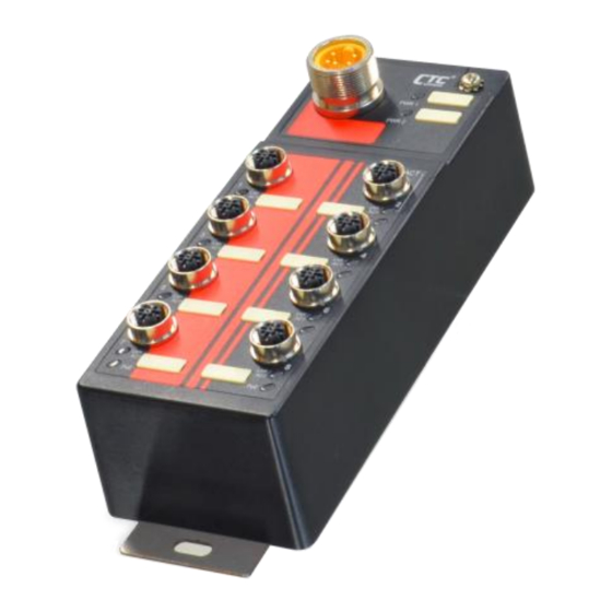
Panel Index Description Wall mounting holes Grounding screw M23 power input port Power port label Power LED M12 Ethernet ports Ethernet port LED PoE LED Ethernet port label Figure 1: Front Panel... -
Page 8: Pin Assignment
PIN Assignment M12 Fast Ethernet Cable Model: CAB-M12DM4-RJ45 M12 Pin No. RJ-45 Pin No. Ethernet Pinout PoE Pinout NOTE: ITP-800-8PH(E)24 is a PSE device that can connect to PDs (Powered Devices) or non-PoE devices. However, it is NOT recommended to connect ITP- 800-8PH(E)24 to another PSE device. -
Page 9: M12 Cable Connector Installation
M12 Cable Connector Installation Before assembling M12 open cable, make sure you have the following M12 cable connector components (Model: M12D-M4 M12 D-Code Male) and open cable at hand. Screw Nut O-Ring Housing Male Contact Connector Assembly Steps: Step 1. Insert the screw nut, O-ring, and housing into the cable in the order shown in Figure 2 and keep them loose in this step. -
Page 10: Led Indicators
Step 3. Tighten the connector in clockwise direction, making sure that the wires inside the connector are not twisted as the screwed housing is assembled. Figure 4: Tighten the connector LED Indicators Color Status Description Lit if power 1 is connected and active. PWR1 Green Power is not connected. -
Page 11: Earth Ground Connection
Earth Ground Connection An earth grounding connection hole is provided in the upper right-hand corner of the front panel (See Figure 1) with an earth ground sign next to it. Grounding the device can help to release leakage of electricity to the earth safely so as to reduce injuries from electromagnetic interference (EMI). -
Page 12: Wall-Mounting & Din-Rail Installation
Wall-Mounting & Din-Rail Installation The PoE+ Ethernet Switch can be mounted on the wall or installed in DIN rail. The wall mount bracket has been attached to the device. Therefore, there is no need to install wall mount bracket (Figure 6). Figure 6. -
Page 13: Application
Application Figure 10. EN50155 PoE Switch in Smart Bus Application Diagram NOTE: ITP-800-8PH(E)24 is a PSE device that can connect to PDs (Powered Devices) or non-PoE devices. However, it is NOT recommended to connect ITP- 800-8PH(E)24 to another PSE device. By doing so, it may have potential risks to cause device damages. - Page 14 Version Date Description v1.3 2019/9/26 Single-page format Revise PoE budget (180W to 150W to 120W) Regulate PoE output voltage (50VDC) Revise power consumption Add a note in page 8 & 13...
Need help?
Do you have a question about the ITP-800-8PH24 and is the answer not in the manual?
Questions and answers