
Related Manuals for CTC Union IFS-401F


Summary of Contents for CTC Union IFS-401F
- Page 1 Quick Installation Guide IFS-401F, IFS-402F IFS-401F-E, IFS-402F-E Industrial Grade Fast Ethernet Switches (Hardened) sales@ctcu.com...
- Page 2 8F, No. 60 Zhouzi St., Neihu, Taipei 114, Taiwan T +886-2-26591021 F +886-2-26590237 E sales@ctcu.com H www.ctcu.com 2021 CTC Union Technologies Co., LTD. All trademarks are the property of their respective owners. Technical information in this document is subject to change without notice.
- Page 3 CTC Union Technologies makes no warranty, representation, or guarantee regarding the suitability of its products for any particular purpose, nor does CTC Union assume any liability arising out of the application or use of any product and specifically disclaims any and all liability, including without limitation any consequential or incidental damages.
-
Page 4: Table Of Contents
Table of Contents Introduction .................. 5 Package List ................. 5 Features ..................5 Specifications ................6 .................... 6 THERNET NTERFACE ................6 PTICAL THERNET NTERFACE ......................6 OWER ...................... 7 ECHANICAL ....................7 NVIRONMENTAL ....................7 ERTIFICATIONS MTBF (MIL-HDBK-217) ..................7 Panels ................... -
Page 5: Introduction
Features Redundant dual DC inputs 12/24/48VDC (9.6~60VDC) IP30 rugged metal housing Wide temperature range -40°C~75°C (IFS-401F-E & IFS-402F-E) Broadcast storm protection (enable/disable by DIP) Support power failure alarm Industrial grade EMS, EMI, EN50121-4, EN61000-6-2, EN61000-6-4... -
Page 6: Specifications
Speed: 10/100Base-TX (Auto) Duplex: Full/Half (Auto-negotiation per IEEE802.3u) Supports IEEE802.3x Flow Control Store & Forward Switch Switching Fabric: 1.0Gbps — IFS-401F(-E); 1.2Gbps — IFS-402F(-E) Packet Buffer: 448kb Packet Size: 64~1536 bytes MAC Table: 2K ... -
Page 7: Mechanical
Water & Dust Proof: IP30 Protection Dimensions: 106 mm (D) x 31.6 mm (W) x 142.1 mm (H) Mounting: DIN-Rail, Wall Mount (Optional) Weight: 370g - IFS-401F-(E); 420g - IFS-402F-(E) Environmental Operating Temperature: -10°C~60°C (IFS-401F & IFS-402F);... -
Page 8: Panels
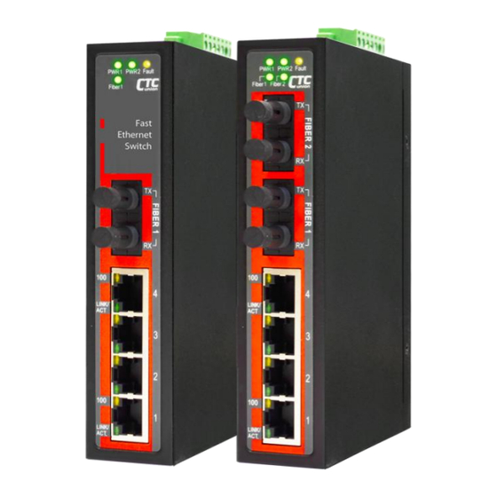
Panels Figure 3. Top Panel Figure 2. IFS-402F-(E) Figure 1. IFS-401F-(E) Front Panel Front Panel Description UTP RJ-45 ports Fiber ports Power, fault & fiber LED indicators DIP switch Power & Alarm connections Earth ground connector Earth ground sign... -
Page 9: Lan & Fiber Ports
LAN & Fiber Ports IFS-401F-(E) & IFS-402F-(E) models have 4 LAN ports (labeled 1~4) and one fixed fiber port (labeled FIBER) or two fixed fiber ports respectively on the front panel. The LAN ports that all utilize shielded RJ- 45 connectors support speed of 10/100M; while the fixed fiber ports support speed of 100M. -
Page 10: Recommended Power, Alarm, Ground Wiring Scheme
Recommended Power, Alarm, Ground Wiring Scheme DC Power Connection A removable terminal block on the top panel provides both power and alarm connections. Power can be provided through the dual inputs from separate sources (PWR1 & PWR2). One power supply is enough to power up the device. -
Page 11: Alarm Relay Connection
Alarm Relay Connection The alarm relay contact can be wired into an alarm circuit which senses an alarm condition when the contact is broken. The alarm relay is normally closed when there is no alarm condition. The alarm conditions are user programmable through management to include power, link faults or other fault conditions. -
Page 12: Led Indicators
LED Indicators Color Status Definition Power is connected and active at the PWR1 PWR1/PWR2 input terminal Green PWR2 connection. PWR1/PWR2 is not connected. One of the power inputs has fault condition (Alarm DIP switch must be enabled). Fault Amber Normal operation without power faults or Alarm DIP switch is disabled. -
Page 13: Installation
Installation The switch can be mounted on the wall or installed in DIN rail depending on your installation needs. When installing the wall-mounting bracket (optional accessory) and DIN rail bracket, be sure to correctly align the orientation pin. Figure 9. DIN Rail Figure 10. - Page 14 Version Date Description 2020/7/31 Use new document format Revise spec. 2021/3/23 Revise power spec. in Features.
Need help?
Do you have a question about the IFS-401F and is the answer not in the manual?
Questions and answers