
Related Manuals for CTC Union IQS-402XSM-4PH


Summary of Contents for CTC Union IQS-402XSM-4PH
- Page 1 Quick Installation Guide IQS-402XSM-4PH Industrial 4 x 10M/100M/1G/2.5G Base-T RJ-45 + 2 x 100M/1G/2.5G/10G Base-X SFP with 4 x PoE Managed Switch sales@ctcu.com...
- Page 2 8F, No. 60 Zhouzi St., Neihu, Taipei 114, Taiwan T +886-2-26591021 F +886-2-26590237 E sales@ctcu.com H www.ctcu.com 2021 CTC Union Technologies Co., LTD. All trademarks are the property of their respective owners. Technical information in this document is subject to change without notice.
-
Page 3: Table Of Contents
Table of Contents Introduction .................. 4 Package List ................. 4 Features ..................4 Access to Command Line Interface (CLI) ........5 /SSH C ..................5 ELNET ONNECTION Access to Web-Based Management Interface ......6 Specifications ................7 .................... 7 THERNET NTERFACE ...................... -
Page 4: Introduction
Introduction IQS-402XSM-4PH models are managed industrial grade Gigabit PoE (Power over Ethernet) switches with 4 x 10M/100M/1G/2.5G RJ-45 ports (with PoE function) and 2 x 100M/1G/2.5G/10G SFP+ slots. Housed in rugged DIN rail or wall mountable enclosures with fanless design,... -
Page 5: Access To Command Line Interface (Cli)
Access to Command Line Interface (CLI) IQS-402XSM-4PH models are managed Gigabit PoE switch devices. Initial configuration (assignment of IP address) may be accomplished via RJ45 Ethernet port running Telnet or SSH. Accessing the switch via Ethernet port allows the user to use Command Line Interface (CLI) to manage and configure the device. -
Page 6: Access To Web-Based Management Interface
Access to Web-Based Management Interface To enter the web-based management interface for the first time or after returning the device back to factory defaults, input the default IP 10.1.1.1 address “ ” in your web browser. Then, a standard login prompt will appear depending on the type of browser used. -
Page 7: Specifications
Specifications Ethernet Interface • Standards: IEEE802.3 (10Base-T), 802.3u (100Base-TX), 802.3ab (1000Base-T), 802.3bz (2.5GBase-T) • RJ-45 (shielded) Ports: 4 ports • Speed: 10M/100M/1000M/2.5G (Auto) Optical • Standards: 802.3z (1000Base-X) , 802.3cb (2.5GBase-X), 802.3ae (10Gbits Ethernet over Fiber) • SFP-Based Slots: 2 slots (Support DDMI) •... -
Page 8: Power
Power • Redundant dual 48VDC (44~57VDC) power inputs • 50~57VDC power input is recommended for IEEE802.3at PoE+ 30W applications • Support Power Input Reverse Polarity Protection • Support Dual Power Inputs • Support Removable Terminal Block • Consumption: Total Power Device Power PoE Power Input Voltage... -
Page 9: Panels
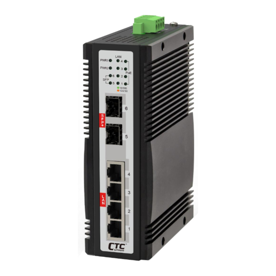
Panels Figure 2. Top Panel Figure 1. Front Panel Description 10M/100M/1G/2.5G RJ-45 ports (Support PoE function) 1G/2.5G/10G SFP+ slots Power, LAN, Fiber & PoE LED indicators Terminal block for power and alarm connection Reset-to-default push button Earth grounding connection... -
Page 10: Lan And Fiber Ports
LAN and Fiber Ports IQS-402XSM-4PH models have 4 LAN ports (labeled 1~4) and 2 fiber ports (SFP+ based, labeled Fiber 5~6) on the front panel. The LAN ports that utilize shielded RJ-45 connectors support 10M/100M/1G/2.5G; while the fiber SFP ports support 100M/1G/2.5G/10G. -
Page 11: Recommended Power, Alarm, Ground Wiring Scheme
Recommended Power, Alarm, Ground Wiring Scheme DC Power Connection A removable terminal block on the top panel provides both power and alarm connections. Power can be provided through the dual inputs from separate sources (PWR1 & PWR2). One power supply is enough to power up the device. -
Page 12: Alarm Relay Connection
Alarm Relay Connection The alarm relay contact can be wired into an alarm circuit which senses an alarm condition when the contact is broken. The alarm relay is normally closed when there is no alarm condition. The alarm conditions are user programmable through management to include power, link faults or other fault conditions. -
Page 13: Led Indicators
LED Indicators Color Status Meaning The switch is receiving power. Green The switch does not receive power or is in standby mode. When the LAN port is up and operating at 1G or 2.5G. Amber The LAN port is receiving and Blinking transmitting traffic. -
Page 14: Reset Push-Button
Reset Push-Button The "Reset" push-button provides the following two functions: Press and Function Description hold for~ Status Using a ball-point pen, press the "Reset" button and hold for 1~6 PWR LED seconds (less than 6 seconds) Reboot seconds blinks then release. The switch will clear all unsaved settings and restart. -
Page 15: Installation
Installation The switch can be mounted on the wall or installed in DIN rail depending on your installation needs. When installing the wall-mounting bracket (optional accessory) and DIN rail bracket, be sure to correctly align the orientation pin. Figure 8. DIN Rail Figure 9. - Page 16 Version Date Description 2021/2/25 Preliminary version 2021/5/3 2021/6/3 Revise power consumption...
Need help?
Do you have a question about the IQS-402XSM-4PH and is the answer not in the manual?
Questions and answers