
Related Manuals for CTC Union IGS-800C-8PH


Summary of Contents for CTC Union IGS-800C-8PH
- Page 1 Quick Installation Guide IGS-800C-8PH IGS-800C-8PHE 8 x GbE RJ-45 with 8 x PoE (240W, 48VDC) Compact-Sized Switch (Hardened) sales@ctcu.com...
- Page 2 8F, No. 60 Zhouzi St., Neihu, Taipei 114, Taiwan T +886-2-26591021 F +886-2-26590237 E sales@ctcu.com H www.ctcu.com 2020 CTC Union Technologies Co., LTD. All trademarks are the property of their respective owners. Technical information in this document is subject to change without notice.
- Page 3 CTC Union Technologies makes no warranty, representation, or guarantee regarding the suitability of its products for any particular purpose, nor does CTC Union assume any liability arising out of the application or use of any product and specifically disclaims any and all liability, including without limitation any consequential or incidental damages.
-
Page 4: Table Of Contents
Table of Contents Introduction .................. 5 Package List ................. 5 Features ..................5 Specifications ................6 .................... 6 THERNET NTERFACE ..................6 OWER OVER THERNET ......................6 OWER ...................... 7 ECHANICAL ....................7 NVIRONMENTAL ....................7 ERTIFICATIONS MTBF (MIL-HDBK-217) ..................7 Panels ................... -
Page 5: Introduction
Introduction IGS-800C-8PH(E) are unmanaged industrial grade Gigabit PoE (Power over Ethernet) switches that provide stable and reliable Ethernet transmission. Housed in rugged DIN rail or wall mountable enclosures, these switches are designed for harsh environments, such as industrial networking and intelligent transportation systems (ITS) and are also suitable for many military and utility market applications where environmental conditions exceed commercial product specifications. -
Page 6: Specifications
Specifications Ethernet Interface Standards: IEEE802.3, 802.3u, 802.3ab, 802.3x, 802.3af, 802.3at Connector Type: RJ-45 (shielded) Number of Connector: 8 ports Speed: 10/100/1000Base-T (Auto) Auto MDI/MDI-X Duplex: Full/Half (Auto-negotiation per IEEE802.3u) Support IEEE802.3x Flow Control ... -
Page 7: Mechanical
Dimensions: 100 mm (D) x 42 mm (W) x 115 mm (H) Installation Method: DIN Rail & Wall Mounting (Optional accessory) Weight: 950g Environmental Operating Temperature: -10°C~60°C (IGS-800C-8PH); -40°C~70°C (IGS- 800-8PHE) Humidity: 5%~95% (Non-condensing) Certifications ... -
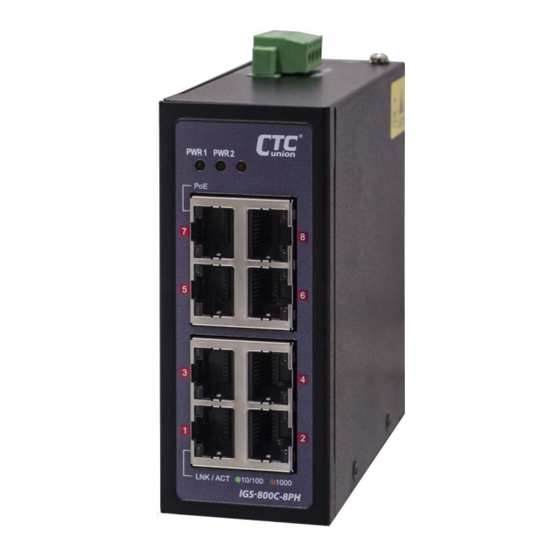
Page 8: Panels
Panels Index Description RJ-45 Ethernet Ports (1~8) Power LED Indicators PoE LED Indicators 10/100/1000 Link/Act LED Indicators Power Terminal Block Grounding Screw Figure 1. Front Panel Figure 2. Top Panel... -
Page 9: Connections
Ethernet transmission without any damage to the non-PoE device or to this device. NOTE: IGS-800C-8PH(E) is a PSE device that can connect to PDs (Powered Devices) or non-PoE devices. However, it is NOT recommended to connect IGS-800C-8PH(E) to another PSE device. By doing so, it may have potential risks to cause device damages. -
Page 10: Recommended Power & Ground Wiring Scheme
Recommended Power & Ground Wiring Scheme DC Power Connection A removable terminal block on the top panel provides power source connections. Power can be provided through the dual inputs from separate sources (PWR1 & PWR2). One power supply is enough to power up the device. -
Page 11: Earth Grounding Connection
Earth Grounding Connection An earth grounding connection hole is provided on the top panel with an earth ground sign next to it. Grounding the device can help to release leakage of electricity to the earth safely so as to reduce injuries from electromagnetic interference (EMI). -
Page 12: Installation
Installation The switch can be mounted on the wall or installed in DIN rail depending on your installation needs. When installing the wall-mounting bracket (optional accessory) and DIN rail bracket, be sure to correctly align the orientation pin. Figure 7. DIN Rail Figure 8. -
Page 13: Led Indicators
LED Indicators Color Status Definition Power is connected and active at the PWR1/PWR2 input terminal PWR1 Green connection. PWR2 PWR1/PWR2 is not connected. Lit when the LAN connected speed is 10/100M. Green Blinking when there is Ethernet Blinking traffic. LINK/ACT Lit when the LAN connected speed is 1000M. - Page 14 Version Date Description 2020/3/18 Preliminary version. -Revise weight info.
Need help?
Do you have a question about the IGS-800C-8PH and is the answer not in the manual?
Questions and answers