
Subscribe to Our Youtube Channel
Related Manuals for CTC Union ITP-800A


Summary of Contents for CTC Union ITP-800A
- Page 1 Quick Installation Guide ITP-800A ITP-800A-E EN50155 & EN45545-2 Switch sales@ctcu.com...
- Page 2 8F, No. 60 Zhouzi St., Neihu, Taipei 114, Taiwan T +886-2-26591021 F +886-2-26590237 E sales@ctcu.com H www.ctcu.com 2020 CTC Union Technologies Co., LTD. All trademarks are the property of their respective owners. Technical information in this document is subject to change without notice.
- Page 3 CTC Union Technologies makes no warranty, representation, or guarantee regarding the suitability of its products for any particular purpose, nor does CTC Union assume any liability arising out of the application or use of any product and specifically disclaims any and all liability, including without limitation any consequential or incidental damages.
-
Page 4: Table Of Contents
Table of Contents Introduction .................. 5 Package List ................. 5 Features ..................5 Specifications ................6 ................... 6 ETWORK NTERFACE ....................6 OWER UPPLY ...................... 6 ECHANICAL ....................6 NVIRONMENTAL ....................7 ERTIFICATIONS MTBF (MIL-HDBK-217) ..................7 Panels ................... 8 PIN Assignment ................ -
Page 5: Introduction
Introduction The ITP-800A(-E) is an unmanaged Fast Ethernet switch that provides eight 10/100Base-TX Fast Ethernet ports for industrial applications in harsh environments. The switches use M12 connectors as Ethernet ports so as to ensure tight, robust connections and guarantee reliable operation against environmental disturbances such as vibration and shock. -
Page 6: Specifications
Fanless Design Dimensions: 45 mm (D) x 71.5 mm (W) x 219 mm (H) Installation Method: Wall-mounting installation Weight: 420g Environmental Operating Temperature: -10°C~60°C (ITP-800A); -40°C~75°C (ITP- 800A-E) Storage Temperature: -40°C~85°C Humidity: 5%~95% (Non-condensing) -
Page 7: Certifications
Certifications EMC: CE (EN55024, EN55032) EMI (Electromagnetic Interference): FCC Part 15 Subpart B Class A, CE Railway Traffic: EN50155, EN50121-4 Fire Protection of Railway Vehicle: EN45545-2 Immunity for Heavy Industrial Environment: EN61000-6-2 Emission for Heavy Industrial Environment: EN61000-6-4 ... -
Page 8: Panels
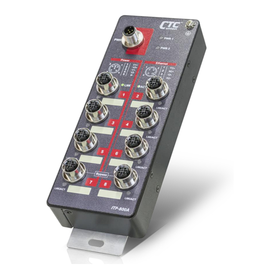
Panels Index Description Wall mounting holes Grounding screw M12 Power input port Power LED M12 Ethernet ports Ethernet port LED Ethernet port label Power port pin assignment table Ethernet port pin assignment table Figure 1. Front Panel... -
Page 9: Pin Assignment
PIN Assignment M12 Ethernet Cable Male M12 Connector Model: CAB-M12DM4-RJ45 Figure 2. M12 D-code Male to RJ-45 Socket Cable M12 Pins RJ-45 Pins Color Green / White Green Orange / White Orange M12 Power Input Cable Model: CAB-M12AF5-OPEN Female M12 Connector Figure 3. -
Page 10: M12 Cable Connector Installation
M12 Cable Connector Installation Before assembling M12 open cable, make sure you have the following M12 cable connector components (Model: M12D-M4 M12 D- Code Male) and open cable at hand. Male Contact Screw Nut Housing O-Ring Connector Assembly Steps: Step 1. Insert the screw nut, O-ring, and housing into the cable in the order shown in Figure 2 and keep them loose in this step. - Page 11 Step 3. Tighten the connector in clockwise direction, making sure that the wires inside the connector are not twisted as the screwed housing is assembled. Figure 6. Tighten the Connector...
-
Page 12: Bypass Relay Function
Bypass Relay Function ITP-800A(-E) provides two Ethernet interfaces (port 7 & 8) with auto bypass relay function in the event of sudden power loss particularly in daisy chain or linear topology. When power failure occurs in one of the switches, bypass relay function can activate bypassing mechanism by interconnecting internal circuits automatically to ensure that links between switches operate uninterruptedly and continuously. -
Page 13: Earth Ground Connection
Earth Ground Connection An earth grounding connection hole is provided in the upper right- hand corner of the front panel with an earth ground sign next to it. Grounding the device can help to release leakage of electricity to the earth safely so as to reduce injuries from electromagnetic interference (EMI). -
Page 14: Led Indicators
LED Indicators Color Status Description Lit if power 1 is connected and active. PWR1 Green Power is not connected. Lit if power 2 is connected and active. PWR2 Green Power is not connected. Lit when the LAN connected speed is 10M or 100M. -
Page 15: Application
Application Figure 10. On-board Train Application Diagram NOTES:... - Page 16 Version Date Description 2020/3/31 Use new document format.
Need help?
Do you have a question about the ITP-800A and is the answer not in the manual?
Questions and answers