Table of Contents
Advertisement
Quick Links
Advertisement
Table of Contents

Related Manuals for CTC Union ITP-1204GTM-12PHE


Summary of Contents for CTC Union ITP-1204GTM-12PHE
- Page 1 Quick Installation Guide ITP-1204GTM-12PHE ITP-1204GTM-12PHE-BP 12 x 10/100Base-TX M12 + 4 x GbE M12 with 12 x PoE (120W, 24/48/72/110VDC) 12 x 10/100Base-TX M12 + 4 x GbE M12 with 12 x PoE & Built- in Bypass Function (120W, 24/48/72/110VDC)
- Page 2 8F, No. 60 Zhouzi St., Neihu, Taipei 114, Taiwan T +886-2-26591021 F +886-2-26590237 E sales@ctcu.com H www.ctcu.com 2020 CTC Union Technologies Co., LTD. All trademarks are the property of their respective owners. Technical information in this document is subject to change without notice.
-
Page 3: Table Of Contents
Table of Contents Introduction .................. 4 Package List ................. 4 Features ..................4 Access to Command Line Interface (CLI) ........5 ..................5 ONSOLE ONNECTION /SSH C ..................6 ELNET ONNECTION Access to Web-Based Management Interface ......7 Specifications ................8 ...................... -
Page 4: Introduction
Introduction The ITP-1204GTM-12PH & ITP-1204GTM-12PH-BP are managed Industrial Grade Ethernet PoE+ switches that provide 12 x 10/100Base- TX Fast Ethernet UTP plus 4 x 10/100/1000Base-T with 12 PoE ports. ITP- 1204GTM-12PH & ITP-1204GTM-12PH-BP switches equipped with PoE (Power over Ethernet) function utilize M12 connectors to ensure tight and robust connections as well as to guarantee reliable operation against environmental disturbances such as vibration and shock. -
Page 5: Access To Command Line Interface (Cli)
Access to Command Line Interface (CLI) are managed ITP-1204GTM-12PH & ITP-1204GTM-12PH-BP Ethernet PoE+ switches for industrial uses. Initial configurations can be accomplished via the M12 CONSOLE port and a PC or laptop running terminal emulation software or via the M12 Ethernet port running Telnet or SSH. -
Page 6: Telnet/Ssh Connection
Telnet/SSH Connection To use Command Line Interface (CLI), you can also choose to access the device through a Telnet/SSH connection via TCP/IP network over Ethernet ports. For initial operation, use the default TCP/IP settings (10.1.1.1) to login to the device. Default TCP/IP settings: IP Address: 10.1.1.1 Subnet Mask: 255.255.255.0... -
Page 7: Access To Web-Based Management Interface
Access to Web-Based Management Interface To enter the web-based management interface for the first time or after returning the device back to factory defaults, input the default IP 10.1.1.1 address “ ” in your web browser. Then, a standard login prompt will appear depending on the type of browser used. -
Page 8: Specifications
Specifications Interface 12 x 10/100Base-TX UTP(M12, 4-Pin, D-Code Female) + 4 x 10/100/1000Base-T UTP (M12, 8-Pin, X-Code Female) Port 15 & 16 support bypass function (ITP-1204GTM-12PH-BP Series only) Support Auto MDI/MDI-X Support Full/Half Duplex IEEE 802.3x Flow Control for full duplex; Back pressure for half duplex mode ... -
Page 9: Mechanical
Mechanical Housing: IP54 grade rugged metal housing protection Fanless design Dimensions: 113 mm (D) x 260 mm (W) x 132 mm (H) Installation Method: Wall-mounting Weight: 2.8kg Environmental Operating Temperature: -40°C~75°C Storage Temperature: -40°C~85°C ... -
Page 10: Panels
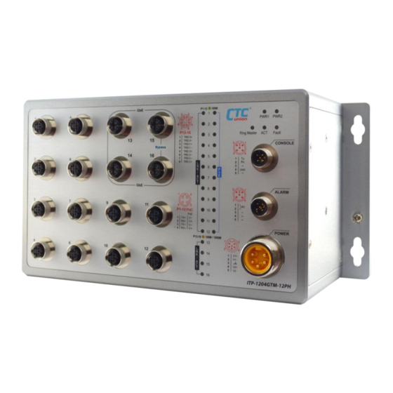
Panels ITP-1204GTM-12PH Figure 1. ITP-1204GTM-12PH Front Panel Index No. Description M12 D-Code Fast Ethernet Port 1~12 M12 X-Code Gigabit Ethernet Port 13~16 M12 Console Port M12 Alarm Port M23 Power Input Port Power 1 & 2, Fault, ACT, Ring LED Indicators Link/ACT &... -
Page 11: Itp-1204Gtm-12Ph-Bp
ITP-1204GTM-12PH-BP 10 8 Figure 2. ITP-1204GTM-12PH-BP Front Panel Index No. Description M12 D-Code Fast Ethernet Port 1~12 M12 X-Code Gigabit Ethernet Port 13~16 (Port 15 & 16 are built-in bypass ports) M12 Console Port M12 Alarm Port M23 Power Input port Power 1 &... -
Page 12: Pin Assignment
PIN Assignment M12 Fast Ethernet Port (D-Code) Model: CAB-M12DM4-RJ45 Port 1~12 Fast Ethernet PoE Pinout M12 Pin Pinout RJ-45 Pin No. Table 1. Fast Ethernet Cable Pin Assignment M12 Gigabit Ethernet Port (X-Code) Model: CAB-M12XM8-RJ45 Port 13~16 Gigabit Ethernet M12 Pin No. Pinout RJ-45 Pin No. -
Page 13: M12 Console Port
M12 Console Port DB-9 (Female) Pinout M12 Pinout Table 3. Console Cable Pin Assignment M12 Alarm Port Color of M12 Pin No. Description Open Cable Black Normal (Relay Closed) Blue Fault (Relay Open) Orange Yellow Table 4. Alarm Cable Pin Assignment M23 Power Input Port M23 Pin No. -
Page 14: M12 Cable Connector Installation
M12 Cable Connector Installation Before assembling M12 open cable, make sure you have the following M12 cable connector components (Model: M12D-M4 M12 D- Code Male) and open cable at hand. Male Contact Housing Screw Nut O-Ring Connector Assembly Steps: Step 1. Insert the screw nut, O-ring, and housing into the cable in the order shown in the figure below and keep them loose in this step. - Page 15 Step 3. Tighten the connector in clockwise direction, making sure that the wires inside the connector are not twisted as the screwed housing is assembled. Figure 5. Tighten the Connector...
-
Page 16: Earth Ground Connection
Earth Grounding Connection An earth grounding connection hole is provided on the lower right-hand corner of the wall-mounting plate. Grounding the device can help to release leakage of electricity to the earth safely so as to reduce injuries from electromagnetic interference (EMI). Prior to connecting to the power, it is important to connect the ground wire to the earth. -
Page 17: Led Indicators
LED Indicators Color Status Description Lit if power 1 is connected and PWR1 Green active. Lit if power 2 is connected and PWR2 Green active. Lit when one or more of the Fault Amber programmable alarm conditions is active. During normal use, this LED will be lit, indicating a healthy condition of the running CPU. -
Page 18: Wall-Mounting Installation
Wall-Mounting Installation The Ethernet Switch can be mounted on the wall using the attached wall-mounting plate with four wall-mounting holes. The installation is simple and easy. Before installing the Ethernet Switch on the wall, you have to prepare four suitable wall screws for wall mounting. Installation steps are as follows: Step 1. -
Page 19: Application
Application Figure 9. Onboard Train Application for ITP Series... - Page 20 Version Date Description 2020/2/14 Preliminary version.
Need help?
Do you have a question about the ITP-1204GTM-12PHE and is the answer not in the manual?
Questions and answers