
Related Manuals for CTC Union IGS-1604XSM-16PH


Summary of Contents for CTC Union IGS-1604XSM-16PH
- Page 1 Quick Installation Guide IGS-1604XSM-16PH Industrial 16 x 10M/100M/1000Base-T RJ-45 + 4 x 1G/2.5G/5G/10G Base-X SFP with 16 x PoE Managed Switch sales@ctcu.com...
- Page 2 8F, No. 60 Zhouzi St., Neihu, Taipei 114, Taiwan T +886-2-26591021 F +886-2-26590237 E sales@ctcu.com H www.ctcu.com 2023 CTC Union Technologies Co., LTD. All trademarks are the property of their respective owners. Technical information in this document is subject to change without notice.
-
Page 3: Table Of Contents
Table of Contents Introduction .................. 4 Package List ................. 4 Features ..................4 Access to Command Line Interface (CLI) ........5 ..................5 ONSOLE ONNECTION /SSH C ..................6 ELNET ONNECTION Access to Web-Based Management Interface ......7 Specifications ................8 .................... -
Page 4: Introduction
Introduction IGS-1604XSM-16PH models are industrial grade managed PoE (Power over Ethernet) switches with 16 Gigabit Ethernet RJ-45 connectors and four 10 Gigabit SFP+ slots that offer long-distance and wide bandwidth transmission. Each RJ-45 port not only provides stable and reliable Ethernet transmission but also provides IEEE802.af &... -
Page 5: Access To Command Line Interface (Cli)
Access to Command Line Interface (CLI) IGS-1604XSM-16PH models are managed PoE switch devices. Initial configuration (assignment of IP address) may be accomplished via the RS-232 console and a PC or laptop running terminal emulation software or via RJ45 Ethernet port running Telnet or SSH. -
Page 6: Telnet/Ssh Connection
Telnet/SSH Connection To use Command Line Interface (CLI), you can choose to access the device through a Telnet or SSH connection via TCP/IP network over Ethernet ports. For initial operation, use the default TCP/IP settings (10.1.1.1) to login to the device. Default TCP/IP settings: IP Address: 10.1.1.1 Subnet Mask: 255.255.255.0... -
Page 7: Access To Web-Based Management Interface
Access to Web-Based Management Interface To enter the web-based management interface for the first time or after returning the device back to factory defaults, input the default IP 10.1.1.1 address “ ” in your web browser. Then, a standard login prompt will appear depending on the type of browser used. -
Page 8: Specifications
Specifications Ethernet Interface Standards: IEEE802.3 (10Base-T), 802.3u (100Base-TX), 802.3ab (1000Base-T) RJ45 (shielded) Ports: 16 ports Speed: 10M/100M/1000M (Auto) Optical Interface Standards: 802.3z (1000Base-X), 802.3ae (10G Ethernet over Fiber) SFP-Based Slots: 4 slots (Support DDMI) Speed: 1G/2.5G/5G/10Gbps Power over Ethernet ... -
Page 9: Mechanical
Mechanical Water & Dust Proof: IP30 Protection Dimensions: 155.6mm (D) x 77 mm (W) x 160 mm (H) Mounting: DIN-Rail, Wall Mount (Optional) Weight: 2065 g Environmental Operating Temperature: -40°C~60°C Storage Temperature: -40°C~85°C Humidity: 5%~95% (Non-condensing) Certifications ... -
Page 10: Panels
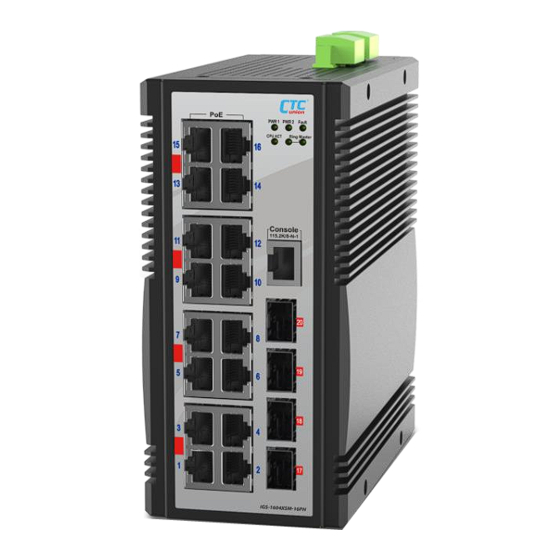
Panels Figure 2. Top Panel Figure 1. Front Panel Description 10M/100M/1000M RJ-45 LAN ports 1G/2.5G/5G/10G SFP+ slots Console port (RS-232 to RJ45) Power, Fault, CPU ACT & Ring Master LED indicators Link activity & speed LED indicator for RJ-45 LAN port LED indicator for PoE function Link activity &... -
Page 11: Lan And Fiber Ports
LAN and Fiber Ports IGS-1604XSM-16PH models have 16 LAN ports (labeled 1~16) and 4 fiber ports (SFP+ based, labeled 17~20) on the front panel. Each LAN port that utilize shielded RJ-45 connectors supports speed of 10M/100M/1000M; while each fiber SFP slot supports speed of 100M/1G/2.5G/10G. -
Page 12: Recommended Power, Alarm (Do), Di & Ground Wiring Scheme
Recommended Power, Alarm (DO), DI & Ground Wiring Scheme DC Power Connection Two removable terminal blocks on the top panel provide connections to two power supplies, DO (alarm relay) device and DI device. Power can be provided through the dual inputs from separate sources (PWR1 &... -
Page 13: Alarm (Do) Connection
Alarm (DO) Connection The digital output (DO) can be wired into an alarm circuit which senses an alarm condition when the contact is broken. The alarm relay is normally closed when there is no alarm condition. The alarm conditions are user programmable through management to include power, link faults or other fault conditions. -
Page 14: Earth Ground Connection
Earth Ground Connection An earth ground connector is provided on the top panel with an earth ground sign next to it. Grounding the device can help to release leakage of electricity to the earth safely so as to reduce injuries from electromagnetic interference (EMI). -
Page 15: Led Indicators
LED Indicators Color Status Definition Power is connected and active at the PWR1/PWR2 input terminal PWR1/ Green connection. PWR2 PWR1/PWR2 is not connected. When one or more of the programmable alarm conditions is active. Fault Amber Normal operation without faults. Alarm conditions are all disabled. -
Page 16: Installation
Installation The switch can be mounted on the wall or installed in DIN rail depending on your installation needs. When installing the wall-mounting bracket (optional accessory) and DIN rail bracket, be sure to correctly align the orientation pin. Figure 9. DIN Rail Figure 10. - Page 17 Version Date Description 0.9a 2022/11/8 Preliminary version 0.9b 2023/5/16 Remove pending from EN62368-1 certificate...
Need help?
Do you have a question about the IGS-1604XSM-16PH and is the answer not in the manual?
Questions and answers