
Related Manuals for CTC Union IGS-812SM Series


Summary of Contents for CTC Union IGS-812SM Series
- Page 1 IGS-812SM Series IGS-1604SM Series IFS-1604GSM Series Industrial Gigabit & Fast Ethernet 20-Port Managed Switches...
- Page 2 CTC Union Technologies makes no warranty, representation, or guarantee regarding the suitability of its products for any particular purpose, nor does CTC Union assume any liability arising out of the application or use of any product and specifically disclaims any and all liability, including without limitation any consequential or incidental damages.
- Page 3 This document is the current official release manual. Contents are subject to change without prior notice. Please check CTC Union's website for any updated manual or contact us by E-mail at sales@ctcu.com. Please address any comments for improving this manual or to point out omissions or errors to marketing@ctcu.com. Thank you.
-
Page 4: Table Of Contents
TABLE OF CONTENTS CHAPTER 1. INTRODUCTION ..................... 17 1.1 W ............................. 17 ELCOME 1.2 P ........................17 RODUCT ESCRIPTION 1.2.1 IGS-812SM ............................... 17 1.2.2 IGS-1604SM ..............................18 1.2.3 IFS-1604GSM..............................18 1.3 P ......................... 19 RODUCT EATURES 1.4 P ......................... 20 RODUCT PECIFICATIONS CHAPTER 2. - Page 5 TABLE OF CONTENTS 3.8.3 # clear dot1x statistics ............................. 36 3.8.4 # clear erps............................... 36 3.8.5 # clear ip arp ..............................36 3.8.6 # clear ip dhcp detailed statistics ........................36 3.8.7 # clear ip dhcp relay statistics .......................... 36 3.8.8 # clear ip dhcp snooping statistics ........................
- Page 6 TABLE OF CONTENTS 3.9.3.10 (config-if)# access-list shutdown ..........................51 3.9.3.11 (config-if)# access-list { redirect | port-copy } ......................51 3.9.4 (config)# aggregation ............................51 3.9.4.1 (config)# aggregation mode ............................51 3.9.4.2 (config-if)# aggregation group ............................52 3.9.5 (config)# banner............................... 52 3.9.5.1 (config)# banner [ motd ] <banner> ..........................52 3.9.5.2 (config)# banner exec <banner>...
- Page 7 TABLE OF CONTENTS 3.9.15.1 (config)# gvrp................................69 3.9.15.2 (config)# gvrp max-vlans ............................69 3.9.15.3 (config)# gvrp time ..............................70 3.9.15.4 (config-if)# gvrp ................................70 3.9.16 (config)# hostname ............................70 3.9.17 (config)# interface ............................71 3.9.17.1(config)# interface ( <port_type> [ <plist> ] ) ......................71 3.9.17.2 (config)# interface vlan ...............................72 3.9.18 (config)# ip ..............................
- Page 8 TABLE OF CONTENTS 3.9.18.50 (config-if-vlan)# ipv6 mld snooping last-member-query-interval ................87 3.9.18.51 (config-if-vlan)# ipv6 mld snooping priority <cos_priority> ..................88 3.9.18.52 (config-if-vlan)# ipv6 mld snooping querier election ....................88 3.9.18.53 (config-if-vlan)# ipv6 mld snooping query-interval <ipmc_qi> .................88 3.9.18.54 (config-if-vlan)# ipv6 mld snooping query-max-response-time <ipmc_qri>.............88 3.9.18.55 (config-if-vlan)# ipv6 mld snooping robustness-variable <ipmc_rv>...
- Page 9 TABLE OF CONTENTS 3.9.23.10 (config)# lldp med location-tlv latitude ........................108 3.9.23.11 (config)# lldp med location-tlv longitude .......................109 3.9.23.12 (config)# lldp med media-vlan-policy ........................109 3.9.23.13 (config-if)# lldp cdp-aware .............................110 3.9.23.14 (config-if)# lldp med media-vlan policy-list ......................110 3.9.23.15 (config-if)# lldp med transmit-tlv..........................110 3.9.23.16 (config-if)# lldp receive ............................111 3.9.23.17 (config-if)# lldp tlv-select ............................111 3.9.23.18 (config-if)# lldp transmit ............................111...
- Page 10 TABLE OF CONTENTS 3.9.31.4 (config)# mvr name <mvr_name> frame tagged ......................129 3.9.31.5 (config)# mvr name <mvr_name> igmp-address ......................129 3.9.31.6 (config)# mvr name <mvr_name> last-member-query-interval ................130 3.9.31.7 (config)# mvr name <mvr_name> mode ........................130 3.9.31.8 (config)# mvr vlan <v_vlan_list> ..........................131 3.9.31.9 (config)# mvr vlan <v_vlan_list> channel .........................131 3.9.31.10 (config)# mvr vlan <v_vlan_list>...
- Page 11 TABLE OF CONTENTS 3.9.37.14 (config-if)# qos dscp-translate ..........................155 3.9.37.15 (config-if)# qos map cos-tag cos ..........................155 3.9.37.16 (config-if)# qos map tag-cos pcp ..........................155 3.9.37.17 (config-if)# qos pcp ..............................156 3.9.37.18 (config-if)# qos policer ............................156 3.9.37.19 (config-if)# qos queue-policer queue ........................157 3.9.37.20 (config-if)# qos queue-shaper queue ........................157 3.9.37.21 (config-if)# qos shaper ............................157 3.9.37.22 (config-if)# qos tag-remark .............................158 3.9.37.23 (config-if)# qos trust dscp ............................158...
- Page 12 TABLE OF CONTENTS 3.9.43.17 (config-snmps-host)# host <v_ipv6_ucast> ......................176 3.9.43.18 (config-snmps-host)# host <v_ipv4_ucast> ......................176 3.9.43.19 (config-snmps-host)# version ..........................177 3.9.43.20 (config-snmps-host)# informs retries ........................177 3.9.43.21 (config-snmps-host)# shutdown ..........................178 3.9.43.22 (config-snmps-host)# traps.............................178 3.9.44 (config)# spanning-tree ..........................179 3.9.44.1 (config)# spanning-tree aggregation ........................179 3.9.44.2 (config-stp-aggr)# spanning-tree ..........................179 3.9.44.3 (config-stp-aggr)# spanning-tree auto-edge ......................179 3.9.44.4 (config-stp-aggr)# spanning-tree bpdu-guard ......................179 3.9.44.5 (config-stp-aggr)# spanning-tree edge ........................180...
- Page 13 TABLE OF CONTENTS 3.9.47.2 (config)# tacacs-server deadtime ..........................196 3.9.47.3 (config)# tacacs-server key ............................196 3.9.47.4 (config)# tacacs-server host .............................197 3.9.48 (config)# upnp .............................. 197 3.9.48.1 (config)# upnp ................................197 3.9.48.2 (config)# upnp advertising-duration .........................197 3.9.48.3 (config)# upnp ttl ..............................198 3.9.49 (config)# username ............................198 3.9.49.1 (config)# username<username>privilege<priv>password encrypted ..............198 3.9.49.2 (config)# username<username>privilege<priv>password none ................199 3.9.49.3 (config)# username<username>privilege<priv>password unencrypted ..............199...
- Page 14 TABLE OF CONTENTS 4.5.2.2 Access Management Statistics ...........................229 4.5.3 SNMP ................................229 4.5.3.1 SNMP System Configuration............................229 4.5.3.2 Alarm Configuration ..............................230 4.5.3.3 SNMPv3 Community Configuration ..........................234 4.5.3.4 SNMPv3 User Configuration ............................234 4.5.3.5 SNMPv3 Group Configuration ............................235 4.5.3.6 SNMPv3 View Configuration ............................236 4.5.3.7 SNMPv3 Access Configuration ............................236 4.5.4 RMON ................................
- Page 15 TABLE OF CONTENTS 4.6.2.4 Port Statistics ................................275 4.7 R ..........................276 EDUNDANCY 4.7.1 u-Ring ................................276 4.7.1.1 Configuration ................................276 4.7.1.2 Status ..................................278 4.7.2 Loop Protection ............................. 279 4.7.2.1 Configuration ................................279 4.7.2.2 Status ..................................281 4.7.3 Spanning Tree ..............................281 4.7.3.1 Bridge Settings ................................282 4.7.3.2 MSTI Mapping ................................283 4.7.3.3 MSTI Priorities ................................284 4.7.3.4 CIST Ports..................................285...
- Page 16 TABLE OF CONTENTS 4.15.2 Ports Configuration ............................330 4.15.3 Membership Status ............................332 4.15.4 Port Status ..............................332 4.16 P VLAN .......................... 333 RIVATE 4.16.1 PVLAN Membership ............................. 333 4.16.2 Port Isolation..............................333 4.17 VCL ............................334 4.17.1 MAC-based..............................334 4.17.1.1 Membership Configuration ............................334 4.17.1.2 Membership Status ..............................335 4.17.2 Protocol-based VLAN ...........................
-
Page 17: Chapter 1. Introduction
CHAPTER 1. INTRODUCTION 1.1 Welcome Welcome and thank you for purchasing this "Industrial Strength" product from CTC Union. We hope this product is everything you wanted and more. Our Product Managers and R&D team have placed a "quality first" motto in our development of this series of Ethernet switches with the desire of providing a highly stable and reliable product that will give years of trouble free operation. -
Page 18: Igs-1604Sm
CHAPTER 1 INTRODUCTION 1.2.2 IGS-1604SM The IGS-1604SM is an Industrial Gigabit Ethernet Switch (IGS) for commercial temperature range of -10°C to +60°C. There are 16 LAN ports with RJ-45 connectors that support 10M/100M/1000M Ethernet. There are 4 fiber ports that support 100M/1000M dual rate speed and utilize SFP cages that support any industry standard Fast or Gigabit SFP module. -
Page 19: Product Features
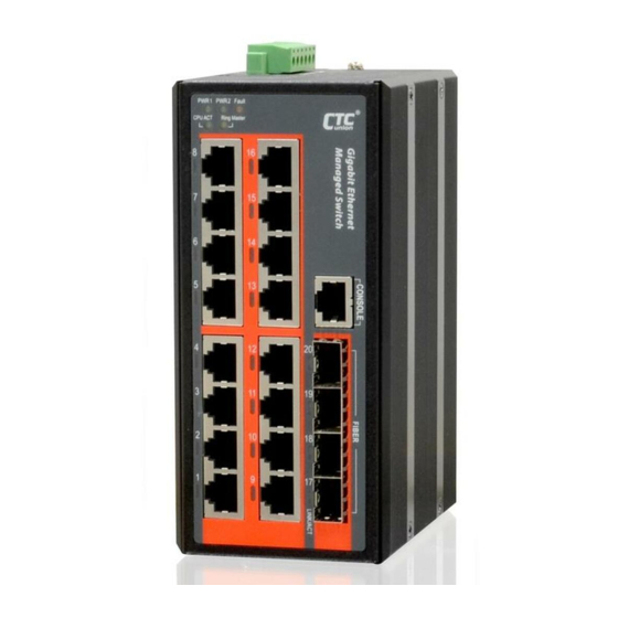
16 x 10/100Base-TX RJ-45 with 4 x 100/1000Base-X SFP Fiber (IFS-1604GSM Series) 16 x 10/100/1000Base-T RJ-45 with 4 x 100/1000Base-X SFP Fiber (IGS-1604SM Series) 8 x 10/100/1000Base-T RJ-45 with 12 x 100/1000Base-X SFP Fiber (IGS-812SM Series) 12/24/48VDC (9.6VDC~60VDC) Redundant dual DC inputs ... -
Page 20: Product Specifications
CHAPTER 1 INTRODUCTION 1.4 Product Specifications IEEE 802.3 10Base-T 10Mbit/s Ethernet IEEE 802.3u 100Base-TX, 100Base-FX, Fast Ethernet IEEE 802.3ab 1000Base-T Gbit/s Ethernet over twisted pair IEEE 802.3z 1000Base-X Gbit/s Ethernet over Fiber-Optic IEEE 802.1d STP (Spanning Tree Protocol) IEEE 802.1w RSTP (Rapid Spanning Tree Protocol ) IEEE 802.1s MSTP (Multiple Spanning Tree Protocol ) -
Page 21: Chapter 2. Panels & Installation
CHAPTER 2 PANELS & INSTALLATION CHAPTER 2. PANELS & INSTALLATION 2.1 Views of Panels Each physical feature on the panels is indexed numerically and explained briefly in the reference box on the right side. Detailed descriptions for each feature are also provided in the following sub-sections. Index Reference RJ-45 LAN ports SFP-based fiber... -
Page 22: Lan Connections
CHAPTER 2 PANELS & INSTALLATION 2.2 LAN Connections Front of unit Depending on the model that you purchased, there are 16 or 8 shielded RJ-45 that provide LAN connection to the Switch. On the IFS Series, these provide Ethernet for 10/100M connection. On the IGS Series, these ports are 10/100/1000M. -
Page 23: Console Port Connection
CHAPTER 2 PANELS & INSTALLATION 2.4 Console Port Connection IFS/IGS Series have an asynchronous terminal console port for local management via a serial terminal. The terminal provides management via a CLI (Command Line Interface) which will be familiar to many networking engineers. -
Page 24: Power & Alarm
CHAPTER 2 PANELS & INSTALLATION 2.5 Power & Alarm IFS/IGS Series uses a removable terminal block for connection of DC power and Alarm. This device supports dual input from two different DC power sources so that in the event of a single source failure, the IFS/IGS device will continue to function normally. -
Page 25: Led Indicators
CHAPTER 2 PANELS & INSTALLATION 2.7 LED Indicators Color Status Meaning Power is connected and active at the PWR1/PWR2 input PWR 1 Green terminal connection. PWR 2 PWR1/PWR2 input terminal is not connected. When one or more of the programmable alarm conditions is Fault Amber active. -
Page 26: Un-Mounting
CHAPTER 2 PANELS & INSTALLATION 2.8.2 Un-mounting IFS/IGS Series with DIN Rail bracket has a steel spring in the upper rail of the bracket. This spring is compressed for mounting and un-mounting by applying downward force. Mounting Un-mounting... -
Page 27: Chapter 3. Introduction To Cli
CHAPTER 3 CLI CONFIGURATION CHAPTER 3. INTRODUCTION TO CLI 3.1 General Introduction The IFS/IGS Series of industrial Ethernet switches provide a number of configuration/management methods. The first and very basic is serial console access. This method is also called out-of-band management and is only available when a terminal or administrator PC can be physically connected to the local IFS/IGS Series switch at the CONSOLE port using RJ45 to RS-232 console cable. -
Page 28: Cli Modes
CHAPTER 3 CLI CONFIGURATION 3.3 CLI Modes The Command Line Interface (CLI) of IFS/IGS series is mainly divided into four basic modes; these are User mode, EXEC mode, Config mode and Config Interface mode. After entering the username and password, you start from the Exec mode (prompted with “#”). -
Page 29: Basic Configurations
CHAPTER 3 CLI CONFIGURATION separate them. 2. The uter curly bracket means that this is a must parameter. At leaset one value should be specified. | (Vertical Use a vertical bar to separate { { <address> <netmask> } | Enter IP address or use bar) options. -
Page 30: Save Configurations
CHAPTER 3 CLI CONFIGURATION 3.6.3 Save Configurations # copy running-config startup-config Building configuration... % Saving 1469 bytes to flash:startup-config 3.6.4 Restart the Device # reload cold % Cold reload in progress, please stand by. Copyright (C) 2000, 2001, 2002, 2003, 2004, 2005, 2006, 2007, 2008, 2009 Free Software Foundation, Inc. -
Page 31: Show Sfp Information
Software Version : "1.100" Build Date : 2015-04-17T09:22:35+08:00 3.6.7 Show SFP Information # show sfp ---------- Vendor Name : CTC UNION Vendor Part Number : SFS-7020-WA-DDI Fiber Type : Single Wave Length : 1310 nm Wave Length 2 : 1550 nm... -
Page 32: Show History Commands
CHAPTER 3 CLI CONFIGURATION interface FastEthernet 1/2 no spanning-tree interface FastEthernet 1/3 no spanning-tree interface FastEthernet 1/4 no spanning-tree -- more --, next page: Space, continue: g, quit: ^C 3.6.9 Show History Commands # show history config t exit config t ip arp ex exit >... -
Page 33: Logout
CHAPTER 3 CLI CONFIGURATION 3.6.11 Logout To close an active terminal session, issue the “logout” command in User or EXEC mode. (config)# exit # logout Press ENTER to get started # disable > logout Press ENTER to get started 3.7 Commands in User Mode When you successfully login in Command Line Interface, you are in Exec Mode (prompted with “#”). -
Page 34: Enable
CHAPTER 3 CLI CONFIGURATION Explanation: Clear statistics of the specified interfaces. 3.7.4 > enable Syntax: > enable [ <new_priv> ] [ <new_priv: 0-15> ]: Choose a privilege level. Explanation: Enter the Exec mode. 3.7.5 > exit Syntax: > exit Explanation: Return to the previous mode. Issuing this command in User mode will logout the Command Line Interface. -
Page 35: Ping Ipv6
CHAPTER 3 CLI CONFIGURATION 3.7.9 > ping ipv6 Syntax: > ping ipv6 <v_ipv6_addr> [ repeat <count> ] [ size <size> ] [ interval <seconds> ] <v_ipv6_addr>: Specify IPv6 address that you want to ping. [ repeat <count> ]: The number of packets that are sent to the destination IP or host. [ size <size>... -
Page 36: Clear Dot1X Statistics
CHAPTER 3 CLI CONFIGURATION 3.8.3 # clear dot1x statistics Syntax: # clear dot1x statistics [ interface ( <port_type> [ <v_port_type_list> ] ) ] Parameter: [ interface ( <* | FastEthernet | GigabitEthernet> [ <v_port_type_list> ] ) ]: Specify the interface that you want to clear. -
Page 37: Clear Ip Dhcp Snooping Statistics
CHAPTER 3 CLI CONFIGURATION 3.8.8 # clear ip dhcp snooping statistics Syntax: # clear ip dhcp snooping statistics [ interface ( <port_type> [ <in_port_list> ] ) ] Explanation: Clear IP DHCP Snooping statistics. 3.8.9 # clear ip igmp snooping Syntax: # clear ip igmp snooping [ vlan <v_vlan_list> ] statistics Explanation: Clear IP IGMP Snooping statistics. -
Page 38: Clear Lldp Statistics
CHAPTER 3 CLI CONFIGURATION 3.8.15 # clear lldp statistics Syntax: # clear lldp statistics Explanation: Clear LLDP statistics. 3.8.16 # clear logging Syntax: # clear logging [ info ] [ warning ] [ error ] [ switch <switch_list> ] Explanation: Clear specific syslog events. 3.8.17 # clear mac address-table Syntax: # clear mac address-table Explanation: Clear MAC address table. -
Page 39: Config Terminal
CHAPTER 3 CLI CONFIGURATION 3.8.22 # config terminal Syntax: # config terminal Explanation: Enter the Global Config mode. Example: # config t (config)# 3.8.23 # copy Syntax: # copy { startup-config | running-config | <source_path> } { startup-config | running-config | <destination_path>... -
Page 40: Delete
CHAPTER 3 CLI CONFIGURATION 3.8.24 # delete Syntax: # delete <path> Explanation: Delete a file saved in Flash. Parameters: <Path : word>: Name of the file in Flash to be deleted. Example: Delete a file named 201 in Flash. # dir Directory of flash: r- 1970-01-01 00:00:00 284 default-config... -
Page 41: Disable & # Enable
CHAPTER 3 CLI CONFIGURATION 3.8.26 # disable & # enable Explanation: Return to user mode or enter exec mode. # disable > > > enable # enable 0 > 3.8.27 # dot1x Syntax: # dot1x initialize [ interface ( <port_type> [ <plist> ] ) <* |GigabitEthernet | FastEthernet>: Specify the type of interface that you intend to use. -
Page 42: Firmware Upgrade
CHAPTER 3 CLI CONFIGURATION 3.8.30 # firmware upgrade Syntax: # firmware upgrade <TFTPServer_path_file : word> <TFTPServer_path_file : word>: Specify the TFTP server IP address and firmware filename. Explanation: Upgrade the firmware image. 3.8.31 # ip dhcp retry interface vlan Syntax: # ip dhcp retry interface vlan <vlan_id> <vlan_id>: Specify the valid VLAN ID for DHCP query. -
Page 43: Ptp
CHAPTER 3 CLI CONFIGURATION [ size <size> ]: The size or length of echo packets. [ interval <seconds> ]: The time interval between each ping request. [ interface vlan <v_vlan_id> ]: Specify the VLAN ID. 3.8.35 # ptp Syntax: # ptp <clockinst> local-clock { update } Explanation: Update PTP local clock status. -
Page 44: Terminal Editing
CHAPTER 3 CLI CONFIGURATION <vty_list>: Send a message to a virtual terminal. <message>: Enter a message in 128 characters that you want to send. 3.8.39 # terminal editing Syntax: # terminal editing Explanation: Enable command line editing. Show: > show terminal # show terminal Negation: # no terminal editing 3.8.40 # terminal exec-timeout... -
Page 45: Terminal Length
CHAPTER 3 CLI CONFIGURATION 3.8.42 # terminal length Syntax: # terminal length <0 or 3-512> Parameters: <0 or 3-512>: Specify the lines displayed on the screen. “0” means no pausing. Explanation: Set up terminal length. Show: > show terminal # show terminal Negation: # no terminal length 3.8.43 # terminal width Syntax: # terminal width <0 or 40-512>... -
Page 46: Show Interface (
CHAPTER 3 CLI CONFIGURATION Parameters: [interface (<port_type>[<v_port_type_list>])]: Specify the port type and port numbers that you want to reopen. 3.8.46 # show interface ( <port_type> [ <v_port_type_list> ] ) veriphy Syntax: # show interface ( <port_type> [ <v_port_type_list> ] ) veriphy Explanation: Issuing this command will run the VeriPHY™...[ ] ) Veriphy -
Page 47: Config)# Access Management
CHAPTER 3 CLI CONFIGURATION for primary authentication it is recommended to configure secondary authentication as 'local'. This will enable the management client to login via the local user database if none of the configured authentication servers are alive. Example: Set the Console client to use remote RADIUS server(s) for authentication. # config t (config)# aaa authentication login console radius Negation: (config)# no aaa authentication login { console | telnet | ssh | http }... -
Page 48: Config)# Access-List Ace Update
CHAPTER 3 CLI CONFIGURATION 4095>|any}] Explanation: Configure an access control list. Parameters: <AceId : 1-256>: Specify access control list ID that applies to this rule. [ action {deny | filter | permit}]: Specify the action that applies to this rule. [ dmac-type {any| broadcast | multicast | unicast } ]: Specify destination MAC type that applies to this rule. -
Page 49: Config)# Access-List Rate-Limiter
CHAPTER 3 CLI CONFIGURATION <AceId : 1-256>: Specify access control list ID that applies to this rule. [ action {deny | filter | permit}]: Specify the action that applies to this rule. [ dmac-type {any| broadcast | multicast | unicast } ]: Specify destination MAC type that applies to this rule. [frame-type {any| arp|etype|ipv4|ipv4-icmp|ipv4-tcp|ipv4-udp|ipv6|ipv6-icmp|ipv6-tcp|ipv6-udp} ]: Specify the frame type that applies to this rule. -
Page 50: Config-If)# Access-List Action
CHAPTER 3 CLI CONFIGURATION 3.9.3.4 (config-if)# access-list action Syntax: (config-if)# access-list action { permit|deny} Explanation: Configure a specific port’s action option. Parameters: { permit|deny}: Permit or deny frames on a specific port. Show: # show access-list [ interface [ ( <port_type> [ <v_port_type_list> ] ) ] ] 3.9.3.5 (config-if)# access-list logging Syntax: (config-if)# access-list logging Explanation: Enable a specific port’s logging function. -
Page 51: Config-If)# Access-List Rate-Limiter
CHAPTER 3 CLI CONFIGURATION Explanation: Enable a specific port’s port state. Negation: (config-if)# no access-list port-state 3.9.3.9 (config-if)# access-list rate-limiter Syntax: (config-if)# access-list rate-limiter <rate_limiter_id> Parameters: <rate_limiter_id:1-16>: Specify a rate limiter ID to a specific port. Explanation: Apply a rate limiter ID to a specific port. Negation: (config-if)# no access-list rate-limiter 3.9.3.10 (config-if)# access-list shutdown Syntax: (config-if)# access-list shutdown... -
Page 52: Config-If)# Aggregation Group
CHAPTER 3 CLI CONFIGURATION [smac]: All traffic from the same Source MAC address is output on the same link in a trunk. [dmac]: All traffic with the same Destination MAC address is output on the same link in a trunk. [ip]: All traffic with the same source and destination IP address is output on the same link in a trunk. -
Page 53: Config)# Banner Login
CHAPTER 3 CLI CONFIGURATION 3.9.5.3 (config)# banner login <banner> Syntax: (config)# banner login <banner> Explanation: Display the configured message when prompted for login ID and password. Negation: (config)# no banner login 3.9.6 (config)# clock 3.9.6.1 (config)# clock summer-time <word16> date Syntax: clock summer-time <word16>... -
Page 54: Config)# Clock Summer-Time
CHAPTER 3 CLI CONFIGURATION 3.9.6.2 (config)# clock summer-time <word16> recurring Syntax: (config)# clock summer-time <word16> recurring [ <start_week_var> <start_day_var> <start_month_var> <start_hour_var> <end_week_var> <end_day_var> <end_month_var> <end_hour_var> [ <offset_var> ] ] Explanation: Configure daylight saving time. This is used to set the clock forward or backward according to the configurations set for a defined Daylight Saving Time duration.Recurring -
Page 55: (Config)# Default Access-List Rate-Limiter 1
CHAPTER 3 CLI CONFIGURATION Show: # show clock # show clock detail 3.9.7 (config)# default access-list rate-limiter Syntax: (config)# default access-list rate-limiter [ <rate_limiter_list> ] Explanation: To default the specified rate-limiter ID. Parameters: [ <rate_limiter_list: 1-16> ]: Specify a rate limiter ID. Example: To default rate-limiter 1. -
Page 56: Config)# Dot1X Authentication Timer Re-Authenticate
CHAPTER 3 CLI CONFIGURATION # config t (config)# dot1x re-authentication Negation: (config)# no dot1x re-authentication Show: > show dot1x status [ interface ( <port_type> [ <v_port_type_list> ] ) ] [ brief ] # show dot1x status [ interface ( <port_type> [ <v_port_type_list> ] ) ] [ brief ] 3.9.8.3 (config)# dot1x authentication timer re-authenticate Syntax: (config)# dot1x authentication timer re-authenticate <1-3600>... -
Page 57: Config)#Dot1X Authentication Timer Inactivity
CHAPTER 3 CLI CONFIGURATION 3.9.8.5 (config)#dot1x authentication timer inactivity Syntax: (config)# dot1x authentication timer inactivity <10-1000000> Explanation: Specify the period that is used to age out a client’s allowed access to the switch via 802.1X and MAC- based authentication. The default period is 300 seconds. The allowed range is 10 - 1000000 seconds. Parameters: <10-1000000>: Specify a value between 10 and 1000000 (seconds). -
Page 58: Config)# Dot1X Guest-Vlan
CHAPTER 3 CLI CONFIGURATION [guest-vlan]: Enable guest VLAN. A Guest VLAN is a special VLAN typically with limited network access. When checked, the individual ports' ditto setting determines whether the port can be moved into Guest VLAN. When unchecked, the ability to move to the Guest VLAN is disabled on all ports. [radius-qos]: Enable RADIUS assigned QoS. -
Page 59: Config-If)# Dot1X Port-Control
CHAPTER 3 CLI CONFIGURATION Parameters: <value:1-255>: Specify a value between 1 and 255. Negation: (config)# no dot1x max-reauth-req 3.9.8.11 (config-if)# dot1x port-control Syntax: (config-if)# dot1x port-control { force-authorized | force-unauthorized | auto | single | multi | mac-based } Parameters: { force-authorized | force-unauthorized | auto | single | multi | mac-based }: Specify one of the authentication modes on the selected interfaces. -
Page 60: Config-If)# Dot1X Guest-Vlan
CHAPTER 3 CLI CONFIGURATION 3.9.8.12 (config-if)# dot1x guest-vlan Syntax: (config-if)# dot1x guest-vlan Explanation: Enable the guest VLAN on the selected interfaces. Example: Enable guest VLAN on port 1-10. # config t (config)# interface gigabitethernet 1/1-10 (config-if)# dot1x guest-vlan Negation: (config-if)# no dot1x guest-vlan 3.9.8.13 (config-if)# dot1x radius-qos Syntax: (config-if)# dot1x radius-qos Explanation: Enable RADIUS Assigned QoS on the selected interfaces. -
Page 61: Config-If)# Duplex
CHAPTER 3 CLI CONFIGURATION has effect for successfully authenticated clients on the port and will not cause the clients to get temporarily unauthorized. Show: > show dot1x statistics { eapol | radius | all } [ interface ( <port_type> [ <v_port_type_list> ] ) ] # show dot1x statistics { eapol | radius | all } [ interface ( <port_type>... -
Page 62: Config)# Enable Secret
CHAPTER 3 CLI CONFIGURATION <password>: Specify the enable mode password. Negation: (config)# no enable password [ level <priv> ] 3.9.10.3 (config)# enable secret Syntax: (config)# enable secret { 0 | 5 } [ level <priv: 1-15> ] <password> Parameters: { 0 | 5 }: Specify “0” to denote unencrypted secret (cleartext). Specify “5” to denote encrypted secret (MD5). [level <priv: 1-15>]: Specify the privilege level for this password. -
Page 63: Config)# Erps
CHAPTER 3 CLI CONFIGURATION 3.9.11.2 (config)# erps <group> holdoff <holdoff_time_ms> Syntax: (config)# erps <group> holdoff <holdoff_time_ms> Parameters: <group: 1-64>: Specify a group number. The allowed range is from 1 to 64. <holdoff_time_ms: 0-10000>: Specify the holdoff time. The allowed range is 0 to 10000 ms. Explanation: Configure the specified group’s holdoff time.Holdoff -
Page 64: Config)# Erps
CHAPTER 3 CLI CONFIGURATION <p0_aps>: Specify the East APS PDU handling MEP. <p1_sf>: This is also known as West Signal Fail APS MEP. When interconnected with the other sub-ring, “0” is used in this field to indicate that no west SF MEP is associated with this instance. Assign the West Signal Fail reporting MEP in this field.Revertive -
Page 65: Config)# Erps
CHAPTER 3 CLI CONFIGURATION 3.9.11.7 (config)# erps <group> sub port0 interface <port_type> <port0> { { port1 interface <port_type> <port1> } | { interconnect <major_ring_id> [ virtual-channel ] } } Syntax: (config)# erps <group> sub port0 interface <port_type> <port0> { { port1 interface <port_type> <port1> } | { interconnect <major_ring_id>...Sub Port0 Interface { { Port1 Interface } | { Interconnect [ Virtual-Channel ] -
Page 66: Config)# Erps
CHAPTER 3 CLI CONFIGURATION 3.9.11.10 (config)# erps <group> vlan { none | [ add | remove ] <vlans> } Syntax: (config)# erps <group> vlan { none | [ add | remove ] <vlans> } Explanation: Configure VLANs for a specific ERPS profile. Parameters: <group: 1-64>: Specify a group number.Vlan { None | [ Add | Remove ] -
Page 67: Config)# Green-Ethernet
CHAPTER 3 CLI CONFIGURATION 3.9.14 (config)# green-ethernet 3.9.14.1 (config)# green-ethernet led interval Syntax: (config)# green-ethernet led interval <v_0_to_24> intensity <v_0_to_100> Explanation: Configure the LED time interval and LED light intensity to reduce power consumption. Parameters: led interval <v_0_to_24>: Specify LED time interval. The first value is the starting time. The second one is the ending time. -
Page 68: Config-If)# Green-Ethernet Eee
CHAPTER 3 CLI CONFIGURATION # config t (config)# green-ethernet eee optimize-for-power Negation: (config)# no green-ethernet eee optimize-for-power show: # show green-ethernet [ interface ( <port_type> [ <port_list> ] ) ] # show green-ethernet eee [ interface ( <port_type> [ <port_list> ] ) ] # show green-ethernet energy-detect [ interface ( <port_type>... -
Page 69: Config-If)# Green-Ethernet Short-Reach
CHAPTER 3 CLI CONFIGURATION 3.9.14.7 (config-if)# green-ethernet short-reach Syntax: (config-if)# green-ethernet short-reach Explanation: Enable power saving for ports which is connect to link partner with short cable Negation: (config-if)# no green-ethernet short-reach Show: # show green-ethernet short-reach [ interface ( <port_type> [ <port_list> ] ) ] 3.9.15 (config)# gvrp 3.9.15.1 (config)# gvrp Syntax: (config)# gvrp... -
Page 70: Config)# Gvrp Time
CHAPTER 3 CLI CONFIGURATION 3.9.15.3 (config)# gvrp time Syntax: (config)# gvrp time { [ join-time <jointime> ] [ leave-time <leavetime> ] [ leave-all-time <leavealltime> ] } Explanation: Set up the maximum number of VLANs can be learned via GVRP. Parameters: [ join-time <jointime>... -
Page 71: Config)# Interface
CHAPTER 3 CLI CONFIGURATION be an alphabet character. The first and last character must not be a minus sign. The allowed string length is 0 – 255. Example: Set the hostname to AccessSW. # config t (config)# hostname AccessSW AccessSW(Config)# Negation: (config)# no hostname Show: >... -
Page 72: Config)# Interface Vlan
CHAPTER 3 CLI CONFIGURATION 3.9.17.2 (config)# interface vlan Syntax: (config)# interface vlan <vlist> Explanation: Enter Config Interface VLAN mode for this specific interface. Example: Enter Config Interface VLAN 1 for Fast Ethernet port 1. # config t (config)# (config)# interface vlan 1 (config-if-vlan)# 3.9.18 (config)# ip 3.9.18.1 (config)# ip arp inspection... -
Page 73: Config)# Ip Arp Inspection Translate
CHAPTER 3 CLI CONFIGURATION 3.9.18.3 (config)# ip arp inspection translate Syntax: (config)# ip arp inspection translate [ interface <port_type> <in_port_type_id> <vlan_var> <mac_var> <ipv4_var> ] Explanation: Translate the dynamic entry to static one. Parameters: <port_type> <in_port_type_id>: Specify the port type and port number. <vlan_var>: Specify a configured VLAN ID. -
Page 74: Config)# Ip Dhcp Relay
CHAPTER 3 CLI CONFIGURATION Negation: (config)# no ip arp inspection vlan <in_vlan_list> logging Show: < show ip arp # show ip arp Clear: # clear ip arp 3.9.18.6 (config)# ip dhcp relay Syntax: (config)# ip dhcp relay Explanation: Enable DHCP relay function. Example: Enable DHCP relay function. -
Page 75: Config)# Ip Dhcp Snooping
CHAPTER 3 CLI CONFIGURATION drop: Drop the packet when it receives a DHCP message that already contains relay information. keep: Keep the client’s DHCP information. replace: Replace the DHCP client packet information with the switch’s relay information. This is the default setting. -
Page 76: Config)# Ip Helper-Address
CHAPTER 3 CLI CONFIGURATION 3.9.18.11 (config)# ip helper-address Syntax: (config)# ip helper-address <v_ipv4_ucast> Explanation: Configure DHCP Relay server IPv4 address. Parameters: <v_ipv4_ucast>: Specify DHCP Relay server IPv4 address that is used by the switch’s DHCP relay agent Negation: (config)# no ip helper-address 3.9.18.12 (config)# ip http secure-server Syntax: (config)# ip http secure-server Explanation: Enable the HTTPS operation mode. -
Page 77: Config)# Ip Igmp Host-Proxy
CHAPTER 3 CLI CONFIGURATION 3.9.18.14 (config)# ip igmp host-proxy Syntax: (config)# ip igmp host-proxy [ leave-proxy ] Explanation: When enabled, the switch suppresses leave messages unless received from the last member port in the group. IGMP leave proxy suppresses all unnecessary IGMP leave messages so that a non-querier switch forwards an IGMP leave packet only when the last dynamic member port leaves a multicast group. -
Page 78: Config)# Ip Igmp Ssm-Range
CHAPTER 3 CLI CONFIGURATION 3.9.18.17 (config)# ip igmp ssm-range Syntax: (config)# ip igmp ssm-range <v_ipv4_mcast> <ipv4_prefix_length> Explanation: SSM (Source-Specific Multicast) Range allows the SSM-aware hosts and routers run the SSM service model for the groups in the address range. Parameters: <v_ipv4_mcast>: Specify valid IPv4 multicast address. -
Page 79: Config)# Ip Routing
CHAPTER 3 CLI CONFIGURATION <v_ipv4_netmask>: The route mask is a destination IP network or host mask, in number of bits (prefix length). It defines how much of a network address that must match, in order to qualify for this route. Only a default route will have a mask length of 0 (as it will match anything). -
Page 80: Config)# Ip Ssh
CHAPTER 3 CLI CONFIGURATION <vlan_var>: Specify VLAN ID that has been configured. <ipv4_var>: Specify a valid IPv4 address. <mask_var>: Specify the subnet mask for the entered IP address. Negation: (config)# no ip source binding interface <port_type> <in_port_type_id> <vlan_var> <ipv4_var> <mask_var> Show: # show ip source binding [ dhcp-snooping | static ] [ interface ( <port_type>... -
Page 81: Config-If)# Ip Arp Inspection Check-Vlan
CHAPTER 3 CLI CONFIGURATION 3.9.18.26 (config-if)# ip arp inspection check-vlan Syntax: (config-if)# ip arp inspection check-vlan Explanation: Enable check vlan function. Negation: (config-if)# no ip arp inspection check-vlan 3.9.18.27 (config-if)# ip arp inspection logging Syntax: (config-if)# ip arp inspection logging { deny | permit | all } Explanation: Enable log function on a specific interface. -
Page 82: Config-If)# Ip Igmp Snooping Filter
CHAPTER 3 CLI CONFIGURATION 3.9.18.30 (config-if)# ip igmp snooping filter Syntax: (config-if)# ip igmp snooping filter <profile_name> Explanation: Use this command to filter specific multicast traffic on a per port basis. Parameters: <profile_name>: Specify the configured multicast groups that are denied on a port. When a certain multicast group is selected on a port, IGMP join reports received on a port are dropped. -
Page 83: Config-If)# Ip Igmp Snooping Mrouter
CHAPTER 3 CLI CONFIGURATION 3.9.18.33 (config-if)# ip igmp snooping mrouter Syntax: (config-if)# ip igmp snooping mrouter Explanation: Set this interface to Router port. If IGMP snooping cannot locate the IGMP querier, you can manually designate a port which is connected to a known IGMP querier (i.e., a multicast router/switch). This interface will then join all the current multicast groups supported by the attached router/switch to ensure that multicast traffic is passed to all appropriate interfaces within the switch. -
Page 84: Config-If-Vlan)# Ip Igmp Snooping
CHAPTER 3 CLI CONFIGURATION dhcp [ fallback <fallback_address> <fallback_netmask> [ timeout <fallback_timeout> ] ]: Use DHCP server to automatically assign IP address. fallback <fallback_address> <fallback_netmask>: specify Fallback IP address and subnet mask. timeout <fallback_timeout>: Specify Fallback timeout value. Negation: (config-if-vlan)# no ip address Show: >... -
Page 85: Config-If-Vlan)# Ip Igmp Snooping Priority
CHAPTER 3 CLI CONFIGURATION <ipmc_lmqi: 0-31744>: Specify LMQI (Last Member Query Interval) value. Negation: (config-if-vlan)# no ip igmp snooping last-member-query-interval 3.9.18.40 (config-if-vlan)# ip igmp snooping priority Syntax: (config-if-vlan)# ip igmp snooping priority <cos_priority> Explanation: Specify the priority for transmitting IGMP/MLD control frames. By default, priority is set to 0. Allowed priority values is 0 -7. -
Page 86: Config-If-Vlan)# Ip Igmp Snooping Query-Max-Response-Time
CHAPTER 3 CLI CONFIGURATION 3.9.18.44 (config-if-vlan)# ip igmp snooping query-max-response-time Syntax: (config-if-vlan)# ip igmp snooping query-max-response-time <ipmc_qri> Explanation: Specify IPMC Query Response time value. Parameters: <ipmc_qri>: Specify IPMC Query Response time value. The valid value is 1~31744. Negation: (config-if-vlan)# no ip igmp snooping query-max-response-time 3.9.18.45 (config-if-vlan)# ip igmp snooping robustness-variable Syntax: (config-if-vlan)# ip igmp snooping robustness-variable <ipmc_rv>... -
Page 87: Config-If-Vlan)# Ipv6 Mld Snooping
CHAPTER 3 CLI CONFIGURATION Negation: (config-if-vlan)# no ipv6 address [ <ipv6_subnet> ] Show: > show ip interface brief > show ipv6 interface [ vlan <v_vlan_list> { brief | statistics } ] # show ip interface brief # show ipv6 interface [ vlan <v_vlan_list> { brief | statistics } ] 3.9.18.48 (config-if-vlan)# ipv6 mld snooping Syntax: (config-if-vlan)# ipv6 mld snooping Explanation: Eanble MLD (Multicast Listener Discovery) Snooping on this specific VLAN. -
Page 88: Config-If-Vlan)# Ipv6 Mld Snooping Priority
CHAPTER 3 CLI CONFIGURATION 3.9.18.51 (config-if-vlan)# ipv6 mld snooping priority <cos_priority> Syntax: (config-if-vlan)# ipv6 mld snooping priority <cos_priority> Explanation: Specify the priority for transmitting IGMP/MLD control frames. By default, priority is set to 0. Allowed priority values is 0 -7. Parameters: <cos_priority: 0-7>: Specify COS for this specific VLAN. -
Page 89: Config-If-Vlan)# Ipv6 Mld Snooping Robustness-Variable
CHAPTER 3 CLI CONFIGURATION 3.9.18.55 (config-if-vlan)# ipv6 mld snooping robustness-variable <ipmc_rv> Syntax: (config-if-vlan)# ipv6 mld snooping robustness-variable <ipmc_rv> Explanation: The robustness variable (RV) allows tuning for the expected packet loss on a subnet. If a subnet is susceptible to packet loss, this value can be increased. The RV value must not be zero and should not be one. The value should be 2 or greater. -
Page 90: Config)# Ipmc Range
CHAPTER 3 CLI CONFIGURATION Explanation: Set up an IPMC profile. Example: Create an IPMC profile named “goldpass”. # config t (config)# ipmc profile goldpass (config-ipmc-profile)# Negation: (config)# no ipmc profile <profile_name> Show: # show ipmc profile [ <profile_name> ] [ detail ] 3.9.19.3 (config)# ipmc range Syntax: (config)# ipmc range <entry_name>... -
Page 91: Config-Ipmc-Profile)# Description
CHAPTER 3 CLI CONFIGURATION 3.9.19.5 (config-ipmc-profile)# description Syntax: (config-ipmc-profile)# description <profile_desc> Parameters: <profile_desc: line 64>: Additional description for the designated profile in 64 characters. Explanation: Specify descriptive information for the designated profile. Example: Provide descriptive information for IPMC profile goldpass. # config t (config)# ipmc profile goldpass (config-ipmc-profile)# description 1stclasscustomer... -
Page 92: Config)# Ipv6 Mld Host-Proxy
CHAPTER 3 CLI CONFIGURATION 3.9.20 (config)# ipv6 mld host-proxy 3.9.20.1 (config)# ipv6 mld host-proxy Syntax: (config)# ipv6 mld host-proxy Explanation: Enable IPv6 MLD proxy. When MLD proxy is enabled, the switch exchanges MLD messages with the router on its upstream interface, and performs the host portion of the MLD task on the upstream interface as follows: ... -
Page 93: Config)# Ipv6 Mld Snooping
CHAPTER 3 CLI CONFIGURATION 3.9.20.3 (config)# ipv6 mld snooping Syntax: (config)# ipv6 mld snooping Explanation: Enable MLD Snooping feature globally. When enabled, this device will monitor network traffic and determine which hosts would like to receive multicast traffic. The switch can passively monitor or snoop on MLD Listener Query and Report packets transferred between IP multicast routers and IP multicast service subscribers to identify the multicast group members. -
Page 94: Config)# Ipv6 Mld Unknown-Flooding
CHAPTER 3 CLI CONFIGURATION Explanation: Specify SSM (Source-Specific Multicast) Range. This setting allows the SSM-aware hosts and routers run the SSM service model for the groups in the address range. Example: Configure MLD SSM with the ff3e::7728/128 settings. Example: Enable IPv6 MLD proxy. # config t (config)# ipv6 mld ssm-range ff3e::7728 128 Negation: (config)# no ipv6 mld ssm-range... -
Page 95: Config-If)# Ipv6 Mld Snooping Filter
CHAPTER 3 CLI CONFIGURATION 3.9.20.8 (config-if)# ipv6 mld snooping filter Syntax: (config-if)# ipv6 mld snooping filter <profile_name> Explanation: Use this command to filter specific multicast traffic on a per port basis. Parameters: <profile_name>: Specify the configured multicast groups that are denied on a port. When a certain multicast group is selected on a port, IGMP join reports received on a port are dropped. -
Page 96: Config-If)# Ipv6 Mld Snooping Mrouter
CHAPTER 3 CLI CONFIGURATION 3. 9.20.11 (config-if)# ipv6 mld snooping mrouter Syntax: (config-if)# ipv6 mld snooping mrouter Explanation: Set this interface to Router port. If IGMP snooping cannot locate the IGMP querier, you can manually designate a port which is connected to a known IGMP querier (i.e., a multicast router/switch). This interface will then join all the current multicast groups supported by the attached router/switch to ensure that multicast traffic is passed to all appropriate interfaces within the switch. -
Page 97: Config-If)# Lacp Key
CHAPTER 3 CLI CONFIGURATION Negation: (config-if)# no lacp Show: # show lacp { internal | statistics | system-id | neighbour } Clear: # clear lacp statistics 3.9.21.3 (config-if)# lacp key Syntax: (config-if)# lacp key { <v_1_to_65535> | auto } Explanation: Configure a LACP key for this interface. Parameters: { <v_1_to_65535>... -
Page 98: Config-If)# Lacp Timeout { Fast | Slow
CHAPTER 3 CLI CONFIGURATION Negation: (config-if)# no lacp role { active | passive } Show: # show lacp { internal | statistics | system-id | neighbour } 3.9.21.6 (config-if)# lacp timeout { fast | slow } Syntax: (config-if)# lacp timeout { fast | slow } Explanation: Configure timeout mode. -
Page 99: Config-Line)# Do
CHAPTER 3 CLI CONFIGURATION 3.9.22.2 (config-line)# do Syntax: (config-line)# do <command> Explanation: To run EXEC. commands. Parameters: <command>: Enter the EXEC. command Example: Show aaa settings. # config t (config)# line console 0 (config-line)# do show aaa console : local telnet : local : local... -
Page 100: Config-Line)# Exec-Banner
CHAPTER 3 CLI CONFIGURATION 3.9.22.5 (config-line)# exec-banner Syntax: (config-line)# exec-banner Explanation: Enable the display of EXEC banner. Example: Enable the display of EXEC banner. # config t (config)# line console 0 (config-line)# exec-banner Negation: (config-line)# no exec-banner Show: > show line [ alive ] # show line [ alive ] 3.9.22.6 (config-line)# exec-timeout Syntax: (config-line)# exec-timeout <min>... -
Page 101: Config-Line)# Help
CHAPTER 3 CLI CONFIGURATION 3.9.22.8 (config-line)# help Syntax: (config-line)# help Explanation: Show the Help explanation. Example: Show Help explanation. Example: Enable IPv6 MLD proxy. # config t (config)# line console 0 (config-line)# help Help may be requested at any point in a command by entering a question mark '?'. -
Page 102: Config-Line)# Location
CHAPTER 3 CLI CONFIGURATION Parameters: <length>: Specify the number of lines displayed on the screen. The allowed range is 3 to 512. Specify “0” for no pausing. Example: Display 20 lines on the screen. # config t (config)# line console 0 (config-line)# length 20 (config-line)# Negation: (config-line)# no length... -
Page 103: Config-Line)# Privilege Level
CHAPTER 3 CLI CONFIGURATION Negation: (config-line)# no motd-banner Show: > show line [ alive ] # show line [ alive ] 3.9.22.13 (config-line)# privilege level Syntax: (config-line)# privilege level <privileged_level> Explanation: Configure the privilege level for the terminal line. Parameters: <privileged_level>: Privilege level for the terminal line. -
Page 104: Config)# Lldp
CHAPTER 3 CLI CONFIGURATION 3.9.23 (config)# lldp 3.9.23.1 (config)# lldp holdtime Syntax: (config)# lldp holdtime <val> Explanation: This setting defines how long LLDP frames are considered valid and is used to compute the TTL. The default is 4. Parameters: <val>: Specify the holdtime value. The allowed value is 2 to 10. Example: Set the holdtime to 5. -
Page 105: Config)# Lldp Transmission-Delay
CHAPTER 3 CLI CONFIGURATION # config t (config)# lldp timer 35 Negation: (config)# no lldp timer 3.9.23.4 (config)# lldp transmission-delay Syntax: (config)# lldp transmission-delay <val> Parameters: <val>: Specify a value between 1 and 8192 (seconds). Explanation: Configure a delay between the LLDP frames that contain changed configurations. Tx Delay cannot be larger than 1/4 of the Tx interval value. -
Page 106: (Config)# Lldp Med Fast 5
CHAPTER 3 CLI CONFIGURATION 3.9.23.6 (config)# lldp med fast Syntax: (config)# lldp med fast <v_1_to_10> Explanation: Rapid startup and Emergency Call Service Location Identification Discovery of endpoints is a critically important aspect of VoIP systems in general. In addition, it is best to advertise only those pieces of information which are specifically relevant to particular endpoint types (for example only advertise the voice network policy to permitted voice-capable devices), both in order to conserve the limited LLDPU space and to reduce security and system integrity issues that can come with inappropriate knowledge of the network policy. -
Page 107: Config)# Lldp Med Location-Tlv Civic-Addr
CHAPTER 3 CLI CONFIGURATION 3.9.23.8 (config)# lldp med location-tlv civic-addr Syntax: (config)# lldp med location-tlv civic-addr { country | state | county | city | district | block | street | leading- street-direction | trailing-street-suffix | street-suffix | house-no | house-no-suffix | landmark | additional-info | name | zip-code | building | apartment | floor | room-number | place-type | postal-community-name | p-o-box | additional-code } <v_string250>... -
Page 108: (Config)# Lldp Med Location-Tlv Elin-Addr 911
CHAPTER 3 CLI CONFIGURATION postal-community-name: Example: Leonia. p-o-box: Example: 12345. additional code: Example: 1320300003. Example: Set the country code to “UK”. Example: Set the holdtime to 5. # config t (config)# lldp med location-tlv civic-addr country UK Negation: (config)# no lldp med location-tlv civic-addr { country | state | county | city | district | block | street | leading-street-direction | trailing-street-suffix | street-suffix | house-no | house-no-suffix | landmark | additional-info | name | zip-code | building | apartment | floor | room-number | place-type | postal-community-name | p-o-box | additional-code }... -
Page 109: Config)# Lldp Med Location-Tlv Longitude
CHAPTER 3 CLI CONFIGURATION Negation: (config)# no lldp med location-tlv latitude 3.9.23.11 (config)# lldp med location-tlv longitude Syntax: (config)# lldp med location-tlv longitude { west | east } <v_word9> Explanation: Configure a value for longitude. Longitude value should be between 0 and 180. Parameters: { west | east }: Specify one of the options, either west or east. -
Page 110: Config-If)# Lldp Cdp-Aware
CHAPTER 3 CLI CONFIGURATION # show lldp med media-vlan-policy [ <v_0_to_31> ] 3.9.23.13 (config-if)# lldp cdp-aware Syntax: (config-if)# lldp cdp-aware Explanation: Configures if the interface shall be CDP aware (CDP discovery information is added to the LLDP neighbor table). Example: Set Fast Ethernet interface 1 to CDP aware. # config t (config)# interface FastEthernet 1/1 (config-if)# lldp cdp-aware... -
Page 111: Config-If)# Lldp Receive
CHAPTER 3 CLI CONFIGURATION 3.9.23.16 (config-if)# lldp receive Syntax: (config-if)# lldp receive Explanation: The switch will analyze LLDP information received from neighbours. Negation: (config-if)# no lldp receive Show: > show lldp statistics [ interface ( <port_type> [ <v_port_type_list> ] ) ] # show lldp statistics [ interface ( <port_type>... -
Page 112: (Config)# Logging Host 192.168.1.253
CHAPTER 3 CLI CONFIGURATION # config t (config)# logging on Negation: (config)# no logging on Show: # show logging Clear: # clear logging [ info ] [ warning ] [ error ] [ switch <switch_list> ] 3.9.24.2 (config)# logging host Syntax: (config)# logging host { <v_ipv4_ucast>... -
Page 113: Config)# Loop-Protect
CHAPTER 3 CLI CONFIGURATION # config t (config)# logging level error Show: # show logging # show logging <logging_id: 1-4294967295> # show logging [info] [warning] [error] 3.9.25 (config)# loop-protect 3.9.25.1 (config)# loop-protect Syntax: (config)# loop-protect Explanation: Enable loop protection function. Example: Enable loop protection function. -
Page 114: Config-If)# Loop-Protect
CHAPTER 3 CLI CONFIGURATION Parameters: <t: 1-10>: Specify a transmit time value. The valid values are from 1 to 10 seconds. Example: Set the transmit time value to 5 seconds. # config t (config)# loop-protect transmit-time 5 Negation: (config)# no loop-protect transmit-time Show: # show loop-protect [ interface ( <port_type>... -
Page 115: Config)# Mac
CHAPTER 3 CLI CONFIGURATION 3.9.26 (config)# mac 3.9.26.1 (config)# mac address-table aging-time Syntax: (config)# mac address-table aging-time <v_0_10_to_1000000> Explanation: Configure the aging time for a learned MAC to be appeared in MAC learning table. Parameters: <v_0_10_to_1000000>: Specify an aging time value for MAC address table. The valid values are from 10 to 1000000 (seconds). -
Page 116: Config-If)# Mac Address-Table Learning
CHAPTER 3 CLI CONFIGURATION Show: > show mac address-table [ conf | static | aging-time | { { learning | count } [ interface ( <port_type> [ <v_port_type_list> ] ) ] } | { address <v_mac_addr> [ vlan <v_vlan_id> ] } | vlan <v_vlan_id_1> | interface ( <port_type>... -
Page 117: Config)# Mep
CHAPTER 3 CLI CONFIGURATION Parameters: <max_length: 1518-9600>}: Specify the MTU. The range is 1518 to 9600 bytes. Negation: (config-if)# no mtu Show: # show interface ( <port_type> [ <v_port_type_list> ] ) status 3.9.29 (config)# mep 3.9.29.1 (config)# mep <inst> Syntax: (config)# mep <inst> [ mip ] { up | down } domain { port | evc | vlan } [ vid <vid> ] flow <flow> level <level> interface <port_type>... -
Page 118: Config)# Mep
CHAPTER 3 CLI CONFIGURATION <inst>: Specify an instance ID number. ais [ fr1s | fr1m ]: Ais stands for Alarm Indication Signal. “fr1s” means that frame rate is 1 f/s. “fr1m” means that frame rate is 1 f/min. [ protect ]: The AIS can be used for protection. At the point of state change three AIS PDUs are transmitted as fast as possible Negation: (config)# no mep <inst>...Aps -
Page 119: Config)# Mep
CHAPTER 3 CLI CONFIGURATION <inst>: Specify an instance ID number. cc: Continuity Check <prio: 0-7>: The priority to be inserted as PCP bits in TAG (if any). [ fr300s | fr100s | fr10s | fr1s | fr6m | fr1m | fr6h ]: The frame rate is 300 f/s, 100 f/s, 10 f/s, 1 f/s, 6 f/min, 1 f/min, 6 f/hour.Client Domain -
Page 120: Config)# Mep
CHAPTER 3 CLI CONFIGURATION 3.9.29.7 (config)# mep <inst> dm Syntax: (config)# mep <inst> dm <prio> [ multi | { uni mep-id <mepid> } ] [ single | dual ] [ rdtrp | flow ] interval <interval> last-n <lastn> Explanation: To configure Delay Measurement of a MEP. Parameters: <inst>: Specify an instance ID number.Dm -
Page 121: Config)# Mep
CHAPTER 3 CLI CONFIGURATION 3.9.29.9 (config)# mep <inst> dm overflow-reset Syntax: (config)# mep <inst> dm overflow-reset Explanation: Reset all Delay Measurement results on total delay counter overflow. Parameters: <inst>: Specify an instance ID number. Negation: (config)# no mep <inst> dm overflow-reset Show: # show mep [ <inst>...Dm Overflow-Reset -
Page 122: Config)# Mep
CHAPTER 3 CLI CONFIGURATION 3.9.29.12 (config)# mep <inst> lb Syntax: (config)# mep <inst> lb <prio> [ dei ] [ multi | { uni { { mep-id <mepid> } | { mac <mac> } } } ] count <count> size <size> interval <interval> Explanation: Configure loopback of a MEP.Lb -
Page 123: Config)# Mep
CHAPTER 3 CLI CONFIGURATION <inst>: Specify an instance ID number. <level:0-7>: The MEG level value. Show: # show mep [ <inst> ] [ peer | cc | lm | dm | lt | lb | tst | aps | client | ais | lck ] [ detail ] 3.9.29.15 (config)# mep <inst>...Lm -
Page 124: Config)# Mep
CHAPTER 3 CLI CONFIGURATION lt <prio: 0-7>: Configure link trace priority in case of tagged OAM. In the EVC domain this is the COS-ID. { { mep-id <mepid> } | { mac <mac> } }: Specify Peer MEP-ID for Link Trace target unicast MAC or Link Trace target unicast MAC address.Meg-Id -
Page 125: Config)# Mep
CHAPTER 3 CLI CONFIGURATION 3.9.29.19 (config)# mep <inst> performance-monitoring Syntax: (config)# mep <inst> performance-monitoring Explanation: Enable perofmrance monitoring of MEP. Parameters: <inst>: Specify an instance ID number. Negation: (config)# no mep <inst> performance-monitoring 3.9.29.20 (config)# mep <inst> tst Syntax: (config)# mep <inst> tst <prio> [ dei ] mep-id <mepid> [ sequence ] [ all-zero | all-one | one-zero ] rate <rate> size <size>...Performance-Monitoring -
Page 126: Config)# Mep
CHAPTER 3 CLI CONFIGURATION Parameters: <inst>: Specify an instance ID number. Negation: (config)# no mep <inst> tst rx Show: # show mep [ <inst> ] [ peer | cc | lm | dm | lt | lb | tst | aps | client | ais | lck ] [ detail ] Clear: # clear mep <inst>...Tst Rx -
Page 127: Config)# Monitor
CHAPTER 3 CLI CONFIGURATION Negation: (config)# no mep <inst> voe Show: # show mep [ <inst> ] [ peer | cc | lm | dm | lt | lb | tst | aps | client | ais | lck ] [ detail ] 3.9.30 (config)# monitor 3.9.30.1 (config)# monitor destination interface Syntax: (config)# monitor destination interface <port_type>... -
Page 128: Config)# Mvr Name
CHAPTER 3 CLI CONFIGURATION Syntax: (config)# mvr Explanation: Enable MVR function. Example: Enable MVR function. # config t (config)# mvr Negation: (config)# no mvr Show: > show mvr # show mvr 3.9.31.2 (config)# mvr name <mvr_name> channel Syntax: (config)# mvr name <mvr_name> channel <profile_name> Explanation: Configure MVR name and channel.Channel -
Page 129: Config)# Mvr Name
CHAPTER 3 CLI CONFIGURATION # config t (config)# mvr name video1 frame priority 0 Negation: (config)# no mvr name <mvr_name> frame priority Show: > show mvr [ vlan <v_vlan_list> | name <mvr_name> ] [ group-database [ interface ( <port_type> [ <v_port_type_list> ] ) ] [ sfm-information ] ] [ detail ] # show mvr [ vlan <v_vlan_list>...Frame Tagged -
Page 130: Config)# Mvr Name
CHAPTER 3 CLI CONFIGURATION Show: > show mvr [ vlan <v_vlan_list> | name <mvr_name> ] [ group-database [ interface ( <port_type> [ <v_port_type_list> ] ) ] [ sfm-information ] ] [ detail ] # show mvr [ vlan <v_vlan_list> | name <mvr_name> ] [ group-database [ interface ( <port_type> [ <v_port_type_list>...Last-Member-Query-Interval -
Page 131: Config)# Mvr Vlan
CHAPTER 3 CLI CONFIGURATION Negation: (config)# no mvr name <mvr_name> mode Show: > show mvr [ vlan <v_vlan_list> | name <mvr_name> ] [ group-database [ interface ( <port_type> [ <v_port_type_list> ] ) ] [ sfm-information ] ] [ detail ] # show mvr [ vlan <v_vlan_list>... -
Page 132: Config)# Mvr Vlan
CHAPTER 3 CLI CONFIGURATION # show mvr [ vlan <v_vlan_list> | name <mvr_name> ] [ group-database [ interface ( <port_type> [ <v_port_type_list> ] ) ] [ sfm-information ] ] [ detail ] 3.9.31.10 (config)# mvr vlan <v_vlan_list> frame priority Syntax: (config)# mvr vlan <v_vlan_list> frame priority <cos_priority> Explanation: Configure the priority for transmitting IGMP/MLD control frames for the specified MVR VLAN ID.Frame Priority -
Page 133: Config)# Mvr Vlan
CHAPTER 3 CLI CONFIGURATION 3.9.31.12 (config)# mvr vlan <v_vlan_list> igmp-address Syntax: (config)# mvr vlan <v_vlan_list> igmp-address <v_ipv4_ucast> Explanation: Configure IGMP IPv4 address for the specified MVR entry. Parameters: <v_vlan_list>: Specify MVR VLAN ID for this entry. <v_ipv4_ucast>: Specify the IPv4 unicast address as source address used in IP header for IGMP control frames. Example: Set up a MVR VLAN 201 and its corresponding IGMP address “10.1.1.100”.Igmp-Address -
Page 134: Config)# Mvr Vlan
CHAPTER 3 CLI CONFIGURATION 3.9.31.14 (config)# mvr vlan <v_vlan_list> mode Syntax: (config)# mvr vlan <v_vlan_list> mode { dynamic | compatible } Explanation: Configure MVR mode. Parameters: <v_vlan_list>: Specify MVR VLAN ID for this entry. { dynamic | compatible }: Specify one of the options. Dynamic: MVR allows dynamic MVR membership reports on source ports.Mode -
Page 135: Config-If)# Mvr Vlan
CHAPTER 3 CLI CONFIGURATION <mvr_name>: Specify a MVR name. The maximum length of the MVR name string is 16. Both alphabets and numbers are allowed for use. { source | receiver }: Specify MVR port role. source: MVR source port. receiver: MVR receiver port. -
Page 136: Config)# Ntp Server
CHAPTER 3 CLI CONFIGURATION 3.9.32.2 (config)# ntp server Syntax: (config)# ntp server <index_var> ip-address { <ipv4_var> | <ipv6_var> | <name_var> } Explanation: Configure a list of NTP server’s address. Parameters: < index_var: 1-5>: Specify the index number of NTP server. The allowed range is from 1 to 5. The NTP servers are tried in numeric order. -
Page 137: Config)# Port-Security Aging
CHAPTER 3 CLI CONFIGURATION 3.9.33.2 (config)# port-security aging Syntax: (config)# port-security aging Explanation: Enable port security aging function. If enabled, secured MAC addresses are subject to aging as discussed in “Aging time” command. With aging enabled, a timer is started once the end-host gets secured. When the timer expires, the switch starts looking for frames from the end-host, and if such frames are not seen within the next Aging Period, the end-host is assumed to be disconnected, and the corresponding resources are freed on the switch. -
Page 138: Config-If)# Port-Security Maximum
CHAPTER 3 CLI CONFIGURATION # config t (config)# interface gigabitethernet 1/1-10 (config-if)# port-security Negation: (configt-if)# no port-security Show: > show port-security switch [ interface ( <port_type> [ <v_port_type_list> ] ) ] # show port-security switch [ interface ( <port_type> [ <v_port_type_list> ] ) ] 3.9.33.5 (config-if)# port-security maximum Syntax: (configt-if)# port-security maximum [ <v_1_to_1024>... -
Page 139: Config)# Privilege
CHAPTER 3 CLI CONFIGURATION physically disconnected and reconnected on the port (by disconnecting the cable), the port will remain shut down. There are three ways to re-open the port: * Boot the switch * Disable and re-enable Limit Control on the port or the switch * Click the “Reopen”... -
Page 140: Config)# Ptp
CHAPTER 3 CLI CONFIGURATION Parameters: <clockinst: 0-3>: Specify the instance number. <domain: 0-127>: Specify clock domain for PTP. Negation: (config)# no ptp <clockinst> domain Show: # show ptp <clockinst> local-clock 3.9.35.2 (config)# ptp <clockinst> filter Syntax: (config)# ptp <clockinst> filter [ delay <delay> ] [ period <period> ] [ dist <dist> ] Explanation: Configure the clock filter for PTP.Filter -
Page 141: Config)# Ptp
CHAPTER 3 CLI CONFIGURATION [ id <v_clock_id> ]: Specify clock ID. [ vid <vid> [ <prio> ] [ tag ] ]: Specify VLAN ID and Priority code point (PCP) values used for PTP frames. Enable VLAN tagging for PTP frames if needed. Negation: (config)# no ptp <clockinst>...Priority1 -
Page 142: Config)# Ptp
CHAPTER 3 CLI CONFIGURATION 3.9.35.6 (config)# ptp <clockinst> time-property Syntax: (config)# ptp <clockinst> time-property [ utc-offset <utc_offset> ] [ valid ] [ leap-59 | leap-61 ] [ time- traceable ] [ freq-traceable ] [ ptptimescale ] [ time-source <time_source> ] Explanation: This command defines members needed to interpret the time provided in PTP messages.Time-Property -
Page 143: Config-If)# Ptp
CHAPTER 3 CLI CONFIGURATION Show: > show ptp <clockinst> { default | current | parent | time-property | filter | uni | slave | { { port-state | port-ds } [ interface ( <port_type> [ <v_port_type_list> ] ) ] } } # show ptp <clockinst>... -
Page 144: Config-If)# Ptp
CHAPTER 3 CLI CONFIGURATION <delay_asymmetry>: Specify delay asymmetry value in ns. The valid range is -100000-100000. Negation: (config-if)# no ptp <clockinst> delay-asymmetry Show: > show ptp <clockinst> { default | current | parent | time-property | filter | uni | slave | { { port-state | port-ds } [ interface ( <port_type>...Delay-Mechanism { E2E | P2P -
Page 145: Config-If)# Ptp
CHAPTER 3 CLI CONFIGURATION 3.9.35.13 (config-if)# ptp <clockinst> egress-latency <egress_latency> Syntax: (config-if)# ptp <clockinst> egress-latency <egress_latency> Explanation: Configure Egress latency measured in ns, as defined in IEEE 1588 Section 7.3.4.2. Parameters: <clockinst: 0-3>: Specify the instance number. <egress_latency>: Specify egress latency. The range is -100000 to 100000. Negation: (config-if)# no ptp <clockinst>...Egress-Latency -
Page 146: Config-If)# Pvlan
CHAPTER 3 CLI CONFIGURATION Show: > show ptp <clockinst> { default | current | parent | time-property | filter | uni | slave | { { port-state | port-ds } [ interface ( <port_type> [ <v_port_type_list> ] ) ] } } # show ptp <clockinst>... -
Page 147: Config)# Qos Map Dscp-Classify
CHAPTER 3 CLI CONFIGURATION dscp { <dscp_num> | { be | af11 | af12 | af13 | af21 | af22 | af23 | af31 | af32 | af33 | af41 | af42 | af43 | cs1 | cs2 | cs3 | cs4 | cs5 | cs6 | cs7 | ef | va } }: Specify one of the DSCP values. <dscp_num: 0-63>: The allowed number is from 0 to 63. -
Page 148: Config)# Qos Map Dscp-Cos
CHAPTER 3 CLI CONFIGURATION va: Voice Admit PHB (DSCP 44). Explanation: Configure the DSCP Ingress classification. Example: The following example sets DSCP Ingress classification to cs4. # config t (config)# qos map dscp-classify cs4 Negation: (config)# no qos map dscp-classify { <dscp_num> | { be | af11 | af12 | af13 | af21 | af22 | af23 | af31 | af32 | af33 | af41 | af42 | af43 | cs1 | cs2 | cs3 | cs4 | cs5 | cs6 | cs7 | ef | va } } Show: # show qos # show qos [ { interface [ ( <port_type>... -
Page 149: Config)# Qos Map Dscp-Egress-Translation
CHAPTER 3 CLI CONFIGURATION 3.9.37.4 (config)# qos map dscp-egress-translation Syntax: (config)# qos map dscp-egress-translation { <dscp_num> | { be | af11 | af12 | af13 | af21 | af22 | af23 | af31 | af32 | af33 | af41 | af42 | af43 | cs1 | cs2 | cs3 | cs4 | cs5 | cs6 | cs7 | ef | va } } to { <dscp_num_tr> | { be | af11 | af12 | af13 | af21 | af22 | af23 | af31 | af32 | af33 | af41 | af42 | af43 | cs1 | cs2 | cs3 | cs4 | cs5 | cs6 | cs7 | ef | va } } Explanation: Configure the DSCP Egress Mapping Table. -
Page 150: Config)# Qos Qce Refresh
CHAPTER 3 CLI CONFIGURATION dscp-ingress-translation { <dscp_num> | { be | af11 | af12 | af13 | af21 | af22 | af23 | af31 | af32 | af33 | af41 | af42 | af43 | cs1 | cs2 | cs3 | cs4 | cs5 | cs6 | cs7 | ef | va } }: Specify one of the DSCP values. <dscp_num: 0-63>: The allowed number is from 0 to 63. - Page 151 CHAPTER 3 CLI CONFIGURATION | af11 | af12 | af13 | af21 | af22 | af23 | af31 | af32 | af33 | af41 | af42 | af43 | cs1 | cs2 | cs3 | cs4 | cs5 | cs6 | cs7 | ef | va } | any } ] [ fragment { yes | no | any } ] [ sport { <sp4>...
- Page 152 CHAPTER 3 CLI CONFIGURATION control: Control field may contain command, response, or sequence information depending on whether the LLC frame type is Unnumbered, Supervisory, or Information. By default, any is used. Specify “any” or indicate a value (0x00 to 0xFF). snap: SubNetwork Access Protocol can be distinguished by an OUI and a Protocol ID.
-
Page 153: Config)# Qos Storm
CHAPTER 3 CLI CONFIGURATION 3.9.37.8 (config)# qos storm Syntax: (config)# qos storm { unicast | multicast | broadcast } { { <rate> [ kfps ] } | { 1024 kfps } } Explanation: Configure broadcast storm control rate for QoS Parameters: { unicast | multicast | broadcast }: Specify the storm type that you want to configure. -
Page 154: Config-If)# Qos Dpl
CHAPTER 3 CLI CONFIGURATION # show qos [ { interface [ ( <port_type> [ <port> ] ) ] } | wred | { maps [ dscp-cos ] [ dscp-ingress-translation ] [ dscp-classify ] [ cos-dscp ] [ dscp-egress-translation ] } | storm | { qce [ <qce> ] } ] 3.9.37.11 (config-if)# qos dpl Syntax: (config-if)# qos dpl <dpl>... -
Page 155: Config-If)# Qos Dscp-Translate
CHAPTER 3 CLI CONFIGURATION remap: Frame with DSCP from analyzer is remapped and remarked with the remapped DSCP value. Depending on the frame’s DP level, the remapped DSCP value is either taken from the DSCP Translation table, Egress Remap DP0 or DP1 field. remap-dp: Frame with DSCP from analyzer is remapped and remarked with the remapped DSCP value. -
Page 156: Config-If)# Qos Pcp
CHAPTER 3 CLI CONFIGURATION Parameters: pcp <pcp: 0-7>: Specify a PCP (Priority Code Point) value. dei <dei: 0-1>: Specify a DEI value (0 or 1). cos <cos: 0-7>: Specify a QoS class value. dpl <dpl:0-1>: Specify a DPL value (0 or 1). Negation: (config-if)# no qos map tag-cos pcp <pcp>... -
Page 157: Config-If)# Qos Queue-Policer Queue
CHAPTER 3 CLI CONFIGURATION 3.9.37.19 (config-if)# qos queue-policer queue Syntax: (config-if)# qos queue-policer queue <queue> <rate> Explanation: Configure Ingress Queue Policers Rate of QoS for specific interface. Parameters: <queue: 0-7>: Specify a queue or a range. <rate: 100-3300000>: Specify Policer rate in kbps. Negation: (config-if)# no qos queue-policer queue <queue>... -
Page 158: Config-If)# Qos Tag-Remark
CHAPTER 3 CLI CONFIGURATION # show qos [ { interface [ ( <port_type> [ <port> ] ) ] } | wred | { maps [ dscp-cos ] [ dscp-ingress-translation ] [ dscp-classify ] [ cos-dscp ] [ dscp-egress-translation ] } | storm | { qce [ <qce> ] } ] 3.9.37.22 (config-if)# qos tag-remark Syntax: (config-if)# qos tag-remark { pcp <pcp>... -
Page 159: Config-If)# Qos Wrr
CHAPTER 3 CLI CONFIGURATION 3.9.37.25 (config-if)# qos wrr Syntax: (config-if)# qos wrr <w0> <w1> <w2> <w3> <w4> <w5> Explanation: Assign weight for QoS queueing method. WRR stands for Weighted Round Robin and uses default queue weights. The number of packets serviced during each visit to a queue depends on the percentages you configure for the queues. -
Page 160: Config)# Radius-Server Attribute 4
CHAPTER 3 CLI CONFIGURATION 3.9.38.2 (config)# radius-server attribute 4 Syntax: (config)# radius-server attribute 4 <ipv4> Explanation: Configure NAS IPv4 address. Parameters: <ipv4>: Specify NAS IPv4 address. Example: Set NAS IPv4 address to 100.1.1.25. # config t (config)# radius-server attribute 4 100.1.1.25 Negation: (config)# no radius-server attribute 4 Show: # show radius-server [statistics] 3.9.38.3 (config)# radius-server attribute 95... -
Page 161: Config)# Radius-Server Host
CHAPTER 3 CLI CONFIGURATION Negation: (config)# no radius-server deadtime Show: # show radius-server [statistics] 3.9.38.5 (config)# radius-server host Syntax: (config)# radius-server host <host_name> [ auth-port <auth_port> ] [ acct-port <acct_port> ] [ timeout <seconds> ] [ retransmit <retries> ] [ key <key> ] Explanation: This command is used to configure Radius server. -
Page 162: (Config)# Radius-Server Retransmit 5
CHAPTER 3 CLI CONFIGURATION 3.9.38.7 (config)# radius-server retransmit Syntax: (config)# radius-server retransmit <retries> Explanation: Configure the number of times to retransmit request packets to an authentication server that does not respond. If the server does not respond after the last retransmit is sent, the switch considers the authentication server is dead. -
Page 163: Config)# Ring
CHAPTER 3 CLI CONFIGURATION <instance: 0-5>: Specify the ring instance number. chain: This is a chain ring. [ master ]: Set this ring to master ring. east interface <port_type> <east_port> [ edge ]: Specify the east port type (Fast Ethernet or Gigabit Ethernet) and port number.Ring -
Page 164: Config)# Ring
CHAPTER 3 CLI CONFIGURATION 3.9.39.3 (config)# ring <instance> sub Syntax: (config)# ring <instance> sub [ master ] east interface <port_type> <east_port> Parameters: <instance: 0-5>: Specify the ring instance number. sub: This is a sub-ring type. [ master ]: Set this ring to master ring. east interface <port_type>...Sub -
Page 165: Config)# Rmon Event
CHAPTER 3 CLI CONFIGURATION { absolute | delta }: Test for absolute or relative change in the specified variable. Absolute: The variable is compared to the thresholds at the end of the sampling period. Delta: The last sample is subtracted from the current value and the difference is compared to the thresholds. rising-threshold <rising_threshold>: If the current value is greater than the rising threshold and the last sample value is less than this threshold, then an alarm will be triggered. -
Page 166: Config-If)# Rmon Collection History
CHAPTER 3 CLI CONFIGURATION Show: # show rmon alarm [ <id_list> ] # show rmon history [ <id_list> ] 3.9.40.3 (config-if)# rmon collection history Syntax: (config-if)# rmon collection history <id> [ buckets <buckets> ] [ interval <interval> ] Explanation: RMON History Configuration is to collect statistics on a physical interface to monitor network utilization, packet types, and errors. -
Page 167: Config)# Smtp
CHAPTER 3 CLI CONFIGURATION 3.9.42 (config)# smtp 3.9.42.1 (config)# smtp Syntax: (config)# smtp Explanation: Enable NTP client mode operation. Negation: (config)# no smtp Show: # show smtp status 3.9.42.2 (config)# smtp auth Syntax: (config)# smtp auth Explanation: Enable Server authentication. Negation: (config)# no smtp auth Show: # show smtp status 3.9.42.3 (config)# smtp event... -
Page 168: Config)# Smtp Recipient
CHAPTER 3 CLI CONFIGURATION Show: # show smtp status 3.9.42.5 (config)# smtp recipient Syntax: (config)# smtp recipient <recipient_var> ip-address <word_var> Explanation: Configure recipients’ Email addresses. Up to four recipient’s E-mail addresses may be entered. When alert events are triggered, email messages will be sent to the indicated email addresses. Parameters: recipient <recipient_var:1-4>: Specify the recipient number. -
Page 169: Config)# Smtp Username
CHAPTER 3 CLI CONFIGURATION 3.9.42.8 (config)# smtp username <username> password none Syntax: (config)# smtp username <username> password none Explanation: Configure username for SMTP server authentication. Parameters: username <username>: Specify the valid authentication username for SMTP server. Show: # show smtp status 3.9.42.9 (config)# smtp username <username>...Password None -
Page 170: Config)# Snmp-Server Community V2C
CHAPTER 3 CLI CONFIGURATION Parameters: <group_name>: A string identifying the group name that this entry should belong to. The allowed string length is 1 to 32, and the allowed content is ASCII characters from 0x21 to 0x7E. model { v1 | v2c | v3 | any }: Indicates the security model that this entry should belong to. Possible security models are: any: Any security model accepted(v1|v2c|usm). -
Page 171: Config)# Snmp-Server Community V3
CHAPTER 3 CLI CONFIGURATION Negation: (config)# no snmp-server community v2c Show: # show snmp 3.9.43.4 (config)# snmp-server community v3 Syntax: (config)# snmp-server community v3 <v3_comm> [ <v_ipv4_addr> <v_ipv4_netmask> ] Explanation: Configure SNMP server community v3 value. Parameters: <v3_comm>: Specify SNMPv3 community string. [ <v_ipv4_addr>... -
Page 172: Config)# Snmp-Server Host
CHAPTER 3 CLI CONFIGURATION <engineID>: Indicates the SNMPv3 engine ID. The string must contain an even number (in hexadecimal format) with number of digits between 10 and 64, but all-zeros and all-'F's are not allowed. Changes to the Engine ID will clear all original local users. -
Page 173: Config)# Snmp-Server Trap
CHAPTER 3 CLI CONFIGURATION { v1 | v2c | v3 }: Indicates the security model that this entry should belong to. <security_name>: A string identifying the security name that this entry should belong to. The allowed string length is 1 to 32, and the allowed content is ASCII characters from 0x21 to 0x7E. <group_name>: A string identifying the group name that this entry should belong to. -
Page 174: Config)# Snmp-Server Version
CHAPTER 3 CLI CONFIGURATION md5 <md5_passwd>: An optional flag to indicate that this user uses MD5 authentication protocol. A string identifying the authentication password phrase. For MD5 authentication protocol, the allowed string length is 8 to 32 characters. For SHA authentication protocol, the allowed string length is 8 to 40 characters. The allowed content is ASCII characters from 0x21 to 0x7E. -
Page 175: Config-If)# Snmp-Server Host
CHAPTER 3 CLI CONFIGURATION <view_name>: A string identifying the view name that this entry should belong to. The allowed string length is 1 to 32, and the allowed content is ASCII characters from 0x21 to 0x7E. <oid_subtree>: The OID defining the root of the subtree to add to the named view. The allowed OID length is 1 to 128.Alarm -
Page 176: Config-Snmps-Host)# Alarm
CHAPTER 3 CLI CONFIGURATION 3.9.43.16 (config-snmps-host)# alarm Syntax: (config-snmps-host)# alarm [ power [ power1 ] [ power2 ] ] Explanation: Configure power alarms for this host. Parameters: [ power [ power1 ] [ power2 ] ]: Initiate power alarms when Power 1 or Power 2 fails. 3.9.43.17 (config-snmps-host)# host <v_ipv6_ucast>... -
Page 177: Config-Snmps-Host)# Version
CHAPTER 3 CLI CONFIGURATION 3.9.43.19 (config-snmps-host)# version Syntax: (config-snmps-host)# version { v1 [ <v1_comm> ] | v2 [ <v2_comm> ] | v3 [ probe | engineID <v_word10_to_32> ] [ <securtyname> ] } Parameters: { v1 [ <v1_comm> ] | v2 [ <v2_comm> ] | v3 [ probe | engineID <v_word10_to_32> ] [ <securtyname> ] }: Specify one of the SNMP versions. -
Page 178: Config-Snmps-Host)# Shutdown
CHAPTER 3 CLI CONFIGURATION 3.9.43.21 (config-snmps-host)# shutdown Syntax: (config-snmps-host)# shutdown Explanation: Disable the SNMP trap mode. Example: Disable the SNMP trap mode. # config t (config-snmps-host)# shutdown Negation: (config-snmps-host)# no shutdown 3.9.43.22 (config-snmps-host)# traps Syntax: (config-snmps-host)# traps [ aaa authentication ] [ system [ coldstart ] [ warmstart ] ] [ switch [ stp ] [ rmon ] ] Explanation: Configure SNMP trap events. -
Page 179: Config)# Spanning-Tree
CHAPTER 3 CLI CONFIGURATION 3.9.44 (config)# spanning-tree 3.9.44.1 (config)# spanning-tree aggregation Syntax: (config)# spanning-tree aggregation Explanation: Enable aggregation mode of Spanning Tree. # config t Example: Enter aggregation mode. (config)# spanning-tree aggregation (config-stp-aggr)# Show: # show spanning-tree 3.9.44.2 (config-stp-aggr)# spanning-tree Syntax: (config-stp-aggr)# spanning-tree Explanation: Enable Spanning Tree under aggregation mode. -
Page 180: Config-Stp-Aggr)# Spanning-Tree Edge
CHAPTER 3 CLI CONFIGURATION 3.9.44.5 (config-stp-aggr)# spanning-tree edge Syntax: (config-stp-aggr)# spanning-tree edge Explanation: If an interface is attached to end nodes, you can set it to “Edge”. Negation: (config-stp-aggr)# no spanning-tree edge Show: # show spanning-tree 3.9.44.6 (config-stp-aggr)# spanning-tree link-type Syntax: (config-stp-aggr)# spanning-tree link-type { point-to-point | shared | auto } Explanation: Configure the link type attached to an interface. -
Page 181: Config-Stp-Aggr)# Spanning-Tree Mst
CHAPTER 3 CLI CONFIGURATION 3.9.44.8 (config-stp-aggr)# spanning-tree mst <instance> port-priority Syntax: (config-stp-aggr)# spanning-tree mst <instance> port-priority <prio> Explanation: Configure MSTI and its’ port priority. Parameters: mst <instance: 0-15>: Specify MST instance number. Specify “0” to denote CIST. Specify “1-15” to denote MSTI 1- port-priority <prio>: Specify a port priority value.Port-Priority -
Page 182: Config)# Spanning-Tree Edge Bpdu-Guard
CHAPTER 3 CLI CONFIGURATION Negation: (config)# no spanning-tree edge bpdu-filter Show: # show spanning-tree 3.9.44.12 (config)# spanning-tree edge bpdu-guard Syntax: (config)# spanning-tree edge bpdu-guard Explanation: Enable edge BPDU guard function. Edge ports generally connect directly to PC, file servers or printers. Therefore, edge ports are configured to allow rapid transition. -
Page 183: Config)# Spanning-Tree Mst
CHAPTER 3 CLI CONFIGURATION 3.9.44.14 (config)# spanning-tree mst <instance> priority <prio> Syntax: (config)# spanning-tree mst <instance> priority <prio> Parameters: <instance: 0-7>: Specify an instance ID. “0” means CIST. “1-7” means MSTI 1-7. <prio: 0-61440>: Specify a priority value. Explanation: Specify an appropriate priority for a MSTI instance. Bridge priority is used in selecting the root device, root port, and designated port.Priority -
Page 184: Config)# Spanning-Tree Mst Forward-Time
CHAPTER 3 CLI CONFIGURATION 3.9.44.16 (config)# spanning-tree mst forward-time Syntax: (config)# spanning-tree mst forward-time <fwdtime> Parameters: <fwdtime: 4-30>: Specify forward delay value between 4 and 30 (seconds). Explanation: Fort STP bridges, the Forward Delay is the time spent in each Listening and Learning state before the Forwarding state is entered. -
Page 185: Config)# Spanning-Tree Mst Max-Hops
CHAPTER 3 CLI CONFIGURATION 3.9.44.18 (config)# spanning-tree mst max-hops Syntax: (config)# spanning-tree mst max-hops <maxhops> Parameters: <maxhops>: Specify the maximum hop count value. The valid range is from 6 to 40. Explanation: The maximum number of hops allowed for MST region before a BPDU is discarded. Each bridge decrements the hop count by one before passing on the BPDU. -
Page 186: Config)# Spanning-Tree Transmit Hold-Count
CHAPTER 3 CLI CONFIGURATION Example: Set the spanning tree recovery interval to 50. # config t (config)# spanning-tree recovery interval 50 Negation: (config)# no spanning-tree recovery interval Show: # show spanning-tree 3.9.44.21 (config)# spanning-tree transmit hold-count Syntax: (config)# spanning-tree transmit hold-count <holdcount> Parameters: <holdcount:1-10>: Specify the transmit hold-count. -
Page 187: Config-If)# Spanning-Tree Bpdu-Guard
CHAPTER 3 CLI CONFIGURATION Show: # show spanning-tree 3.9.44.24 (config-if)# spanning-tree bpdu-guard Syntax: (config-if)# spanning-tree bpdu-guard Explanation: Enable BPDU guard function on this interface. This feature protects ports from receiving BPDUs. It can prevent loops by shutting down a port when a BPDU is received instead of putting it into the spanning tree discarding state. -
Page 188: Config-If)# Spanning-Tree Mst
CHAPTER 3 CLI CONFIGURATION 3.9.44.27 (config-if)# spanning-tree mst <instance> cost Syntax: (config-if)# spanning-tree mst <instance> cost { <cost> | auto } Explanation: Configure MSTI and its’ path cost value. Parameters: mst <instance: 0-15>: Specify MST instance number. Specify “0” to denote CIST. Specify “1-15” to denote MSTI 1- cost { <cost>...Cost -
Page 189: Config-If)# Spanning-Tree Restricted-Tcn
CHAPTER 3 CLI CONFIGURATION 3.9.44.30 (config-if)# spanning-tree restricted-tcn Syntax: (config-if)# spanning-tree restricted-tcn Explanation: Enable restricted TCN function. If enabled, this causes the port not to propagate received topology change notifications and topology changes to other ports. Negation: (config-if)# no spanning-tree restricted-tcn Show: # show spanning-tree 3.9.45 (config-if)# speed Syntax: (config-if)# speed { 1000 | 100 | 10 | auto { [ 10 ] [ 100 ] [ 1000 ] } }... -
Page 190: (Config-If)# Switchport Access Vlan 10
CHAPTER 3 CLI CONFIGURATION 3.9.46.2 (config-if)# switchport access vlan Syntax: (config-if)# switchport access vlan <pvid> Explanation: Configure access VLAN ID for this interface. Parameters: <pvid>: Indicate the access VLAN ID (PVID) for this interface. Example: Set the interface 1’s access VLAN ID to 10. # config t (config)# interface FastEthernet 1/1 (config-if)# switchport access vlan 10... -
Page 191: Config-If)# Switchport Hybrid Allowed Vlan
CHAPTER 3 CLI CONFIGURATION Negation: (config-if)# no switchport hybrid acceptable-frame-type Show: # show vlan status 3.9.46.5 (config-if)# switchport hybrid allowed vlan Syntax: (config-if)# switchport hybrid allowed vlan { all | none | [ add | remove | except ] <vlan_list> } Explanation: Configure allowed VLANs when this interface is in hybrid mode. -
Page 192: Config-If)# Switchport Hybrid Ingress-Filtering
CHAPTER 3 CLI CONFIGURATION 3.9.46.7 (config-if)# switchport hybrid ingress-filtering Syntax: (config-if)# switchport hybrid ingress-filtering Explanation: Enable ingress filtering function on this specific interface. If Ingress Filtering is enabled and the ingress port is not a member of a VLAN, the frame from the ingress port is discarded. By default, ingress filtering is disabled. Negation: (config-if)# no switchport hybrid ingress-filtering Show: # show vlan status 3.9.46.8 (config-if)# switchport hybrid native vlan... -
Page 193: Config-If)# Switchport Mode
CHAPTER 3 CLI CONFIGURATION (ex. 0x88A8), it will be discarded. When an untagged frame is received on a port, a tag (PVID) is attached and then forwarded. When a tagged frame is received on a port, The TPID of frame transmitted by S- 1. -
Page 194: Config-If)# Switchport Trunk Native Vlan
CHAPTER 3 CLI CONFIGURATION remove: Remove VLANs from the current list except: All VLANs except the following specified in <vlan_list>. <vlan_list>: Specify the VLAN list. Negation: (config-if)# no switchport trunk allowed vlan Show: # show vlan status 3.9.46.12 (config-if)# switchport trunk native vlan Syntax: (config-if)# switchport trunk native vlan <pvid>... -
Page 195: Config-If)# Switchport Vlan Mac
CHAPTER 3 CLI CONFIGURATION Show: # show vlan ip-subnet [ id <subnet_id> ] 3.9.46.15 (config-if)# switchport vlan mac Syntax: (config-if)# switchport vlan mac <mac_addr> vlan <vid> Explanation: This command is to set up VLANs based on source MAC addresses. When ingress untagged frames are received by a port, source MAC address is processed to decide which VLAN these untagged frames belong. -
Page 196: Config)# Tacacs-Server
CHAPTER 3 CLI CONFIGURATION Show: # show vlan protocol [ eth2 { <etype> | arp | ip | ipx | at } ] [ snap { <oui> | rfc-1042 | snap-8021h } <pid> ] [ llc <dsap> <ssap> ] 3.9.47 (config)# tacacs-server 3.9.47.1 (config)# tacacs-server timeout Syntax: (config)# tacacs-server timeout <seconds>... -
Page 197: Config)# Tacacs-Server Host
CHAPTER 3 CLI CONFIGURATION 3.9.47.4 (config)# tacacs-server host Syntax: (config)# tacacs-server host <host_name> [ port <port> ] [ timeout <seconds> ] [ key <key> ] Explanation: Configure radius server settings. Parameters: <host_name>: Specify a hostname or IP address for the TACACS+ server. [ port <port>... -
Page 198: (Config)# Upnp Ttl 10
CHAPTER 3 CLI CONFIGURATION Example: Set the upnp advertising duration to 150 seconds. # config t (config)# upnp advertising-duration 150 Negation: (config)# no upnp advertising-duration Show: # show upnp 3.9.48.3 (config)# upnp ttl Syntax: (config)# upnp ttl <v_1_to_255> Parameters: <v_1_to_255>: Specify the ttl (time to live) value. The allowed range is 1 to 255. Explanation: TTL (Time to live) is used to configure how many steps an UPnP advertisement can travel before it disappears. -
Page 199: Config)# Username
CHAPTER 3 CLI CONFIGURATION password encrypted <encry_password: 4-44>: Specify the encrypted password for this new user account. The ENCRYPTED (hidden) user password. Notice the ENCRYPTED password will be decoded by system internally. You cannot directly use it as same as the Plain Text and it is not human-readable text normally. Example: Create the new user account with the following settings.Privilege Password None -
Page 200: Config)# Vlan
CHAPTER 3 CLI CONFIGURATION Parameters: username <username: word31>: Specify a new username. The allowed characters are 31. privilege <priv: 0-15>: Specify the privilege level for this new user account. The allowed range is 1 to 15. If the privilege level value is 15, it can access all groups, i.e. that is granted the fully control of the device. But other values need to refer to each group privilege level. -
Page 201: Config)# Vlan Ethertype S-Custom-Port
CHAPTER 3 CLI CONFIGURATION 3.9.50.2 (config)# vlan ethertype s-custom-port Syntax: (config)# vlan ethertype s-custom-port <etype> Explanation: Configure ether type used for customer s-ports. Parameters: ethertype s-custom-port <etype>: Specify ether type used for customer s-ports. The valid range is 0x0600 to 0xffff. -
Page 202: Config)# Web Privilege Group
CHAPTER 3 CLI CONFIGURATION LLC (Logical Link Control): This includes DSAP (Destination Service Access Point) and SSAP (Source Service Access Point) values. By default, the value is 0xff. Valid range is 0x00 to 0xff. group <grp_id>: Indicate the descriptive name for this entry. This field only allows 16 alphabet characters (a- z;... -
Page 203: Chapter 4. Web Operation & Configuration
CHAPTER 4 Chapter 4. Web Configuration & Operation WEB OPERATION & CONFIGURATION CHAPTER 4. WEB OPERATION & CONFIGURATION 4.1 Introduction Web-based management provides easy-to-use and straightforward graphic interface for users to configure the device quickly. The web-based management of this device supports various web browsers such as Internet Explorer (Version 9.0 or above is recommended), Firefox or Google Chrome. -
Page 204: Port Status
CHAPTER 4 Chapter 4. Web Configuration & Operation WEB OPERATION & CONFIGURATION 4.1.2 Port Status The initial page, when logged in, displays a graphical overview of the port status for the electrical and optical ports. The "Green" colored port indicates a LAN connection with a speed of 100M. The "Amber" colored port indicates a connection speed of 1000M. -
Page 205: System
CHAPTER 4 Chapter 4. Web Configuration & Operation WEB OPERATION & CONFIGURATION 4.2 System The configuration under the "System" menu includes device settings such as IP address, time server, etc. 4.2.1 System Configuration The configuration information entered here will be reported in the standard SNMP MIB2 for 'sysContact' (OID 1.3.6.1.2.1.1.4), 'sysName' (OID 1.3.6.1.2.1.1.5) and 'sysLocation' (OID 1.3.6.1.2.1.1.6). -
Page 206: System Information
CHAPTER 4 Chapter 4. Web Configuration & Operation WEB OPERATION & CONFIGURATION 4.2.2 System Information The system information screen will display the configuration information, the hardware MAC address and version, the system time, the system "uptime" and the software version and build date. 4.2.3 System IP Setup the IP configuration, interface and routes. - Page 207 CHAPTER 4 Chapter 4. Web Configuration & Operation WEB OPERATION & CONFIGURATION From this DHCP interface: Specify from which DHCP-enabled interface a provided DNS server should be preferred. DNS Proxy: When DNS proxy is enabled, the system will relay DNS requests to the currently configured DNS server, and reply as a DNS resolver to the client devices on the network.
-
Page 208: System Ip Status
CHAPTER 4 Chapter 4. Web Configuration & Operation WEB OPERATION & CONFIGURATION 4.2.4 System IP Status Display the status of IP interfaces and routes. Please refer to “System IP” for the configuration of the interfaces and routes. This page is informational only. 4.2.5 System NTP Setup the Network Time Protocol configuration, to synchronize IFS/IGS clock to network time. -
Page 209: System Time
CHAPTER 4 Chapter 4. Web Configuration & Operation WEB OPERATION & CONFIGURATION '::192.1.2.34'. The NTP servers are tried in numeric order. If 'Server 1' is unavailable, the NTP client will try to contact 'Server 2'. 4.2.6 System Time Setup the device time. The setting example above is for Eastern Standard Time in the United States. -
Page 210: System Log Configuration
CHAPTER 4 Chapter 4. Web Configuration & Operation WEB OPERATION & CONFIGURATION Offset settings: Enter the number of minutes to add during Daylight Saving Time. The allowed range is 1 to 1440. 4.2.7 System Log Configuration Configure System Log on this page. Server Mode: This sets the server mode operation. -
Page 211: System Detailed Log
CHAPTER 4 Chapter 4. Web Configuration & Operation WEB OPERATION & CONFIGURATION 4.2.9 System Detailed Log Displays individual log records. View each log, by ID number. 4.2.10 System CPU Load This page displays the CPU load, using an SVG graph. The load is measured as averaged over the last 100ms, 1sec and 10 seconds intervals. -
Page 212: System Smtp
CHAPTER 4 Chapter 4. Web Configuration & Operation WEB OPERATION & CONFIGURATION 4.2.11 System SMTP Configure the email alert system. SMTP Configuration SMTP Mode: Set the SMTP mode operation. Possible modes are: Enabled: Enable SMTP client mode operation. Disabled: Disable SMTP client mode operation. SMTP Server: Set the SMTP server IP address (this is the server that will forward email). -
Page 213: Green Ethernet
CHAPTER 4 Chapter 4. Web Configuration & Operation WEB OPERATION & CONFIGURATION Power: Enable/disable the Power group's mail events. Possible mail events are: Power 1 Status: Enable/disable Power 1 status mail event. Power 2 Status: Enable/disable Power 2 status mail event. Interface: Enable/disable the Interface group's mail events. -
Page 214: Green Ethernet Configuration
CHAPTER 4 Chapter 4. Web Configuration & Operation WEB OPERATION & CONFIGURATION 4.3.2 Green Ethernet Configuration Configure EEE (Energy-Efficient Ethernet) as well as Ethernet power savings on copper ports. Port Power Savings Configuration Optimize EEE for: Enables/disables the EEE function for this switch. The two options are: Power: The EEE function is enabled. -
Page 215: Green Ethernet Status
CHAPTER 4 Chapter 4. Web Configuration & Operation WEB OPERATION & CONFIGURATION EEE Urgent Queues: It is possible to minimize the latency for specific frames, by mapping the frames to a specific queue (done with QOS), and then mark the queue as an urgent queue. When an urgent queue gets data to be transmitted, the circuits will be powered up at once and the latency will be reduced to the wakeup time. -
Page 216: Ports Configuration
CHAPTER 4 Chapter 4. Web Configuration & Operation WEB OPERATION & CONFIGURATION 4.4.1 Ports Configuration This page displays current port configurations and allows some configuration here. Port: This device is an industrial switch with 8 (numbered 1~8) or 16 electrical (numbered 1~16) LAN ports and 12 (numbered 9~20) or 4 (numbered 17~20) fiber optical ports. -
Page 217: Ports State
CHAPTER 4 Chapter 4. Web Configuration & Operation WEB OPERATION & CONFIGURATION 100Mbps HDX: Forces the port to 100Mbps half duplex mode. 100Mbps FDX: Forces the port to 100Mbps full duplex mode. 1Gbps FDX: Forces the port to 1Gbps full duplex (IGS-812/1604 Series only). Possible fiber port settings are: Disabled: Disables the switch port operation. -
Page 218: Ports Traffic Overview
CHAPTER 4 Chapter 4. Web Configuration & Operation WEB OPERATION & CONFIGURATION 4.4.3 Ports Traffic Overview Displays a comprehensive overview of traffic on all ports. The displayed counters are: Port: The logical port (1~20) for the data contained in the same row. Packets: The number of received and transmitted packets per port. -
Page 219: Ports Qos Statistics
CHAPTER 4 Chapter 4. Web Configuration & Operation WEB OPERATION & CONFIGURATION 4.4.4 Ports QoS Statistics This page provides statistics for the different queues for all switch ports. The displayed counters are: Port: The logical port for the settings contained in the same row. Qn: There are 8 QoS queues per port. -
Page 220: Ports Detailed Statistics
CHAPTER 4 Chapter 4. Web Configuration & Operation WEB OPERATION & CONFIGURATION IPv4: The QCE will match only IPV4 frames. IPv6: The QCE will match only IPV6 frames. Port: Indicates the list of ports configured with the QCE. Action: Indicates the classification action taken on ingress frame if parameters configured are matched with the frame's content. - Page 221 CHAPTER 4 Chapter 4. Web Configuration & Operation WEB OPERATION & CONFIGURATION Rx and Tx Octets: The number of received and transmitted (good and bad) bytes. Includes FCS, but excludes framing bits. Rx and Tx Unicast: The number of received and transmitted (good and bad) unicast packets. Rx and Tx Multicast: The number of received and transmitted (good and bad) multicast packets.
-
Page 222: Ports Veriphy
CHAPTER 4 Chapter 4. Web Configuration & Operation WEB OPERATION & CONFIGURATION 4.4.7 Ports VeriPHY™ This page is used for running the VeriPHY™ Cable Diagnostics for 10/100 and 1G copper ports. Select which ports to run, or all. Click "Start". This will take approximately 5 seconds per port. -
Page 223: Ports Sfp
CHAPTER 4 Chapter 4. Web Configuration & Operation WEB OPERATION & CONFIGURATION 4.4.8 Ports SFP This page displays current SFP status for all three fiber ports. Vendor Name: SFP vendor (manufacturer's) name. Vendor Part: Manufacture's part number, provided by SFP vendor. Fiber Type: Fiber type of either single or multi mode. -
Page 224: Security
CHAPTER 4 Chapter 4. Web Configuration & Operation WEB OPERATION & CONFIGURATION 4.5 Security Under the security heading are three major icons, switch, network and RADIUS. 4.5.1 Switch 4.5.1.1 Users This page provides an overview of the current users. Currently the only way to login as another user on the web server is to close and reopen the browser. -
Page 225: Privilege Levels
CHAPTER 4 Chapter 4. Web Configuration & Operation WEB OPERATION & CONFIGURATION Add User User Name: Enter the new user name. Password: Enter the password for this user account. Password (again): Retype the password for this user account. Privilege Level: Select the appropriate privilege level for this user account. The allowed range is 1 to 15. If the privilege level value is 15, it can access all groups, i.e. - Page 226 CHAPTER 4 Chapter 4. Web Configuration & Operation WEB OPERATION & CONFIGURATION Group Name: This name identifies the privilege group. In most cases, a privilege level group consists of a single module (e.g. LACP, RSTP or QoS), but a few of them contains more than one. The following description defines these privilege level groups in details: System: Contact, Name, Location, Timezone, Daylight Saving Time, Log.
-
Page 227: Auth Method
CHAPTER 4 Chapter 4. Web Configuration & Operation WEB OPERATION & CONFIGURATION 4.5.1.3 Auth Method This page allows you to configure how users are authenticated when they log into the switch via one of the management client interfaces. Client: The management client for which the configuration below applies. Methods: Method can be set to one of the following values: no: Authentication is disabled and login is not possible. -
Page 228: Https
CHAPTER 4 Chapter 4. Web Configuration & Operation WEB OPERATION & CONFIGURATION 4.5.1.5 HTTPS Configure HTTPS on this page. Mode: Indicates the HTTPS operation mode. When the current connection is HTTPS and HTTPS mode operation is disabled, web browser will automatically redirect to an HTTP connection. Possible modes are: Enabled: Enable HTTPS mode operation. -
Page 229: Access Management Statistics
CHAPTER 4 Chapter 4. Web Configuration & Operation WEB OPERATION & CONFIGURATION TELNET/SSH: Indicates that the matched host can access the switch from TELNET/SSH interface. Click the “Add New Entry” button to insert a new entry to the list. Click the “Delete” button to remove a newly-inserted entry or select the checkbox to remove a saved entry during the next save. -
Page 230: Alarm Configuration
CHAPTER 4 Chapter 4. Web Configuration & Operation WEB OPERATION & CONFIGURATION SNMP v1: Set SNMP supported version 1. SNMP v2c: Set SNMP supported version 2c. SNMP v3: Set SNMP supported version 3. Read Community: Indicates the community read access string to permit access to the SNMP agent. The allowed string length is 0 to 255, and the allowed content is the ASCII characters from 0x21 to 0x7E. - Page 231 CHAPTER 4 Chapter 4. Web Configuration & Operation WEB OPERATION & CONFIGURATION SNMP Trap Configuration Trap Config Name: Indicates a descriptive name for this SNMP trap entry. Trap Mode: Indicates the SNMP trap mode operation. Enabled: Enable SNMP trap mode operation. Disabled: Disable SNMP trap mode operation.
- Page 232 CHAPTER 4 Chapter 4. Web Configuration & Operation WEB OPERATION & CONFIGURATION Trap Inform Retry Times: Indicates the SNMP trap inform retry times. The allowed range is 0 to 255. Trap Probe Security Engine ID: Indicates the SNMP trap probe security engine ID mode of operation. Possible values are: Enabled: Enable SNMP trap probe security engine ID mode of operation.
- Page 233 CHAPTER 4 Chapter 4. Web Configuration & Operation WEB OPERATION & CONFIGURATION After completing all the trap settings, click the "Save" button. Alarm Relay Power: Indicates the Power group's alarm relay. Possible options are: Power 1 Status: Select the checkbox to enable Power 1 status alarm relay function. Once power 1 fails, the alarm relay contacts are open and Fault LED indicator is on in amber.
-
Page 234: Snmpv3 Community Configuration
CHAPTER 4 Chapter 4. Web Configuration & Operation WEB OPERATION & CONFIGURATION NOTE: For more information about alarm relay circuit on the terminal block, please see Power & Alarm section. 4.5.3.3 SNMPv3 Community Configuration Configure SNMPv3 community table on this page. The entry index key is Community. Delete: Check to delete the entry. -
Page 235: Snmpv3 Group Configuration
CHAPTER 4 Chapter 4. Web Configuration & Operation WEB OPERATION & CONFIGURATION Auth, Priv: Authentication and privacy. The value of security level cannot be modified if entry already exists. That means it must first be ensured that the value is set correctly. Authentication Protocol: Indicates the authentication protocol that this entry should belong to. -
Page 236: Snmpv3 View Configuration
CHAPTER 4 Chapter 4. Web Configuration & Operation WEB OPERATION & CONFIGURATION Security Model: Indicates the security model that this entry should belong to. Possible security models are: v1: Reserved for SNMPv1. v2c: Reserved for SNMPv2c. usm: User-based Security Model (USM) for SNMPv3. Security Name: A string identifying the security name that this entry should belong to. -
Page 237: Rmon
CHAPTER 4 Chapter 4. Web Configuration & Operation WEB OPERATION & CONFIGURATION Group Name: A string identifying the group name that this entry should belong to. The allowed string length is 1 to 32, and the allowed content is ASCII characters from 0x21 to 0x7E. Security Model: Indicates the security model that this entry should belong to. -
Page 238: Rmon History Configuration
CHAPTER 4 Chapter 4. Web Configuration & Operation WEB OPERATION & CONFIGURATION 4.5.4.2 RMON History Configuration RMON History Configuration is to collect statistics on a physical interface to monitor network utilization, packet types, and errors. A RMON historical record can be used to monitor intermittent problems. ID: Indicates the index of the entry. -
Page 239: Rmon Event Configuration
CHAPTER 4 Chapter 4. Web Configuration & Operation WEB OPERATION & CONFIGURATION Sample Type: Test for absolute or relative change in the specified variable. Absolute: The variable is compared to the thresholds at the end of the sampling period. Delta: The last sample is subtracted from the current value and the difference is compared to the thresholds. Value: The statistic value during the last sampling period. -
Page 240: Rmon Statistics Overview
CHAPTER 4 Chapter 4. Web Configuration & Operation WEB OPERATION & CONFIGURATION ID: Specify an ID index. The range is 1~65535. Desc: Enter a descriptive comment for this entry. Type: Select an event type that will take when an alarm is triggered. None: No event is generated. -
Page 241: History Overview
CHAPTER 4 Chapter 4. Web Configuration & Operation WEB OPERATION & CONFIGURATION Frag.: The number of frames which size is less than 64 octets received with invalid CRC. Jabb.: The number of frames which size is larger than 64 octets received with invalid CRC. Coll.: The best estimate of the total number of collisions on this Ethernet segment. -
Page 242: Alarm Overview
CHAPTER 4 Chapter 4. Web Configuration & Operation WEB OPERATION & CONFIGURATION 4.5.4.7 Alarm Overview ID: Display an alarm control index. Interval: Interval in seconds for sampling and comparing the rising and falling threshold. Variable: MIB object that is used to be sampled. Sample Type: The method of sampling the selected variable and calculating the value to be compared against the thresholds. -
Page 243: Network
CHAPTER 4 Chapter 4. Web Configuration & Operation WEB OPERATION & CONFIGURATION 4.5.5 Network 4.5.5.1 Port Security Port Security Limit Control can restrict the number of users that can access the switch based on users’ MAC address and VLAN ID on a per port basis. Once the number of users that wants to access the switch exceeds the specified number, a selected action will be taken immediately. - Page 244 CHAPTER 4 Chapter 4. Web Configuration & Operation WEB OPERATION & CONFIGURATION the limit is exceeded, the corresponding action is taken. Action: If the limit is exceeded, the selected action will take effect. None: Do not allow more than the specified limit of MAC addresses to access on a port. No action is further taken. Trap: If Limit + 1 MAC addresses are seen on the port, send an SNMP trap.
-
Page 245: Switch Status
CHAPTER 4 Chapter 4. Web Configuration & Operation WEB OPERATION & CONFIGURATION 4.5.5.1.2 Switch Status User Module Legend User Module Name: The full name of a module that may request Port Security services. Abbr: This column is the abbreviation for the user module used in the “Users” column in the “Port Status”. Port Status Port: Port number. -
Page 246: Port Statistics
CHAPTER 4 Chapter 4. Web Configuration & Operation WEB OPERATION & CONFIGURATION MAC Count (Current/Limit): The two columns indicate the number of currently learned MAC addresses (forwarding as well as blocked) and the maximum number of MAC addresses that can be learned on the port, respectively. If no user modules are enabled on the port, the Current column will show a dash (-). -
Page 247: Configuration
CHAPTER 4 Chapter 4. Web Configuration & Operation WEB OPERATION & CONFIGURATION 4.5.5.2.1 Configuration System Configuration Mode: Enable 802.1X and MAC-based authentication globally on the switch. If globally disabled, all ports are allowed to forward frames. Reauthentication Enabled: Select the checkbox to set clients to be re-authenticated after an interval set in "Reauthentication Period"... - Page 248 CHAPTER 4 Chapter 4. Web Configuration & Operation WEB OPERATION & CONFIGURATION Aging Period: Specify the period that is used to age out a client’s allowed access to the switch via 802.1X and MAC- based authentication. The default period is 300 seconds. The allowed range is 10~1000000 seconds. Hold Time: The time after an EAP Failure indication or RADIUS timeout that a client is not allowed access.
- Page 249 CHAPTER 4 Chapter 4. Web Configuration & Operation WEB OPERATION & CONFIGURATION supplicant will get a chance. Once a supplicant is successfully authenticated, only that supplicant will be allowed access. This is the most secure of all the supported modes. In this mode, the “Port Security” module is used to secure a supplicant's MAC address once successfully authenticated.
-
Page 250: Switch Status
CHAPTER 4 Chapter 4. Web Configuration & Operation WEB OPERATION & CONFIGURATION 4.5.5.2.2 Switch Status Port: The port number. Click a port to view the detailed NAS statistics. Admin State: Display the port’s current administrative state. Port Status: Display the port state. Last Source: The source MAC address carried in the most recently received EAPOL frame for EAPOL-based authentication. - Page 251 CHAPTER 4 Chapter 4. Web Configuration & Operation WEB OPERATION & CONFIGURATION Port Status: Display the port state. Receive EAPOL Counters Total: The number of valid EAPOL frames of any type that has been received by the switch. Response ID: The number of valid EAPOL Response Identity frames that have been received by the switch. Responses: The number of valid EAPOL response frames (other than Response Identity frames) that have been received by the switch.
-
Page 252: Acl
CHAPTER 4 Chapter 4. Web Configuration & Operation WEB OPERATION & CONFIGURATION 4.5.5.3 ACL ACL is a sequential list established to allow or deny users to access information or perform tasks on the network. In this switch, users can establish rules applied to port numbers to permit or deny actions or restrict rate limit. 4.5.5.3.1 Ports Port: The port number. -
Page 253: Rate Limiters
CHAPTER 4 Chapter 4. Web Configuration & Operation WEB OPERATION & CONFIGURATION Disabled: To close a port. Counters: The number of frames that have matched the rules defined in the selected policy. 4.5.5.3.2 Rate Limiters Rate Limiter ID: Display every rate limiter ID. Rate: Specify the threshold above which packets are dropped. - Page 254 CHAPTER 4 Chapter 4. Web Configuration & Operation WEB OPERATION & CONFIGURATION Action: Display the action type, either to permit or deny. Rate Limiter: Display rate limiter is enabled or disabled when matched frames are found. Port Redirect: Display port redirect is enabled or disabled. Mirror: Display mirror function is enabled or disabled.
- Page 255 CHAPTER 4 Chapter 4. Web Configuration & Operation WEB OPERATION & CONFIGURATION VLAN Parameters 802.1Q Tagged: Select whether or not the frames should be tagged. VLAN ID Filter: Select the VLAN ID filter for this ACE. Any: No VLAN ID filter is specified. (Don’t care) Specific: Specify a VLAN ID.
- Page 256 CHAPTER 4 Chapter 4. Web Configuration & Operation WEB OPERATION & CONFIGURATION Sender IP Filter: Specify the sender’s IP address. Any: No sender IP filter is specified. Host: Specify the sender IP address. Network: Specify the sender IP address and sender IP mask. Target IP Filter: Specify the destination IP address.
-
Page 257: Acl Status
CHAPTER 4 Chapter 4. Web Configuration & Operation WEB OPERATION & CONFIGURATION SIP Address: Specify a source IP address. SIP Mask: Specify a source subnet mask. DIP Filter: Select “Any”, “Host”, or “Network” for destination IP filtering. If “Host” is selected, you need to indicate a specific host IP address. - Page 258 CHAPTER 4 Chapter 4. Web Configuration & Operation WEB OPERATION & CONFIGURATION IPv4/TCP: The ACE will match IPv4 frames with TCP protocol. IPv4/Other: The ACE will match IPv4 frames, which are not ICMP/UDP/TCP. IPv6: The ACE will match all IPv6 standard frames. Action: Display the forwarding action of the ACE.
-
Page 259: Dhcp
CHAPTER 4 Chapter 4. Web Configuration & Operation WEB OPERATION & CONFIGURATION 4.5.5.4 DHCP DHCP Snooping allows the switch to protect a network from attacking by other devices or rogue DHCP servers. When DHCP Snooping is enabled on the switch, it can filter IP traffic on insecure (untrusted) ports that the source addresses cannot be identified by DHCP Snooping. -
Page 260: Snooping Statistics
CHAPTER 4 Chapter 4. Web Configuration & Operation WEB OPERATION & CONFIGURATION 4.5.5.4.2 Snooping Statistics Rx and Tx Discover: The number of discover (option 53 with value 1) packets received and transmitted. Rx and Tx Offer: The number of offer (option 53 with value 2) packets received and transmitted. Rx and Tx Request: The number of request (option 53 with value 3) packets received and transmitted. -
Page 261: Relay Statistics
CHAPTER 4 Chapter 4. Web Configuration & Operation WEB OPERATION & CONFIGURATION Relay Server: Enter DHCP server IP address that is used by the switch’s DHCP relay agent. Relay Information Mode: Enable or disable DHCP Relay option 82 function. Please note that “Relay Mode” must be enabled before this function is able to take effect. -
Page 262: Ip Source Guard
CHAPTER 4 Chapter 4. Web Configuration & Operation WEB OPERATION & CONFIGURATION Receive Agent Option: The number of received packets with relay agent information option. Replace Agent Option: The number of packets which were replaced with relay agent information option. Keep Agent Option: The number of packets whose relay agent information was retained. -
Page 263: Static Table
CHAPTER 4 Chapter 4. Web Configuration & Operation WEB OPERATION & CONFIGURATION switch will only forward IP packets that are matched in static entries for a given port. 4.5.5.5.2 Static Table Port: Select a port to which a static entry is bound. VLAN ID: Enter VLAN ID that has been configured. -
Page 264: Arp Inspection
CHAPTER 4 Chapter 4. Web Configuration & Operation WEB OPERATION & CONFIGURATION 4.5.5.6 ARP inspection 4.5.5.6.1 Port Configuration ARP Inspection Configuration Mode: Enable or disable ARP inspection function globally. Port Mode Configuration Port: The port number. “Port *” rules apply to all ports. Mode: Enable or disable ARP Inspection on a port. -
Page 265: Vlan Configuration
CHAPTER 4 Chapter 4. Web Configuration & Operation WEB OPERATION & CONFIGURATION 4.5.5.6.2 VLAN Configuration VLAN ID: Specify ARP Inspection is enabled on which VLANs. First, you have to enable the port setting on Port mode configuration web page. Only when both Global Mode and Port Mode on a given port are enabled, ARP Inspection is enabled on this given port. -
Page 266: Dynamic Table Configuration
CHAPTER 4 Chapter 4. Web Configuration & Operation WEB OPERATION & CONFIGURATION Click the “Add New Entry” button to insert an entry to the table. Select the “Delete” checkbox to remove the entry during the next save. Click the “Save” button to save newly-configured settings or changes. Click the “Reset”... -
Page 267: Radius
CHAPTER 4 Chapter 4. Web Configuration & Operation WEB OPERATION & CONFIGURATION 4.5.6 RADIUS 4.5.6.1 Configuration Global Configuration Timeout: The time the switch waits for a reply from an authentication server before it retransmits the request. Retransmit: Specify the number of times to retransmit request packets to an authentication server that does not respond. -
Page 268: Radius Overview
CHAPTER 4 Chapter 4. Web Configuration & Operation WEB OPERATION & CONFIGURATION Retransmit: If retransmit value is specified here, it will replace the global retransmit value. If you prefer to use the global value, leave this field blank. Key: If secret key is specified here, it will replace the global secret key. If you prefer to use the global value, leave this field blank. -
Page 269: Radius Details
CHAPTER 4 Chapter 4. Web Configuration & Operation WEB OPERATION & CONFIGURATION 4.5.6.3 RADIUS Details RADIUS Authentication Statistics for Server Access Accepts: The number of RADIUS Access-Accept packets (valid or invalid) received from the server. Access Rejects: The number of RADIUS Access-Reject packets (valid or invalid) received from the server. Access Challenges: The number of RADIUS Access-Challenge packets (valid or invalid) received from the server. - Page 270 CHAPTER 4 Chapter 4. Web Configuration & Operation WEB OPERATION & CONFIGURATION Timeouts: The number of authentication timeouts to the server. After a timeout, the client may retry to the same server, send to a different server, or give up. A retry to the same server is counted as a retransmit as well as a timeout. A send to a different server is counted as a Request as well as a timeout.
-
Page 271: Tacacs
CHAPTER 4 Chapter 4. Web Configuration & Operation WEB OPERATION & CONFIGURATION Disabled: The selected server is disabled. Not Ready: The server is enabled, but IP communication is not yet up and running. Ready: The server is enabled, IP communication is up and running, and the RADIUS module is ready to accept accounting attempts. -
Page 272: Aggregation
CHAPTER 4 Chapter 4. Web Configuration & Operation WEB OPERATION & CONFIGURATION Key: If secret key is specified here, it will replace the global secret key. If you prefer to use the global value, leave this field blank. 4.6 Aggregation Compared with adding cost to install extra cables to increase the redundancy and link speed, link aggregation is a relatively inexpensive way to set up a high-speed backbone network that transfers much more data than any one single port or device can deliver. -
Page 273: Lacp
CHAPTER 4 Chapter 4. Web Configuration & Operation WEB OPERATION & CONFIGURATION Aggregation Group Configuration Group ID: Trunk ID number. “Normal” means that no aggregation is used. Five aggregation groups are available for use. Each group contains at least 2 to 10 links (ports). Please note that each port can only be used once in Group ID 1~5. -
Page 274: System Status
CHAPTER 4 Chapter 4. Web Configuration & Operation WEB OPERATION & CONFIGURATION Ports that are designated as “Active” are able to process and send LACP control frames. Hence, this allows LACP compliant devices to negotiate the aggregated like so that the group may be changed dynamically as required. In order to add or remove ports from the group, at least one of the participating devices must set to “Active”... -
Page 275: Port Statistics
CHAPTER 4 Chapter 4. Web Configuration & Operation WEB OPERATION & CONFIGURATION Port: The port number. LACP: Show LACP status on a port. Yes: LACP is enabled and the port link is up. No: LACP is not enabled or the port link is down. Backup: The port is in a backup role. -
Page 276: Redundancy
CHAPTER 4 Chapter 4. Web Configuration & Operation WEB OPERATION & CONFIGURATION 4.7 Redundancy Designing redundant paths that can protect networks from unexpected failovers is extremely important in mission- critical networks that need to provide uninterrupted services. However, redundant paths mean that possible loops may occur in networks and bring down networks eventually if they are not treated carefully. - Page 277 CHAPTER 4 Chapter 4. Web Configuration & Operation WEB OPERATION & CONFIGURATION u-Ring: u-Ring type is used in a closed ring topology. All participating devices must support u-Ring redundancy technology. Ring A Ring B Figure 1. Single ring Figure 2. Two rings u-Chain: u-Chain type is used when u-Ring supported devices interconnect to a network or devices that do not support u-Ring redundancy technology.
-
Page 278: Status
CHAPTER 4 Chapter 4. Web Configuration & Operation WEB OPERATION & CONFIGURATION Edge: This field appears only when you select u-Chain type. Select the checkbox to set the selected port as a u-Chain edge port. Determining a Master and blocking a port u-Ring u-Chain Sub-Ring... -
Page 279: Loop Protection
CHAPTER 4 Chapter 4. Web Configuration & Operation WEB OPERATION & CONFIGURATION Type: Display the type of redundancy ring. Role: This field can be Master or Slave (paths in Slave device will not be blocked). East & West Port Number: The configured port number in a instance. East &... - Page 280 CHAPTER 4 Chapter 4. Web Configuration & Operation WEB OPERATION & CONFIGURATION General Settings Enable Loop Protection: Enable or disable loop protection function. Transmission Time: The interval between each loop protection PDU sent on each port. Valid values are 1 to 10 seconds.
-
Page 281: Status
CHAPTER 4 Chapter 4. Web Configuration & Operation WEB OPERATION & CONFIGURATION 4.7.2.2 Status Port: The port number. Action: Display the configured action that the switch will react when loops occur. Transmit: Display the configured transmit (Tx) mode. Loops: The number of loops detected on a port. Status: The current loop status detected on a port. -
Page 282: Bridge Settings
CHAPTER 4 Chapter 4. Web Configuration & Operation WEB OPERATION & CONFIGURATION most of its basic operation characteristics. This essentially creates a cascading effect away from the root bridge where each designated bridge proposes to its neighbors to determine if it can make a rapid transition. This is one of the major elements which allows RSTP to achieve faster convergence times than STP. -
Page 283: Msti Mapping
CHAPTER 4 Chapter 4. Web Configuration & Operation WEB OPERATION & CONFIGURATION Advanced Settings Edge Port BPDU Filtering: The purpose of Port BPDU Filtering is to prevent the switch from sending BPDU frames on ports that are connected to end devices. Edge Port BPDU Guard: Edge ports generally connect directly to PC, file servers or printers. -
Page 284: Msti Priorities
CHAPTER 4 Chapter 4. Web Configuration & Operation WEB OPERATION & CONFIGURATION Configuration Identification Configuration Name: The name for this MSTI. By default, the switch’s MAC address is used. The maximum length is 32 characters. In order to share spanning trees for MSTI, bridges must have the same configuration name and revision value. -
Page 285: Cist Ports
CHAPTER 4 Chapter 4. Web Configuration & Operation WEB OPERATION & CONFIGURATION 4.7.3.4 CIST Ports CIST Aggregated Port Configuration Port: The port number. STP Enabled: Enable STP function Path Cost: Path cost is used to determine the best path between devices. If “Auto” mode is selected, the system automatically detects the speed and duplex mode to decide the path cost. -
Page 286: Msti Ports
CHAPTER 4 Chapter 4. Web Configuration & Operation WEB OPERATION & CONFIGURATION BPDU Guard: This feature protects ports from receiving BPDUs. It can prevent loops by shutting down a port when a BPDU is received instead of putting it into the spanning tree discarding state. If enabled, the port will disable itself upon receiving valid BPDU's. -
Page 287: Bridge Status
CHAPTER 4 Chapter 4. Web Configuration & Operation WEB OPERATION & CONFIGURATION Port: The port number. Path Cost: Path cost is used to determine the best path between devices. If “Auto” mode is selected, the system automatically detects the speed and duplex mode to decide the path cost. Select “Specific”, if you want to use user- defined value. - Page 288 CHAPTER 4 Chapter 4. Web Configuration & Operation WEB OPERATION & CONFIGURATION Topology Change Last: The time since this spanning tree was last configured. Click the MSTI instance to view STP detailed bridge status. STP Detailed Bridge Status Bridge Instance: The bridge instance. Bridge ID: The unique bridge ID for this instance consisting a priority value and MAC address of the bridge switch.
-
Page 289: Port Status
CHAPTER 4 Chapter 4. Web Configuration & Operation WEB OPERATION & CONFIGURATION State: Display the current state of a port. Blocking: Ports only receive BPDU messages but do not forward them. Learning: Port has transmitted configuration messages for an interval set by the Forward Delay parameter without receiving contradictory information. -
Page 290: Port Statistics
CHAPTER 4 Chapter 4. Web Configuration & Operation WEB OPERATION & CONFIGURATION 4.7.3.8 Port Statistics Port: Display the port number. Transmitted & Received MSTP/RSTP/STP: The number of MSTP/RSTP/STP configuration BPDU messages transmitted and received on a port. Transmitted & Received TCN: The number of TCN messages transmitted and received on a port. Discarded Unknown/Illegal: The number of unknown and illegal packets discarded on a port. - Page 291 CHAPTER 4 Chapter 4. Web Configuration & Operation WEB OPERATION & CONFIGURATION Alarm: There is an active alarm on the MEP. Delete: Remove the entry from the table. Click the instance number to configure detailed settings of MEP. Instance Data The details of the current instance item.
- Page 292 CHAPTER 4 Chapter 4. Web Configuration & Operation WEB OPERATION & CONFIGURATION MEP STATE cLevel: Fault Cause indicating that a CCM is received with a lower level than the configured for this MEP. cMEG: Fault Cause indicating that a CCM is received with a MEG ID different from configured for this MEP. cMEP: Fault Cause indicating that a CCM is received with a MEP ID different from all 'Peer MEP ID' configured for this MEP.
- Page 293 CHAPTER 4 Chapter 4. Web Configuration & Operation WEB OPERATION & CONFIGURATION APS Protocol Enable: Select the checkbox to enable APS (Automatic Protection Switching) protocol. Priority: The priority to be inserted as PCP bits in TAG (if any). Cast: Select whether APS PDU transmitted unicast or multicast. The unicast MAC will be taken from the “Unicast Peer MAC”...
- Page 294 CHAPTER 4 Chapter 4. Web Configuration & Operation WEB OPERATION & CONFIGURATION Priority: The priority to be inserted as PCP bits in TAG (if any). Cast: Select LBM PDU to be transmitted as unicast or multicast. The unicast MAC will be configured through 'Peer MEP' or 'Unicast Peer MAC'.
- Page 295 CHAPTER 4 Chapter 4. Web Configuration & Operation WEB OPERATION & CONFIGURATION Link Trace State Transaction ID: The transaction id is incremented for each LTM send. This value is inserted the transmitted LTM PDU and is expected to be received in the LTR PDU. Received LTR with wrong transaction id is ignored. There are five transactions in one Link Trace activated.
- Page 296 CHAPTER 4 Chapter 4. Web Configuration & Operation WEB OPERATION & CONFIGURATION Test time: The number of seconds passed since first TST frame received after last 'Clear'. Clear: This will clear all Test Signal State. Transmission of TST frame will be restarted. Calculation of 'Rx frame count', 'RX rate' and 'Test time' will be started when receiving first TST frame.
- Page 297 CHAPTER 4 Chapter 4. Web Configuration & Operation WEB OPERATION & CONFIGURATION Loss Measurement/Loss Measurement State Enable: Loss Measurement based on transmitting/receiving CCM or LMM/LMR PDU can be enabled/disabled - see 'Ended'. This is only valid with one Peer MEP configured. Priority: The priority to be inserted as PCP bits in TAG (if any).
- Page 298 CHAPTER 4 Chapter 4. Web Configuration & Operation WEB OPERATION & CONFIGURATION Clear: Set of this check and save will clear the accumulated counters and restart ratio calculation. Delay Measurement Enable: Select the checkbox to enable Delay Measurement based on transmitting 1DM/DMM PDU. Delay Measurement based on receiving and handling 1DM/DMR PDU is always enabled.
- Page 299 CHAPTER 4 Chapter 4. Web Configuration & Operation WEB OPERATION & CONFIGURATION Delay Measurement State Tx: The accumulated transmit count - since last 'clear'. Rx Timeout: The accumulated receive timeout count for two-way only - since last 'clear'. Rx: The accumulated receive count - since last 'clear'. Rx Error: The accumulated receive error count - since last 'clear'.
-
Page 300: Erps
CHAPTER 4 Chapter 4. Web Configuration & Operation WEB OPERATION & CONFIGURATION 4.7.5 ERPS Ethernet Ring Protection Switching (ERPS), defined in ITU-T G8032, implements protection switching mechanism for Ethernet traffic in a ring topology. By performing ERPS function, potential loops in a network can be avoided by blocking traffic to flow to ring protection link (RPL) so as to protect the entire Ethernet ring. -
Page 301: Ipmc Profile
CHAPTER 4 Chapter 4. Web Configuration & Operation WEB OPERATION & CONFIGURATION Virtual Channel: Sub rings can either have virtual channel or not on the interconnected node. Select the checkbox if this instance is an interconnected node with virtual channel. Leave this checkbox unchecked if sub ring does not have virtual channel. -
Page 302: Address Entry
CHAPTER 4 Chapter 4. Web Configuration & Operation WEB OPERATION & CONFIGURATION Click the "e" button to edit this profile's detailed settings. Profile Name & Index: Display the profile name and index. Entry Name: The name used in specifying the address range. Only the existing profile address entries are selectable in the drop-down menu. -
Page 303: Mvr
CHAPTER 4 Chapter 4. Web Configuration & Operation WEB OPERATION & CONFIGURATION Start Address: Enter the starting IPv4 or IPv6 multicast address used in this address range. End Address: Enter the ending IPv4 or IPv6 multicast address used in this address range. Click the "Add new Address (Range) Entry"... - Page 304 CHAPTER 4 Chapter 4. Web Configuration & Operation WEB OPERATION & CONFIGURATION MVR Configurations MVR Mode: Enable or disable MVR feature globally on this device. Any multicast data from source ports will be sent to associated receiver ports registered in the table. By default, MVR feature is turned off. VLAN Interface Setting MVR ID: Specify multicast VLAN ID.
-
Page 305: Mvr Statistics
CHAPTER 4 Chapter 4. Web Configuration & Operation WEB OPERATION & CONFIGURATION Interface Channel Profile: Select an IPMC profile from the drop-down menu. Click the button to view a summary about the selected IPMC profile settings. Port Role: Click the Port Role symbol to change the role status. Inactive (I): By default, all ports are set to inactive. -
Page 306: Mvr Channel Groups
CHAPTER 4 Chapter 4. Web Configuration & Operation WEB OPERATION & CONFIGURATION 4.9.3 MVR Channel Groups Start from VLAN ____ and Group Address _______ with 20 entries per page. This table displays MVR channels (groups) information and is sorted by VLAN ID. VLAN ID: VLAN ID of the group. -
Page 307: Ipmc
CHAPTER 4 Chapter 4. Web Configuration & Operation WEB OPERATION & CONFIGURATION 4.10 IPMC The “IPMC” menu includes IGMP Snooping and MLD Snooping sub menu. Select the appropriate menu to set up detailed configurations. 4.10.1 IGMP Snooping The Internet Group Management Protocol (IGMP) is a communications protocol used to manage the membership of Internet Protocol multicast groups. - Page 308 CHAPTER 4 Chapter 4. Web Configuration & Operation WEB OPERATION & CONFIGURATION IGMP Snooping Configuration: Global Configuration Snooping Enabled: Select the checkbox to globally enable IGMP Snooping feature. When enabled, this device will monitor network traffic and determine which hosts will receive multicast traffic. The switch can passively monitor or snoop on IGMP Query and Report packets transferred between IP multicast routers and IP multicast service subscribers to identify the multicast group members.
-
Page 309: Vlan Configuration
CHAPTER 4 Chapter 4. Web Configuration & Operation WEB OPERATION & CONFIGURATION 4.10.1.2 VLAN Configuration This page is used to configure IGMP Snooping for an interface. Click the “Add New IGMP VLAN” button to add a new entry. VLAN ID: Specify VLAN ID for IGMP snooping. Snooping Enabled: Select the checkbox to enable snooping feature on an interface basis. -
Page 310: Port Filtering Profile
CHAPTER 4 Chapter 4. Web Configuration & Operation WEB OPERATION & CONFIGURATION 4.10.1.3 Port Filtering Profile The Port Filtering Configuration page is to filter specific multicast traffic on a per port basis. Before you select a filtering profile for filtering purposes, you must set up profiles in IPMC Profile page. Port: The port number. -
Page 311: Status
CHAPTER 4 Chapter 4. Web Configuration & Operation WEB OPERATION & CONFIGURATION 4.10.1.4 Status Statistics VLAN ID: The VLAN ID of this entry. Querier Version: The current working Querier version. Host Version: The current host version. Querier Status: Show the Querier status that is either "ACTIVE" or "IDLE". "DISABLE" denotes the specific interface is administratively disabled. -
Page 312: Groups Information
CHAPTER 4 Chapter 4. Web Configuration & Operation WEB OPERATION & CONFIGURATION 4.10.1.5 Groups Information VLAN ID: Display the VLAN ID of the group. Groups: Display the group address. Port Members: Ports that belong to this group. NOTE: The maximum number of IGMP Snooping groups can be learned is 32. 4.10.1.6 IPv4 SFM Information VLAN ID: Display the VLAN ID of the group. -
Page 313: Mld Snooping
CHAPTER 4 Chapter 4. Web Configuration & Operation WEB OPERATION & CONFIGURATION 4.10.2 MLD Snooping Multicast Listener Discovery (MLD) snooping, similar to IGMP snooping for IPv4, operates on IPv6 for multicast traffic. In other words, MLD snooping configures ports to limit or control IPv6 multicast traffic so that multicast traffic is forwarded to ports (or users) who want to receive it. -
Page 314: Vlan Configuration
CHAPTER 4 Chapter 4. Web Configuration & Operation WEB OPERATION & CONFIGURATION Leave Proxy Enabled: To prevent multicast router from becoming overloaded with leave messages, MLD snooping suppresses leave messages unless received from the last member port in the group. When the switch acts as the querier, the leave proxy feature will not function. -
Page 315: Port Filtering Profile
CHAPTER 4 Chapter 4. Web Configuration & Operation WEB OPERATION & CONFIGURATION PRI: Select the priority of interface. This field indicates the MLD control frame priority level generated by the system which is used to prioritize different classes of traffic. The allowed range is 0 (best effort) to 7 (highest). By default, interface priority value is set to 0. -
Page 316: Status
CHAPTER 4 Chapter 4. Web Configuration & Operation WEB OPERATION & CONFIGURATION Filtering Profile: Select the configured multicast groups that are denied on a port. When a certain multicast group is selected on a port, MLD join reports received on a port are dropped. : Click the summary button to view details of the selected IPMC profile. -
Page 317: Groups Information
CHAPTER 4 Chapter 4. Web Configuration & Operation WEB OPERATION & CONFIGURATION Status: Indicate whether a specific port is a router port or not. 4.10.2.5 Groups Information VLAN ID: Display the VLAN ID of the group. Groups: Display the group address. Port Members: Ports that belong to this group. -
Page 318: Lldp
CHAPTER 4 Chapter 4. Web Configuration & Operation WEB OPERATION & CONFIGURATION 4.11 LLDP LLDP (Link Layer Discovery Protocol) runs over data link layer which is used for network devices to send information about themselves to other directly connected devices on the network. By using LLDP, two devices running different network layer protocols can learn information about each other. -
Page 319: Lldp-Med
CHAPTER 4 Chapter 4. Web Configuration & Operation WEB OPERATION & CONFIGURATION Tx Hold: This setting defines how long LLDP frames are considered valid and is used to compute the TTL. Valid range is 2~10 times. The default is 4. Tx Delay: Specify a delay between the LLDP frames that contain changed configurations. - Page 320 CHAPTER 4 Chapter 4. Web Configuration & Operation WEB OPERATION & CONFIGURATION Fast Start Repeat Count: Rapid startup and Emergency Call Service Location Identification Discovery of endpoints is a critically important aspect of VoIP systems in general. In addition, it is best to advertise only those pieces of information which are specifically relevant to particular endpoint types (for example only advertise the voice network policy to permitted voice-capable devices), both in order to conserve the limited LLDPU space and to reduce security and system integrity issues that can come with inappropriate knowledge of the network policy.
- Page 321 CHAPTER 4 Chapter 4. Web Configuration & Operation WEB OPERATION & CONFIGURATION NAD83/NAVD88: North American Datum 1983, CRS Code 4269, Prime Meridian Name: Greenwich; The associated vertical datum is the North American Vertical Datum of 1988 (NAVD88). This datum pair is to be used when referencing locations on land, not near tidal water (which would use Datum = NAD83/MLLW).
-
Page 322: Neighbours
CHAPTER 4 Chapter 4. Web Configuration & Operation WEB OPERATION & CONFIGURATION Additional code: Example: 1320300003. Emergency Call Service Emergency Call Service: Emergency Call Service (e.g. E911 and others), such as defined by TIA or NENA. Policies Policy ID: Specify the ID for this policy. Application Type: The application types include “Voice”, “Voice Signalling”, “Guest Voice”, “Guest Voice Signalling”, “Softphone Voice”, “Video Conferencing”, “Streaming”, “Video Signalling”. -
Page 323: Lldp-Med Neighbours
CHAPTER 4 Chapter 4. Web Configuration & Operation WEB OPERATION & CONFIGURATION 4.11.4 LLDP-MED Neighbours This page displays information about LLDP-MED neighbours detected on the network. 4.11.5 LLDP PoE This pages displays information about LLDP PoE neighbours detected. Local Port: The port for this switch on which the LLDP frame was received. Power Type: This displays whether the device is Power Sourcing Entity (PSE) or Powered Device (PD). -
Page 324: Lldp Global Counters
CHAPTER 4 Chapter 4. Web Configuration & Operation WEB OPERATION & CONFIGURATION Echo Rx Tw: The link partner's Echo Rx Tw value. Resolved Tx Tw: The resolved Tx Tw for this link. Resolved Rx Tw: The resolved Rx Tw for this link. EEE in Sync: This shows whether the switch and the link partner have agreed on wake times. - Page 325 CHAPTER 4 Chapter 4. Web Configuration & Operation WEB OPERATION & CONFIGURATION LLDP Statistics Local Counters Local Port: The port number. Tx Frames: The number of LLDP PDUs transmitted. Rx Frames: The number of LLDP PDUs received. Rx Errors: The number of received LLDP frames with some kind of error. Frames Discarded: The number of frames discarded because they did not conform to the general validation rules as well as any specific usage rules defined for the particular Type Length Value (TLV).
-
Page 326: Mac Table
CHAPTER 4 Chapter 4. Web Configuration & Operation WEB OPERATION & CONFIGURATION 4.13 MAC Table The “MAC Table” menu contains configuration and status sub menu. Select the configuration page to set up detailed configuration 4.13.1 MAC Address Table Configuration Disable Automatic Aging: Learned MAC addresses will appear in the table permanently. Aging Time: Set up the aging time for a learned MAC to be appeared in MAC learning table. -
Page 327: Mac Address Table
CHAPTER 4 Chapter 4. Web Configuration & Operation WEB OPERATION & CONFIGURATION Port Members: Check or uncheck the ports. If the incoming packet has the same destination MAC address as the one specified in VID, it will be forwarded to the checked port directly. 4.13.2 MAC Address Table The MAC Address Table shows both static and dynamic MAC addresses learned from CPU or switch ports. -
Page 328: Port To Group Mapping
CHAPTER 4 Chapter 4. Web Configuration & Operation WEB OPERATION & CONFIGURATION 4.14.1 Port to Group Mapping Group ID: The total VLAN Translation group can be used is 11 which is automatically created in Group Mapping Table when entering “Port to Group Mapping” page. A port can be mapped to any of the groups. Multiple ports can be mapped to a single group with the same Group ID. -
Page 329: Vlans
CHAPTER 4 Chapter 4. Web Configuration & Operation WEB OPERATION & CONFIGURATION 4.15 VLANs IEEE 802.1Q VLAN (Virtual Local Area Network) is a popular and cost-effectively way to segment your networking deployment by logically grouping devices with similar attributes irrespective of their physical connections. VLANs also segment the network into different broadcast domains so that packets are forwarded to ports within the VLAN that they belong. -
Page 330: Ports Configuration
CHAPTER 4 Chapter 4. Web Configuration & Operation WEB OPERATION & CONFIGURATION VLAN Name: Provide a description or a name for this VLAN. This field can be left blank. Both alphabets and numbers are allowed. However, if you want to input a description or name, make sure that the field is entered with at least one alphabet. - Page 331 CHAPTER 4 Chapter 4. Web Configuration & Operation WEB OPERATION & CONFIGURATION Port Type: There are four port types available. Each port type’s ingress and egress action is described in the following table. Action Ingress Action Egress Action Port Type When a tagged frame is received on a port, The TPID of frame transmitted by 3.
-
Page 332: Membership Status
CHAPTER 4 Chapter 4. Web Configuration & Operation WEB OPERATION & CONFIGURATION 4.15.3 Membership Status This page shows the current VLAN membership saved on the Switch. VLAN ID: VLANs that are already created. Port members: Display member ports on the configured VLANs. 4.15.4 Port Status This page shows the current VLAN settings on a per-port basis saved on the Switch. -
Page 333: Private Vlans
CHAPTER 4 Chapter 4. Web Configuration & Operation WEB OPERATION & CONFIGURATION *Direct conflicts between user modules. 4.16 Private VLANs The “Private VLANs” menu contains the following sub menus. Select the appropriate one to configure its detailed settings. 4.16.1 PVLAN Membership This page is used to configure private VLANs. -
Page 334: Vcl
CHAPTER 4 Chapter 4. Web Configuration & Operation WEB OPERATION & CONFIGURATION Private VLAN is used to group ports together so as to prevent communications within PVLAN. Port Isolation is used to prevent communications between customer ports in a same Private VLAN. The port that is isolated from others cannot forward any unicast, multicast or broadcast traffic to any other ports in the same PVLAN. -
Page 335: Membership Status
CHAPTER 4 Chapter 4. Web Configuration & Operation WEB OPERATION & CONFIGURATION 4.17.1.2 Membership Status This page shows the status of current VCL rules. MAC Address: Display the configured MAC addresses. VLAN ID: Display the VLAN ID of this membership entry. Port Members: Display ports that accept the configured MAC address. -
Page 336: Group To Vlan
CHAPTER 4 Chapter 4. Web Configuration & Operation WEB OPERATION & CONFIGURATION Frame Type: There are three frame types available for selection; these are “Ethernet”, “SNAP”, and “LLC”. The value field will change accordingly. Value: This field specifically indicates the protocol type. This value field varies depending on the frame type you selected. -
Page 337: Ip Subnet-Based Vlan
CHAPTER 4 Chapter 4. Web Configuration & Operation WEB OPERATION & CONFIGURATION 4.17.3 IP Subnet-based VLAN IP Subnet-based VLAN configuration is to map untagged ingress frames to a specific VLAN if the source address is found in the IP subnet-to-VLAN mapping table. When IP subnet-based VLAN classification is enabled, the source address of untagged ingress frames are checked against the IP subnet-to-VLAN mapping table. -
Page 338: Port Classification
CHAPTER 4 Chapter 4. Web Configuration & Operation WEB OPERATION & CONFIGURATION 4.18.1 Port Classification Port: List of the number of each port. “Port *” rules will apply to all ports. QoS class: Indicate the default QoS class. A QoS class of 0 has the lowest priority. By Default, 0 is used. DP Level: Select the default Drop Precedence Level. -
Page 339: Port Policing
CHAPTER 4 Chapter 4. Web Configuration & Operation WEB OPERATION & CONFIGURATION 4.18.2 Port Policing This page allows users to set each port’s allowed bandwidth. Port: The port number. “Port *” settings apply to all ports. Enabled: Select the checkbox to enable port policing function on a port. Rate: Indicate the rate for the policer. -
Page 340: Queue Policing
CHAPTER 4 Chapter 4. Web Configuration & Operation WEB OPERATION & CONFIGURATION 4.18.3 Queue Policing Port: The port number. “Port *” settings apply to all ports. Queue 0~7 Enable: Select the appropriate checkboxes to enable queue policing function on switch ports. When enabled, the following image will appear: Rate: Indicate the rate for the ingress queue policer. -
Page 341: Port Scheduler
CHAPTER 4 Chapter 4. Web Configuration & Operation WEB OPERATION & CONFIGURATION Unit: Select he unit of measure for the ingress queue policer. Save: Save the current running configurations to memory. Reset: Clear all selected settings. 4.18.4 Port Scheduler Port: Click the port to set up detailed settings for port scheduler. Mode: Display scheduler mode selected. - Page 342 CHAPTER 4 Chapter 4. Web Configuration & Operation WEB OPERATION & CONFIGURATION This page allows you to set up the Schedulers and Shapers for a specific port. Scheduler Mode: The device offers two modes to handle queues. Strict mode: This gives egress queues with higher priority to be transmitted first before lower priority queues are serviced.
- Page 343 CHAPTER 4 Chapter 4. Web Configuration & Operation WEB OPERATION & CONFIGURATION Weight mode: Deficit Weighted Round-Robin (DWRR) queuing which specifies a scheduling weight for each queue. (Options: Strict, Weighted; Default: Strict) DWRR services the queues in a manner similar to WRR, but the next queue is serviced only when the queue’s Deficit Counter becomes smaller than the packet size to be transmitted.
-
Page 344: Port Shaping
CHAPTER 4 Chapter 4. Web Configuration & Operation WEB OPERATION & CONFIGURATION 4.18.5 Port Shaping This displays each port’s queue shaper and port shaper’s rate. Click the port number to modify or reset queue shaper and port shaper’s rates. See “Port Scheduler” for detailed explanation on each configuration option. - Page 345 CHAPTER 4 Chapter 4. Web Configuration & Operation WEB OPERATION & CONFIGURATION Tag Remarking Mode: Select the appropriate remarking mode used by this port. Classified: Use classified PCP/DEI values. Default: Use default PCP/DEI values (Default PCP:0; Default DEI:0). Mapped: Use the mapping of the classified QoS class values and DP levels to PCP/DEI values. QoS class/DP level: Show the mapping options for QoS class values and DP levels (drop precedence).
-
Page 346: Port Dscp
CHAPTER 4 Chapter 4. Web Configuration & Operation WEB OPERATION & CONFIGURATION 4.18.7 Port DSCP Port: The port number. “Port *” settings apply to all ports. Ingress Translate: Select the checkbox to enable ingress translation of DSCP values based on the selected classification method. -
Page 347: Dscp-Based Qos
CHAPTER 4 Chapter 4. Web Configuration & Operation WEB OPERATION & CONFIGURATION 4.18.8 DSCP-Based QoS DSCP: DSCP value in ingress packet. DSCP range is from 0 to 63. Trust: Select the checkbox to indicate that DSCP value is trusted. Only trusted DSCP values are mapped to a specific QoS class and drop precedence level (DPL). -
Page 348: Dscp Translation
CHAPTER 4 Chapter 4. Web Configuration & Operation WEB OPERATION & CONFIGURATION 4.18.9 DSCP Translation DSCP: DSCP value in ingress packet. DSCP range is from 0 to 63. Ingress Translate: Enable Ingress Translation of DSCP values based on the specified classification method. Ingress Classify: Enable classification at ingress side as defined in the QoS port DSCP Configuration Table. -
Page 349: Dscp Classification
CHAPTER 4 Chapter 4. Web Configuration & Operation WEB OPERATION & CONFIGURATION 4.18.10 DSCP Classification Map DSCP values to QoS class and DPL value. QoS Class: List of actual QoS class values. DPL: List of actual DPL values DSCP: Select the DSCP value to map QoS class and DPL value. DSCP value selected for “*” will map to all QoS class and DPL value. - Page 350 CHAPTER 4 Chapter 4. Web Configuration & Operation WEB OPERATION & CONFIGURATION DMAC: Destination MAC address. Possible values are Any, Broadcast, Multicast, Unicast. VID: Display VLAN ID (1~4095) PCP: Display PCP value. DEI: Display DEI value. Action: Display the classification action taken on ingress frames when the configured parameters are matched in the frame’s content.
- Page 351 CHAPTER 4 Chapter 4. Web Configuration & Operation WEB OPERATION & CONFIGURATION VID: Select VID preference. By default, any VID is used. Select “Specific”, if you would like to designate a VID to this QCL entry. Or Select “Range”, if you would like to map a range of VIDs to this QCL entry. PCP: Select a PCP value (either specific value or a range of values are provided).
-
Page 352: Storm Control
CHAPTER 4 Chapter 4. Web Configuration & Operation WEB OPERATION & CONFIGURATION IPv6: Protocol: IPv6 protocol includes Any, TCP, UDP, Other. If “TCP” or “UDP” is selected, you may need to further define Sport (Source port number) and Dport (Destination port number). Source IP: Select source IP type. -
Page 353: Upnp
CHAPTER 4 Chapter 4. Web Configuration & Operation WEB OPERATION & CONFIGURATION Port to mirror: Select the mirror port to which rx or tx traffic will be mirrored. Or disable port mirroring function. Mirror Port Configuration Mode: There are four modes that can be used on each port. Disabled: Disable the port mirroring function on a given port. -
Page 354: Ptp (Ieee1588)
CHAPTER 4 Chapter 4. Web Configuration & Operation WEB OPERATION & CONFIGURATION nature of UDP, it is recommended to set to the shorter duration since the shorter the duration, the fresher is UPnP status. 4.21 PTP (IEEE1588) 4.21.1 Configuration Click on “Add New PTP Clock” button to create a new entry. Clock Instance: Indicate the Instance of a particular Clock Instance. - Page 355 CHAPTER 4 Chapter 4. Web Configuration & Operation WEB OPERATION & CONFIGURATION VID: VLAN Identifier used for tagging the PTP frames. PCP: Priority Code Point value used for PTP frames. Click on the Clock Instance number to edit the Clock details. Local Clock Current time: This shows and updates local clock data.
- Page 356 CHAPTER 4 Chapter 4. Web Configuration & Operation WEB OPERATION & CONFIGURATION Device Type: This shows the Type of the Clock Instance. 2 Step Flag: This shows True or False. Ports: This shows the total number of physical ports in the node. Clock Identity: This shows unique clock identifier.
- Page 357 CHAPTER 4 Chapter 4. Web Configuration & Operation WEB OPERATION & CONFIGURATION PStat: Parents Stats (always false). Var: It is observed parent offset scaled log variance. Change Rate: Observed Parent Clock Phase Change Rate. i.e. the slave clocks rate offset compared to the master. (unit = ns per s).
-
Page 358: Status
CHAPTER 4 Chapter 4. Web Configuration & Operation WEB OPERATION & CONFIGURATION Anv: The interval for issuing announce messages in master state. ATo: The timeout for receiving announce messages on the port. Syv: The interval for issuing sync messages in master. Dlm: Configure member delay Mechanism used for the port. -
Page 359: Diagnostics
CHAPTER 4 Chapter 4. Web Configuration & Operation WEB OPERATION & CONFIGURATION 4.22 Diagnostics The “Diagnostics” menu provides ping function to test the connectivity of a certain IP. 4.22.1 Ping This Ping function is for ICMPv4 packets. IP Address: Enter the IP address that you wish to ping. Ping Length: The size or length of echo packets. -
Page 360: Maintenance
CHAPTER 4 Chapter 4. Web Configuration & Operation WEB OPERATION & CONFIGURATION 4.23 Maintenance The “Maintenance” menu contains several sub menus. Select the appropriate sub menu to restart the device, set the device to the factory default or upgrade firmware image. 4.23.1 Reboot Click “Yes”... -
Page 361: Image Select
CHAPTER 4 Chapter 4. Web Configuration & Operation WEB OPERATION & CONFIGURATION 4.23.3.2 Image Select Select the image file to be used in this device. 4.23.4 Configuration 4.23.4.1 Backup Save a copy of current running configurations in XML format in your local device. 4.23.4.2 Restore Restore With IP: Check the “Restore With IP”... -
Page 362: Appendix A. U-Ring Configuration Procedure
APPENDIX A u-Ring CONFIGURATION PROCEDURE APPENDIX A. u-Ring CONFIGURATION PROCEDURE Introduction u-Ring is a proprietary redundancy protocol that supports 250 units in a ring topology and can bring redundant paths into service within 10 ms when link failures occur. Compared with spanning tree protocol, u-Ring achieves faster recovery time on the network and is more flexible and scalable in network architecture. - Page 363 APPENDIX A u-Ring CONFIGURATION PROCEDURE Testing Topology: Backup path Warning: During initial configuration and in order to avoid an Ethernet “Loop” condition, please do not connect the physical Ring prior to completion of the u-Ring configuration. Configuration: A. Make sure SW#1, SW#2, SW#3’s Loop Protection, STP, ERPS and MEP configurations are all disabled.
- Page 364 APPENDIX A u-Ring CONFIGURATION PROCEDURE Delete all created entries Delete all created entries B. Add a new Instance in Redundancy>u-Ring>Configuration page SW#1: Select “u-Ring” type and select East port (10) and West port (9) from the pull-down menu. Then click “Save” button.
- Page 365 APPENDIX A u-Ring CONFIGURATION PROCEDURE SW#2: Select “u-Ring” type and select East port (9) and West port (10) from the pull-down menu. Then click “Save” button. SW#3: Select “u-Ring” type and select East port (9) and West port (10) from the pull-down menu. Then click “Save”...
- Page 366 APPENDIX A u-Ring CONFIGURATION PROCEDURE C. Connect the physical ring. Once cabling is connected correctly, u-Ring starts working.
- Page 367 APPENDIX A u-Ring CONFIGURATION PROCEDURE Verification: There are three ways to verify the configured settings. The first one is to check link status via Satus page. Second, using ping to test the connectivity between switches. Finally, disconnect a port to see whether the blocked port is brought back to “Forwarding”...
- Page 368 APPENDIX A u-Ring CONFIGURATION PROCEDURE 2. East port (9 Fiber1) forwards data. West port (10 Fiber2) is blocked because it has higher port number than East port. 3. The “Green” color means that the ring connection is good. SW#3 1. The role of SW#3 is “Slave” which means that East and West port will not be blocked (forward data).
- Page 369 APPENDIX A u-Ring CONFIGURATION PROCEDURE If one of the switches cannot ping the other switch, please check that you have correct cabling and configurations including IP assignment, u-Ring configuration. C. Disconnect a port to see whether the status of blocked port in SW#2 (Port 10) changes to “Forwarding”...
- Page 370 APPENDIX A u-Ring CONFIGURATION PROCEDURE Manually disconnect Port 9 in SW#1. 2. The status of SW#1 Port 9 and SW#3 Port 10 is down. SW#1 1. The status of port 9 is down. 2. The “Red” alarm color means that there is something wrong with the ring (This may result from physical disconnection).
- Page 371 APPENDIX A u-Ring CONFIGURATION PROCEDURE SW#3 1. The status of port 10 is down. 2. The “Red” alarm color means that there is something wrong with the ring (This may result from physical disconnection). SW#2 1. The status of Port 10 changes from “Blocking” to “Forwarding”. 2.
-
Page 372: Appendix B. Acronyms
APPENDIX B ACRONYMS APPENDIX B. ACRONYMS ACE is an acronym for Access Control Entry. It describes access permission associated with a particular ACE ID. There are three ACE frame types (Ethernet Type, ARP, and IPv4) and two ACE actions (permit and deny). The ACE also contains many detailed, different parameter options that are available for individual application. - Page 373 APPENDIX B ACRONYMS DES is an acronym for Data Encryption Standard. It provides a complete description of a mathematical algorithm for encrypting (enciphering) and decrypting (deciphering) binary coded information. DHCP DHCP is an acronym for Dynamic Host Configuration Protocol. It is a protocol used for assigning dynamic IP addresses to devices on a network.
- Page 374 APPENDIX B ACRONYMS Web page. The other main standard that controls how the World Wide Web works is HTML, which covers how Web pages are formatted and displayed. Any Web server machine contains, in addition to the Web page files it can serve, an HTTP daemon, a program that is designed to wait for HTTP requests and handle them when they arrive.
- Page 375 APPENDIX B ACRONYMS version of the Internet Protocol, IPv6, which would have 128-bits Internet Protocol addresses. This number can be represented roughly by a three with thirty-nine zeroes after it. However, IPv4 is still the protocol of choice for most of the Internet.
- Page 376 APPENDIX B ACRONYMS addresses. Dynamic entries are removed from the MAC table if no frame with the corresponding SMAC address have been seen after a configurable age time. MEP is an acronym for Maintenance Entity Endpoint and is an endpoint in a Maintenance Entity Group (ITU-T Y.1731).
- Page 377 APPENDIX B ACRONYMS NFS allows the system administrator to store resources in a central location on the network, providing authorized users continuous access to them, which means NFS supports sharing of files, printers, and other resources as persistent storage over a computer network. NTP is an acronym for Network Time Protocol, a network protocol for synchronizing the clocks of computer systems.
- Page 378 APPENDIX B ACRONYMS POP3 is designed to delete mail on the server as soon as the user has downloaded it. However, some implementations allow users or an administrator to specify that mail be saved for some period of time. POP can be thought of as a "store-and-forward"...
- Page 379 APPENDIX B ACRONYMS Querier Election Querier election is used to dedicate the Querier, the only one router sends Query messages, on a particular link. Querier election rule defines that IGMP Querier or MLD Querier with the lowest IPv4/IPv6 address wins the election. RARP RARP is an acronym for Reverse Address Resolution Protocol.
- Page 380 APPENDIX B ACRONYMS The SubNetwork Access Protocol (SNAP) is a mechanism for multiplexing, on networks using IEEE 802.2 LLC, more protocols than can be distinguished by the 8-bit 802.2 Service Access Point (SAP) fields. SNAP supports identifying protocols by Ethernet type field values; it also supports vendor-private protocol identifier. SNMP SNMP is an acronym for Simple Network Management Protocol.
- Page 381 APPENDIX B ACRONYMS The TCP protocol guarantees reliable and in-order delivery of data from sender to receiver and distinguishes data for multiple connections by concurrent applications (for example, Web server and e-mail server) running on the same host. The applications on networked hosts can use TCP to create connections to one another. It is known as a connection- oriented protocol, which means that a connection is established and maintained until such time as the message or messages to be exchanged by the application programs at each end have been exchanged.
- Page 382 APPENDIX B ACRONYMS User Priority is a 3-bit field storing the priority level for the 802.1Q frame. It is also known as PCP. VLAN Virtual LAN. A method to restrict communication between switch ports. VLANs can be used for the following applications: VLAN unaware switching: This is the default configuration.
- Page 383 APPENDIX B ACRONYMS security depends on the strength and secrecy of the passphrase. The design of WPA is based on a Draft 3 of the IEEE 802.11i standard (Wikipedia). WPS is an acronym for Wi-Fi Protected Setup. It is a standard for easy and secure establishment of a wireless home network.
- Page 384 This page is intentionally left blank. Date Version Details 2014/9/5 V1.1 Modify grammatical errors 2015/5/5 V1.2 Add CLI &PTP...
Need help?
Do you have a question about the IGS-812SM Series and is the answer not in the manual?
Questions and answers