
Related Manuals for CTC Union IGS-402S-4PU


Summary of Contents for CTC Union IGS-402S-4PU
- Page 1 Quick Installation Guide IGS-402S-4PU IGS-402S-4PUE Industrial Grade Gigabit Ethernet PoE++ Switches sales@ctcu.com...
- Page 2 8F, No. 60 Zhouzi St., Neihu, Taipei 114, Taiwan T +886-2-26591021 F +886-2-26590237 E sales@ctcu.com H www.ctcu.com 2020 CTC Union Technologies Co., LTD. All trademarks are the property of their respective owners. Technical information in this document is subject to change without notice.
- Page 3 CTC Union Technologies makes no warranty, representation, or guarantee regarding the suitability of its products for any particular purpose, nor does CTC Union assume any liability arising out of the application or use of any product and specifically disclaims any and all liability, including without limitation any consequential or incidental damages.
-
Page 4: Table Of Contents
Table of Contents Introduction .................. 5 Package List ................. 5 Features ..................5 Specifications ................6 .................... 6 THERNET NTERFACE ......................6 PTICAL ....................6 WITCH EATURES ..................6 OWER OVER THERNET ......................6 OWER ...................... 7 ECHANICAL ....................7 NVIRONMENTAL .................... -
Page 5: Introduction
Introduction IGS-402S-4PU(E) models are industrial grade Gigabit PoE (Power over Ethernet) switches that provide stable and reliable Ethernet transmission. Housed in rugged DIN rail or wall mountable enclosures, these switches are designed for harsh environments, such as industrial networking and intelligent transportation systems (ITS) and are also suitable for many military and utility market applications where environmental conditions exceed commercial product specifications. -
Page 6: Specifications
Specifications Ethernet Interface • Standards: IEEE802.3 (10Base-T), 802.3u (100Base-TX), 802.3ab (1000Base-T) • RJ-45 (shielded) Ports: 4 ports • Speed: 10/100/1000M (Auto) Optical • Standards: IEEE802.3u (100Base-FX), 802.3z (1000Base-X) • SFP-Based Slots: 2 slots • Speed: 100/1000M (Manual) Switch Features • Store & Forward Switch •... -
Page 7: Mechanical
• Dimensions: 106 mm (D) x 62.5 mm (W) x 135 mm (H) • Mounting: DIN-Rail, Wall Mount (Optional) • Weight: 740g Environmental • Operating Temperature: -10°C~60°C (IGS-402S-4PU); -40°C~75°C (IGS- 402S-4PUE) • Storage Temperature: -40°C~85°C • Humidity: 5%~95% (Non-condensing) Certifications •... -
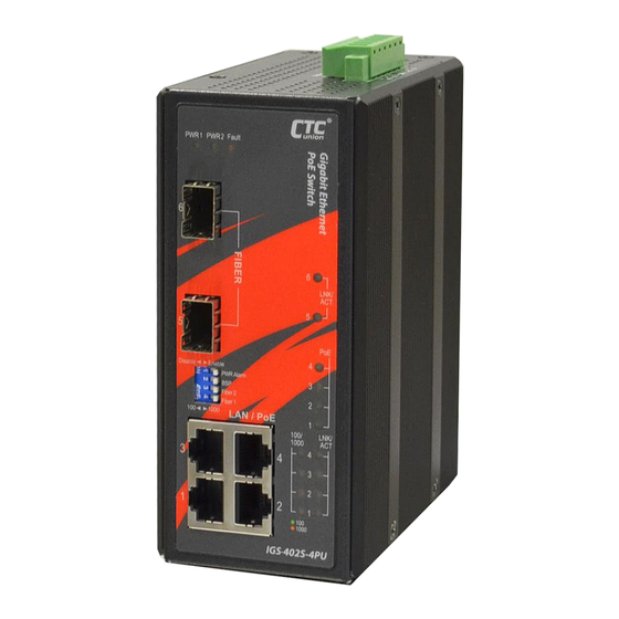
Page 8: Panels
Panels Figure 1. Front Panel Figure 2. Top Panel Description UTP RJ-45 ports (support 30W & 60W PoE function) Fiber optic SFP slots DIP switch Power & Fault LED indicators Speed & Link/ACT LED indicators for UTP RJ-45 ports PoE LED indicators Link/ACT LED indicators for fiber optic ports Power and alarm relay terminal block Earth grounding connection... -
Page 9: Lan And Fiber Ports
LAN and Fiber Ports IGS-402S-4PU(E) models have 4 LAN ports (labeled 1~4) and 2 fiber ports (SFP based, labeled Fiber 5~6) on the front panel. The LAN ports that utilize shielded RJ-45 connectors support 10/100/1000M; while the fiber SFP ports support 100/1000M. -
Page 10: Dip Switch
DIP Switch IGS-402S-4PU(E) uses a 4-pole DIP switch (as shown below) for configuration. Each pole of the switch has the following functions: DIP No. Function Status Description Provide alarm relay and fault LED Enable * indication if there is a power failure in one supply. -
Page 11: Recommended Power, Alarm, Ground Wiring Scheme
Recommended Power, Alarm, Ground Wiring Scheme DC Power Connection A removable terminal block on the top panel provides both power and alarm connections. Power can be provided through the dual inputs from separate sources (PWR1 & PWR2). One power supply is enough to power up the device. -
Page 12: Alarm Relay Connection
Alarm Relay Connection The alarm relay contact can be wired into an alarm circuit which senses an alarm condition when the contact is broken. The alarm relay is normally closed when there is no alarm condition. The alarm conditions are user programmable through management to include power, link faults or other fault conditions. -
Page 13: Led Indicators
LED Indicators Color Status Definition Power is connected and active at the PWR1/PWR2 input terminal PWR1 Green PWR2 connection. PWR1/PWR2 is not connected. One of the power inputs has fault condition. Fault Amber Normal operation without power faults or Alarm DIP switch is disabled. Lit when the LAN connected speed is Green 100M. -
Page 14: Installation
Installation The switch can be mounted on the wall or installed in DIN rail depending on your installation needs. When installing the wall-mounting bracket (optional accessory) and DIN rail bracket, be sure to correctly align the orientation pin. Figure 10. DIN Rail Figure 11. - Page 15 Version Date Description 2020/3/31 Use new document format Revise spec. CLI & WEB Info revision...
Need help?
Do you have a question about the IGS-402S-4PU and is the answer not in the manual?
Questions and answers