Table of Contents
Advertisement
Quick Links
Advertisement
Table of Contents

Related Manuals for CTC Union TP-G802TM-8PH24


Summary of Contents for CTC Union TP-G802TM-8PH24
- Page 1 Quick Installation Guide ITP-G802TM-8PH(E)24 EN50155 IP67 Managed 10 x 100/1000Base-T with 8 PoE+ Ethernet Switch ITP-G802SM-8PH(E)24 EN50155 IP67 Managed 8 x 100/1000Base-T + 2 x 100/1000Base-T SFP with 8 PoE+ Ethernet Switch sales@ctcu.com...
- Page 2 8F, No. 60 Zhouzi St., Neihu, Taipei 114, Taiwan T +886-2-26591021 F +886-2-26590237 E sales@ctcu.com H www.ctcu.com 2022 CTC Union Technologies Co., LTD. All trademarks are the property of their respective owners. Technical information in this document is subject to change without notice.
-
Page 3: Table Of Contents
Table of Contents Introduction .................. 4 Package List ................. 4 Features ..................4 Access to Command Line Interface (CLI) ........5 ..................5 ONSOLE ONNECTION /SSH C ................... 6 ELNET ONNECTION Access to Web-Based Management Interface ......7 Specifications ................8 ....................... -
Page 4: Introduction
Introduction ITP-G802TM-8PH(E)24 & ITP-G802SM-8PH(E)24 Series managed Industrial Grade Ethernet PoE+ switches that provide 10 x 100/1000Base-T Gigabit UTP with 8 PoE ports and 8 x 100/1000Base-T Gigabit UTP + 2 x 100/1000Base-T SFP with 8 PoE ports respectively. ITP- G802TM-8PH24 & ITP-G802SM-8PH24 switches equipped with PoE (Power over Ethernet) function utilize M12 connectors to ensure tight and robust connections as well as to guarantee reliable operation against environmental disturbances such as vibration and shock. -
Page 5: Access To Command Line Interface (Cli)
Access to Command Line Interface (CLI) ITP-G802TM-8PH(E)24 & ITP-G802SM-8PH(E)24 are managed Ethernet PoE switches for industrial uses. Initial configurations can be accomplished via the M12 CONSOLE port and a PC or laptop running terminal emulation software or via the M12 Ethernet port running Telnet or SSH. -
Page 6: Telnet/Ssh Connection
Telnet/SSH Connection To use Command Line Interface (CLI), you can also choose to access the device through a Telnet/SSH connection via TCP/IP network over Ethernet ports. For initial operation, use the default TCP/IP settings (10.1.1.1) to login to the device. Default TCP/IP settings: IP Address: 10.1.1.1 Subnet Mask: 255.255.255.0... -
Page 7: Access To Web-Based Management Interface
Access to Web-Based Management Interface To enter the web-based management interface for the first time or after returning the device back to factory defaults, input the default IP address “10.1.1.1” in your web browser. Then, a standard login prompt will appear depending on the type of browser used. The example below is with Firefox browser. -
Page 8: Specifications
Specifications Interface ITP-G802TM-8PH(E)24: 10 x 10/100/1000Base-T UTP(M12, 8-Pin, A- Code Female) with 8 x PoE+ ITP-G802TM-8PH(E)24-X: 10 x 10/100/1000Base-T UTP(M12, 8-Pin, X- Code Female) with 8 x PoE+ ITP-G802SM-8PH(E)24: 8 x 10/100/1000Base-T (M12, 8-Pin, A-Code Female) + 2 x 100/1000Base-T SFP slots with 8 x PoE+ ... -
Page 9: Power
Power Connector Type: 1 x M23 (5-Pin) Male Power Supply: Redundant Dual DC 24/48V (20~57VDC) input power Support Power Input Reverse Polarity Protection Support Overload Current Protection Consumption: Input Total Power Device Power Boost Series Voltage Consumption Consumption... -
Page 10: Certifications
Certifications EMC: CE EMI (Electromagnetic Interference): FCC Part 15 Subpart B Class A, CE EN55022 Class A Railway Traffic: EN50155, EN50121-4 Immunity for Heavy Industrial Environment: EN61000-6-2 Emission for Heavy Industrial Environment: EN61000-6-4 EMS (Electromagnetic Susceptibility) Protection Level: ... -
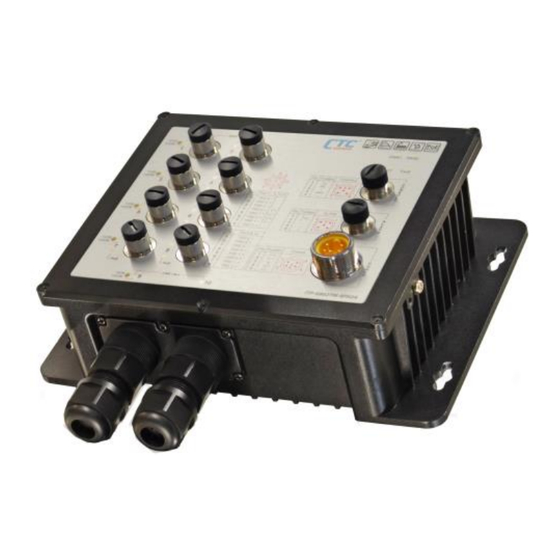
Page 11: Panels
Panels Figure 1. Front Panel of ITP-G802TM-8PH(E)24 Index Description M12 Gigabit Ethernet port 1~8 -- A-Code Model: ITP-G802TM-8PH(E)24 -- X-Code Model: ITP-G802TM-8PH(E)24-X M12 Gigabit Ethernet port 9~10 -- A-Code Model: ITP-G802TM-8PH(E)24 -- X-Code Model: ITP-G802TM-8PH(E)24-X M12 Console port M12 Alarm port M23 Power input port Link/ACT &... - Page 12 Figure 3. Front Panel of ITP-G802SM-8PH(E)24 Index Description M12 Gigabit Ethernet port 1~8 -- A-Code Model: ITP-G802SM-8PH(E)24 -- X-Code Model: ITP-G802SM-8PH(E)24-X Gigabit Ethernet SFP slot 9~10 M12 Console port M12 Alarm port M23 Power input port Link/ACT & PoE LEDs for M12 Gigabit Ethernet port 1~8 Link/ACT LEDs for Gigabit Ethernet SFP slot 9~10 Power, Fault, ACT, Ring LEDs...
-
Page 13: Pin Assignment
PIN Assignment M12 Gigabit Ethernet Port (A-Code) Port 1~8 Gigabit Ethernet RJ-45 M12 Pin No. Pinout Pinout Pin No. TDR2- TDR3+ TDR3- TDR0- TDR1+ TDR0+ TDR1- TDR2+ Table 1. Gigabit Ethernet Cable Pin Assignment (A-Code) M12 Gigabit Ethernet Port (X-Code) Port 1~8 Gigabit Ethernet RJ-45 Pinout... -
Page 14: M12 Console Port
M12 Console Port DB-9 (Female) Pinout M12 Pinout Table 3. Console Cable Pin Assignment M12 Alarm Port Color of M12 Pin No. Description Open Cable Black Normal (Relay Closed) Blue Fault (Relay Open) Orange Yellow Table 4. Alarm Cable Pin Assignment... -
Page 15: M23 Power Input Port
M23 Power Input Port M23 Pin No. Pinout Description Color of Open Cable Black 24/48VDC Blue C-GND Green Brown 24/48VDC White Table 5. Power Cable Pin Assignment... -
Page 16: M12 Cable Connector Installation
M12 Cable Connector Installation Before assembling M12 open cable, make sure you have the following M12 cable connector components (Model: M12D-M4 M12 D-Code Male) and open cable at hand. Male Contact Housing Screw Nut O-Ring Connector Assembly Steps: Step 1. Insert the screw nut, O-ring, and housing into the cable in the order shown in the figure below and keep them loose in this step. - Page 17 Step 3. Tighten the connector in clockwise direction, making sure that the wires inside the connector are not twisted as the screwed housing is assembled. Figure 7. Tighten the Connector...
-
Page 18: Fiber Cable Gland Installation For Itp-G802Sm-8Ph24 Series
Fiber Cable Gland Installation for ITP-G802SM- 8PH24 Series ITP-G802SM-8PH(E)24 Series offer two metal fiber cable glands on the bottom panel that provide watertight seals for the cable embedded inside so that fiber transmission loss due to external factors can be reduced to minimum. - Page 19 Step 5. Attach the body of the gland to the device and tighten by turning clockwise. Figure 12. Install the Body Component Step 6. Attach the split seals to the cable. Figure 13. Install the Split Seals Step 7. Slide the split seals along the cable and into the body. Press firmly to ensure the split seals are completely seated on the body.
-
Page 20: Earth Grounding Connection
Earth Grounding Connection An earth ground hole is provided on side panel. Grounding the device can help to release leakage of electricity to the earth safely so as to reduce injuries from electromagnetic interference (EMI). Prior to connecting to the power, it is important to connect the ground wire to the earth. -
Page 21: Bypass Relay Function
Bypass Relay Function ITP-G802TM-8PH(E)24 provides two copper interfaces (Port 9 & 10) with auto bypass relay function in the event of sudden power loss particularly in daisy chain or linear topology. When power failure occurs in one of the switches, bypass relay function can activate bypassing mechanism by interconnecting internal circuits automatically to ensure that links between switches operate uninterruptedly and continuously. -
Page 22: Led Indicators
LED Indicators Color Status Description PWR1 Lit if power 1 or power 2 is Green PWR2 connected and active. Lit when one or more of the Fault Amber programmable alarm conditions is active. During normal use, this LED will be lit, indicating a healthy Green condition of the running CPU. -
Page 23: Wall-Mounting & Din Rail Installation
Wall-Mounting & DIN Rail Installation The ITP-G802TM-8PH(E)24 and ITP-G802SM-8PH(E)24 Series come with both wall mount (standard accessory) and DIN rail hardware brackets (optional accessory). The wall mount bracket has been attached to the device. Therefore, there is no need to install wall mount bracket. Wall mounting Wall mounting holes... -
Page 24: Application
Application Figure 23. Onboard Train Application for ITP Series... - Page 25 Version Date Description 2022/8/2 Use new format.
Need help?
Do you have a question about the TP-G802TM-8PH24 and is the answer not in the manual?
Questions and answers