Table of Contents
Advertisement
Quick Links
Advertisement
Table of Contents

Related Manuals for LifeGear TRANSPORT ML


Summary of Contents for LifeGear TRANSPORT ML
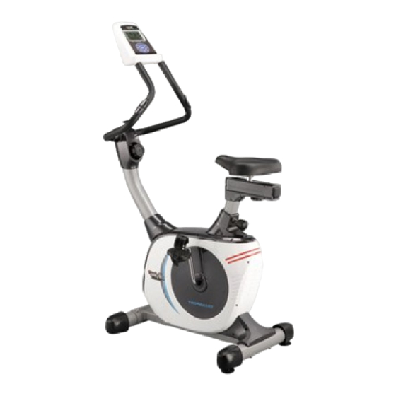
- Page 1 TRANSPORT ML MAGNETIC UPRIGHT BIKE ITEM NO.: 20680 OWNER’S MANUAL IMPORTANT: Read all instructions carefully before using this product. Retain this owner’s manual for future reference. The specifications of this product may vary from this photo, subject to change without notice.
-
Page 2: Table Of Contents
TABLE OF CONTENTS WARRANTY ------------------------------------------------------------------------------- 2 IMPORTANT SAFETY INSTRUCTIONS ------------------------------------------- 3 PARTS LIST ------------------------------------------------------------------------------- 4 HARDWARE PACKING LIST --------------------------------------------------------- 6 TOOLS -------------------------------------------------------------------------------------- 6 OVERVIEW DRAWING ----------------------------------------------------------------- 7 ASSEMBLY INSTRUCTIONS --------------------------------------------------------- 8 OPERATING THE COMPUTER ------------------------------------------------------ 12 ADJUSTMENTS -------------------------------------------------------------------------- 14 MAINTENANCE -------------------------------------------------------------------------- 15 TROUBLESHOOTING ------------------------------------------------------------------ 15 WARM UP AND COOL DOWN ROUTINE ----------------------------------------- 16... -
Page 3: Warranty
ONE YEAR LIMITED WARRANTY LifeGear Inc. warrants to the original purchaser that this product is free from defects in material and workmanship when used for the purpose intended, under the conditions that it has been installed and operated in accordance with LifeGear's Owner's Manual. LifeGear's obligation under this warranty is limited to replacing or repairing free of charge, any parts which may prove to be defective under normal home use. -
Page 4: Important Safety Instructions
IMPORTANT SAFETY INSTRUCTIONS Basic precautions should always be followed, including the following important safety instructions when using this equipment. Read all instructions before using this equipment. Read all instructions and follow it carefully before using this equipment. Make sure the equipment is properly assembled and tightened before use. -
Page 5: Parts List
PARTS LIST Description Qty No. Description 001 Computer (XLG-903) 1 028 Seat Sliding Tube Bolt 002 Seat Sliding Tube 38x38x1.5 1 029 Big Washer Ø8xØ20x2 003 Screw ST2.9x16mm 13 030 Seat Adjustment Knob M8 004 Handlebar Ø28x1.5 1 031 Seat Post 005 Handlebar Foam Grip 2 032 Seat Post Cover Ø27xØ33x730... - Page 6 PARTS LIST Description Qty No. Description 055 Pan Head Phillips Self Drilling 4 067 Bearing Nut I 15/16" Screw ST4.2x25 056 Nut M6 2 068 Washer Ø40xØ24x3 057 Spring Washer Ø6 2 069 Screw ST4.2x25 058 Tension Bracket 2 070 Right Shroud 059 Nut M10x1x10 2 071 Spring Ø17x80xØ2.5 060 Eyebolt M6x36...
-
Page 7: Hardware Packing List
HARDWARE PACKING LIST (3) Screw ST2.9x16mm (7) Screw ST4.2x20mm (44) Carriage Bolt M8x90mm 13 PCS 5 PCS 2 PCS (45) Big Curve Washer (46) Cap Nut M8 (77) Bolt M8x90mm Ø8xØ20x2 2 PCS 2 PCS 4 PCS TOOLS Allen Wrench S6 Multi Hex Tool with Phillips Screwdriver 1 PC S10, S13, S14, S15... -
Page 8: Overview Drawing
OVERVIEW DRAWING... -
Page 9: Assembly Instructions
ASSEMBLY INSTRUCTIONS Tool: Multi Hex Tool with Phillips Screwdriver S10, S13, S14, S15 Allen Wrench S6 1. Front/Rear Stabilizers and Right/Left Foot Pedals Installation Position the Front Stabilizer (43) in front of Main Frame (48) and align bolt holes. Attach the Front Stabilizer (43) onto the front curve of the Main Frame (48) with two M8x90mm Carriage Bolts (44), two Ø8xØ20x2 Big Curve Washers (45), and two M8 Cap Nuts (46). - Page 10 Hardware: (44) Carriage Bolt (45) Big Curve Washer (46) Cap Nut M8 (77) Bolt M8x90mm M8x90mm Ø8xØ20x2 2 PCS 2 PCS 2 PCS 4 PCS ․․․․․․․․․․․․․․․․․․․․․․․․․․․․․․․․․․․․․․․․ Tool: Multi Hex Tool with Phillips Screwdriver S10, S13, S14, S15 Multi Hex Tool S10, S13, S17, S19 2.
- Page 11 Hardware: (3) Screw ST2.9x16mm (7) Screw ST4.2x20mm 5 PCS 2 PCS ․․․․․․․․․․․․․․․․․․․․․․․․․․․․․․․․․․․․․․․․ Tool: Allen Wrench S6 3. Handlebar Post and Handlebar Post Cover Installation Remove six M8x15 Bolts (19) and six Ø8xØ16x1.5 Curve Washers (20) from the Main Frame (48). Remove bolts and curve washers with the S6 Allen Wrench provided. Slide the Handlebar Post Cover (21) up to the Handlebar Post (14).
- Page 12 Tool: Multi Hex Tool with Phillips Screwdriver S10, S13, S14, S15 4. Handlebar, Front/Rear Decorative Covers for Handlebar Post, and Computer Installation Place the Handlebar (4) through clamp on the top end of the Handlebar Post (14). Connect the Extension Sensor Wire (13) from the Handlebar Post (14) to the Extension Sensor Wire (13) from the Handlebar (4).
-
Page 13: Operating The Computer
OPERATING THE COMPUTER SPECIFICATIONS: TIME --------------------------------------------------- 0:00-99:59 MIN: SEC SPEED ------------------------------------------------ 0.0-99.9 KM/H DIS. (DISTANCE) ----------------------------------- 0.00-99.9 KM CAL. (CALORIES) ---------------------------------- 0.0-999 KCAL PULSE ------------------------------------------------ 40-200 BEATS/MIN USING YOUR COMPUTER The computer can be activated by pressing the buttons or by pedaling. If you leave the equipment idle for approximately 4 minutes, the power will turn off automatically. - Page 14 press the SET button TIME should change by 1 minute. Press the RESET button to clear the target time to zero. The pre-set target time range is from 00:00 to 99:00 minutes. Once you pre-set target time and then start to exercise, time starts counting down from pre-set target time to 0:00 per 1 second backward.
-
Page 15: Adjustments
ADJUSTMENTS Adjusting the Adjustable Leveler Turn the adjustable leveler on the rear stabilizer as needed to level the upright bike. Adjustable Leveler Adjusting the Seat Forward or Back Turn the seat adjustment knob to loosen the seat sliding tube. Slide the seat sliding tube forward or back to desired position and turn seat adjustment knob to tighten. -
Page 16: Maintenance
MAINTENANCE Cleaning The upright bike can be cleaned with a soft clean damp cloth. Do not use abrasives or solvents on plastic parts. Please wipe your perspiration off the upright bike after each use. Be careful not to get excessive moisture on the computer display panel as this might cause an electrical hazard or electronics to fail. -
Page 17: Warm Up And Cool Down Routine
WARM UP AND COOL DOWN ROUTINE The WARM-UP is an important part of any workout. The purpose of warming up is to prepare your body for exercise and to minimize injuries. Warm up for two to five minutes before aerobic exercising. It should begin every session to prepare your body for more strenuous exercise by heating up and stretching your muscles, increasing your circulation and pulse rate, and delivering more oxygen to your muscles. - Page 18 QUADRICEPS STRETCH With one hand against a wall for balance, reach behind you and pull your right foot up. Bring your heel as close to your buttocks as possible. Hold for 15 counts and repeat with left foot. INNER THIGH STRETCH Sit with the soles of your feet together and your knees pointing outward.
Need help?
Do you have a question about the TRANSPORT ML and is the answer not in the manual?
Questions and answers